Soundfield MKV User manual

The Soundfield MKV
Microphone
User Guide
527 - 027

SoundField MKV Issue 1.1 User Guide
Contents
Introduction 3
Optional accessories 3
Power requirements 3
Getting started 4
Application Suggestions 5
TheControls-inmoredetail 6
Checks andAlignments 10
Warranty 14
AppendixA-TheoryofOperation 17
AppendixB-CableandConnectorDetails 19
2

3
SoundField MKV Microphone Issue 1.1 User Guide
Introduction
The SoundField MKV Microphone System is a unique product offering a previously unobtainable
degree of accuracy in the generation of coincident stereo and mono microphone patterns. The user
is able to steer and move the generated microphones both in real and post-production time. A fully
three dimensional output signal suitable for encoding to any surround system and, in particular, to
the UHJ family of Ambisonic Surround Sound systems is available.
Thesystemcomprises:
•The MKV Soundfield Microphone in presentation box
•TheMKVSoundfieldControlUnit
•Shock Mount Assembly
•20metremicrophonecable
•Mains lead
•Foamwindshield
OptionalAccessories
•100metremicrophone lead/extensioncableondrum(NN2886),5m cable(NN2882),
10m cable(NN2883),20mcable(NN2884)and50mcable(NN2885).
•Twosplitter cables typeNN2877 and NN2878 allowthe microphone tocontrol
unit connection to be made via 5 separate studio 3 pin XLR tie lines thus placing
the control unit in the listening room (both cables are required).
•RycoteKitcomprisingof:
1x Rycote suspension with pistolgrip(430-385)
1xRycote140mmWindshield(430-384)
1xRycoteMountingKit (440-182)
•RycoteWindjammer(430-398)
(tofitRycoteWindshield430-384)
PowerRequirements
TheSoundField MKVControlUnit may beoperatedfrom200/250 or100/120voltsAC Mains.
The Control Unit incorporates a mains filter and must therefore have mains earth connected.
Getting Started
Plugging-up
• Control unit with the microphone in the studio: connect the microphone to the control
unit using the multi-way cable.
• Control unit in the control room and the microphone in the studio: use the 5 x 3 pin
female XLR 's to Tuchel Male Plug splitter lead (NN2877) to connect the control unit in
the control room to the microphone lines to the studio. Use the 5 x 3 pin male XLR's to
l Tuchel Female Socket lead (NN2878) to connect the microphone to the studio
microphone lines which lead to the control unit in the control room.
DONOT CONNECTOR DISCONNECT THEMICROPHONE TO
THECONTROLUNITWHEN THEUNIT ISPOWERED.
TAKE CARETOPLUG THECORRESPONDING3 PINXLR's TO
THE SAME MICROPHONE LINE OR DAMAGE COULD
RESULT. THE STUDIOTIE LINESSHOULDNOT HAVE
PHANTOM POWER ON THEM.
PositioningtheMicrophone
The front of the microphone is marked by the SoundField logo.
SettingaStereoMicrophoneOutput
The left and right XLR-3 outputs from the control box are at line leveland need to be plugged into
the line inputs of your recorder or desk and not into your mic inputs. Plug in and switch on the
SoundFieldControlUnit.
Ensure that the SoundField solos and osctest are off (red LEDs flash if they or the oscillator are
on).
Ensure that the dub, tape and SoundField buttons are out.
Put the fine gain at the detente and adjust the microphone gain to give just enough level to
modulate the bargraph meters around ‘0’.
The stereo outputs are now providing an output of a stereo or mono microphone with a polar
response pattern set by the left knob under the stereo microphone section and at a capsule angle
set by the right hand knob. For a crossed pair, set the pattern to cardioid (at 12 o’clock) and select
90° on the capsule angle.
Now listen to your stereo SoundField Microphone.
SoundField MKV Issue 1.1 User Guide
4

SoundField MKV Issue 1.1 User Guide
5
Movingthe MicrophoneRemotely
Set all the SoundField controls to ‘0’.
Switch the SoundField controls into circuit with the SF in button.
Pan the microphone left or right with theazimuth knob. You will find that the sound moves left as
you pan right.
Tilt the microphone 45° up or down with the elevation knob.
Zoom the microphone in closer to the sound with the dominance knob. You can effectively halve
the distance between the microphone and the sound source with this control. You can zoom in on a
vocalist without vocal pops, or adjust the balance between the sound of plucked strings and the
instrument itself using this dominance control.
It should, however, be noticed that the dominance control will not produce any effects that could
not be produced by adjusting the pattern, angle and gain controls.
Zoom the microphone out further and listen to the studio acoustics, and let the myriad of
reflectionsmingle with the directsignal.
Application Suggestions
LeadVocals
Selecta mono (0° angle) or stereo (90° or wider) cardioid, forward facing (azimuth 0°), start withhalf
forward dominance and if you have time, tune this for best effect. Why not use the microphone in
the control room? The accurate polar pattern will allow the dead sides to be faced to the monitors -
try reversing the phase of the microphone or the vocal track.
BackingVocals
As above but usually stereo sub-cardioid and the dominance at ' 0 ' or slightly anti-clockwise for
more ambience. If the microphone is positioned above the backing vocalist, then correct its
placement with the elevation control.
Drum Microphone
Select mono cardioid. Because the pattern is accurate at all audio frequencies, there will be no spill
from other drums. If you want the microphone away from the drum skin and out of harm, use full
frontal dominance. No matter how loud the bass drum is, it won’t distort this microphone.
Piano
Use as any stereo microphone but tune the sound using all the controls to get it just right - at least
you don’t need to keep running into the studio to do this! Remember you cannot reduce reflections
from the lid meeting the microphone front side on, even with a SoundField.
Ambience
Again use as any stereo microphone, select figure-of-eight pattern at 90° or crossed cardioids, and
if the microphone is high use the elevation control to bring the sound on axis. If the microphone is
positioned upside down then press the invert button and left and right will be switched over.

6
SoundField MKV Issue 1.1 User Guide
The Controls - in more detail
1 Input Gain - controls the sensitivity of the microphone over a 30dB range in 10dB steps.
2 Fine Gain- should normally be operated as near to the zero mark as possible but allows a
+10dB to - 10dB fine trim. It is accurately calibrated at the detente and the two ends.
3 Solos - (LB - LF+ RF- RB+) Soloing a capsule means that only that par ticular capsule is
being heard. If two buttons are pressed then both are heard.
Undernocircumstancesshouldrecordingtakeplacewithanysolobutton
depressed.
The main use of the solos is for checking continuity when the head lead has been
split-out into existing tie lines using the SFS 1 and SFS 2 splitter leads. It is good
SoundField practice, though, to check before every recording, as head leads do get
damaged, and, while under normal circumstances it would be obvious from the
monitored output that all was not well, under difficult monitoring conditions on
headphones a discontinuity could go un-noticed.
4Osc.test -the test oscillator produces a 0dBm/1kHz tone at the B-Format record
outputs which should be used to align the multi-track tape machine record circuits.
The tone is coded for later identification of the recorded tracks and the following
track plan is recommended as a standard for professional use:
Tapetrack B-Formatsignal Oscillatorcodingapprox.seconds
ON OFF
1 W Continuous --
2 X 1 1
3 Y 2 2
4 Z 4 4
The Y tone sequence is twice as long as the X sequence and the Z is twice as long as
the Y.
It is imperative that test tones be recorded at the beginning of each
session and preferably on each reel of tape.
If a noise reduction system is used, the SoundField test tones should be after those of the noise
reduction system. The recorded tones may then be used to align the tape replay section and
to check for correct connections of tracks.
The absolute level of the replayed test tone is not important but it is vital to adjust each track to
the same relative level.
SoundField MKV Issue 1.1 User Guide
7
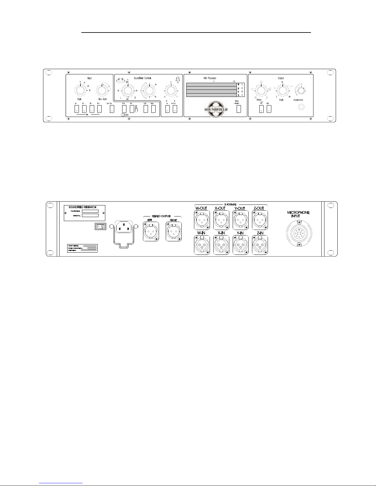
Front Panel
Rear Panel

SoundField MKV Issue 1.1 User Guide
7 Tape and Dub - The normal condition is the B-Format output of the microphone input stage to
be routed direct to the stereo output via the SoundField controls if selected. Tape substitutes the
microphone signal with the off tape input to the B-Format replay socket and would normally be
used for ‘tape check’ during recording. Dub disconnects the microphone completely and routes the
B-Format replay input to the fine gain and also to the B-Format record output and the stereo
output. This action reverses the roles of the B-Format inputs and outputs and should never be used
duringrecording. Thefacilityallows B-Format toB-Formatand/or B-Formattostereodubbing with
fine gain control and SoundField control if required. The polar pattern and capsule angle controls
are always available in the stereo output.
8 Azimuth - complete electronic rotation of the microphone.
9 Elevation- allows plus or minus 45° of continuous variation on the vertical alignment of the
actualmicrophone.
8
5Red LEDs- flash with each solo button and when the oscillator is in operation.
6 Microphone Orientation
End Out Inv Out
End Out Inv In
End In Inv Out
End In Inv In
Right
Left
SOURCE
Right
Left
SOURCE
Right
Left
SOURCE
Right
EndFireMic
Inverted
EndFireMic
Inverted
Side Fire Mic
Side Fire Mic
Left
SOURCE

SoundField MKV Issue 1.1 User Guide
9
10 Dominance - in effect, this is a form of zoom control allowing the generated microphone to be
moved closer to or further away from the original sound source than the actual microphone. The
effect in stereo is not exactly the same as moving the microphone because the stereo image does
not widen as would be expected, in fact it narrows slightly, but this effect can be corrected with the
‘Capsule angle’ control. In surround sound the apparent movement is even more realistic.
11 SoundField In Button - routes the B-Format signal through the SoundField control section. If
no SoundField correction is to be made the section should be switched out of circuit to avoid
accidental adjustment.
12 SoundField Rec Button - In normal or dub operation the SoundField controls are inserted into
the B-Format signal after the B-Format record outputs and only affect the stereo output.Rec allows
their insertion into the B-Format record outputs, enabling corrections to be made onto 4 track tape
as well as the stereo output.
13 Metering- the 4 bargraph LED meters show the signal levels of the 4 components of the B-
Format signal W, X, Y and Z as they appear either at the B-Format output or off tape at the B-
Format input. In either case they show the effect on signal level of any SoundField adjustments and
directlyrepresentthesignal level attheB-Format outputs.Whenused directly asastereo
microphone or on subsequent mixdown of a B-Format signal to stereo they only show the energy
being fed to the stereo output circuits and do not show the energy level of the stereo output.
The bar-graphs are calibrated to illuminate 13 green segments at 0dBu line-up tone, and the panel is
marked at this position. The calibration is such that the alignment tone only just illuminates
segment 13 so that if a tape machine is being aligned prior to recording, the recorder replay gain
should be set so that segment 13 just turns on.
Segments14 - 23are red representing 0- 20dB in intervalsof -2dB.
The indicators have very approximate ‘Peak programme meter’ attack and decay times and are not
intended as a serious replacement for superior programme metering.
14 Stereo Microphone controls - the polar pattern control is graduated from omni-directional (0) at
the anti-clockwise end through cardioid at ‘12 o’clock’ to figure-of-eight at the clockwise end and
smoothly adjusts the polar pattern of the generated microphone(s) through all the intermediate sub-
cardioid and hyper-cardioid positions. The capsule angle control is graduated from 0° to 180° and
smoothly adjusts the angle of the generated microphones between the two extremes. With the
control set to 0° the two outputs would be of two microphones pointing in exactly the same
direction from exactly the same point in space and would therefore be identical mono signals.
5Monitor.- controls the signal level of the stereo output to the headphone socket.
16 High pass filter - on the stereo outputs at 40Hz, 18dB per octave. Used to remove ‘rumble’ and
wind noise. Affects the stereo and M/S outputs only.
17 M/S - switches the microphone into M and S mode outputs. The Left socket becomes M and
the Right socket becomes S.

SoundField MKV Issue 1.1 User Guide
10
Checks and Alignments
The SoundField System produces near perfect figure-of-eight patterns making it possible to
substantially check the microphone using speech tests only, preferably using headphones.
Set the microphone on a stand or boom at a comfortable height to walk around but low enough to
get your head over the top. Set the controls as follows:
.
1 Solos normal(off)
2 Osc off
3 Invert/End to suit microphone position
4 Gain to give comfortable listening level
5 Azimuth 0
6 Elevation 0
7 Dominance 0
8 In de-selected
9 Rec de-selected
10 Tape de-selected
11 Stereo pattern figure-of-eight
12 Stereo angle 0°
First solo each capsule and listen to one at a time to check the continuity of the microphone lead.
If a speech check is conducted at this point it should be possible to ascertain the direction of each
individual capsule in the horizontal and, if the test room is not too reverberant, the vertical.
LB - = left back down
LF+ = left front up
RF - = right front down
RB+ = right back up
Left and right are defined as being the left and right hand side of the stereo picture ie they will be
reversed if you face the front of the microphone.
This test is optional provided that a roughly equal signal is received from each capsule. (Bearing in
mind that two face forwards and two face backwards and that two face upwards and two face
downwards).
De-select all the solo buttons and select the SoundField in button.
The unit is now set to produce a forwards facing mono figure-of-eight.

11
SoundField MKV Issue 1.1 User Guide
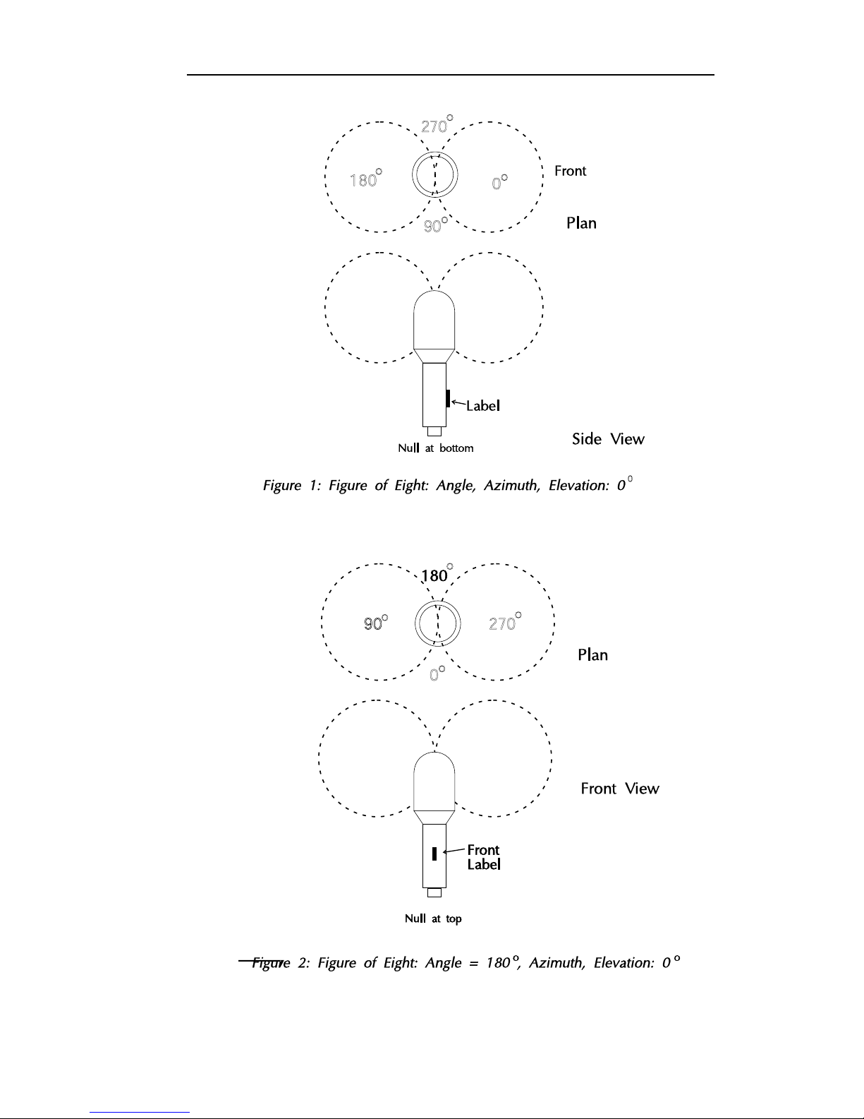
Test 1 To speech check, start at the front of the microphone at about 150mm (6 inches)
range and progress clockwise around horizontally, noting the signal peaks at 0° and
180° and the nulls at 90° and 270°.
Similar nulls should also be found immediately over the top and underneath
the microphone (see Figure 1 - Page 12)
Test 2 Aim the microphone 90° to the right by rotating the azimuth control 90° clockwise - (see
Figure 2 - Page 12 )The signal peaks and null will have moved round 90° relative to the
label.
Test 3 Repeat the test with 90° rotation anti-clockwise and results should be as Test 2.
Test 4 Repeat the test with 180° rotation and results should be as Test 1.
Test 5 Return the controls to forward facing, as in Test 1 and select 45° clockwise on the azimuth
control. The peaks and nulls will now have moved 45° to the right of microphone front (ie
halfway between Figures 1 and 2).
Test 6 Repeat Test 5 with the azimuth control selected to 45° anticlockwise. The peaks and nulls
will now be 45° to the left of microphone front. (Again, halfway between figures 1 and 2 but
at 90° to Test 5).
Test 7 Return the azimuth to 0° and turn elevation to +45°. The peaks should now be at +45°
relative to microphone front and -45° relative to microphone back as in Figure 3.
Test 8 Repeat Test 7 at -45° and note that the peaks move to this position relative to
microphone front and 45° relative to microphone back as in Figure 4.
Test 9 Return the elevation control to 0° and whilst speaking at the microphone front, note
that increasing dominance increases the microphone sensitivity and reducing
dominance reduces the sensitivity.
Test 10 Return the dominance control to 0° Move the polar pattern control and observe that the
microphone works as a single cardioid with a null at 180° (microphone back) in
cardioid position and all around equally in omni position.
Test 11 With the microphone set as a cardioid check that the dominance has a similar effect as
Test 10. Return the dominance control to 0° and de-select SF IN.
Test 12 Set the stereo controls to cardioid and 90° and observe that the left signal peaks when
speaking at 45° microphone left (to your right) and the right one at 45° microphone right
(to your left) with corresponding opposite nulls.
Conclusions
If all the above tests have produced the results described, then the system can be assumed to be
workingcorrectly.
12
SoundField MKV Issue 1.1 User Guide
270o
270o
180o
o
o
0o
0o
90o
90o

SoundField MKV Issue 1.1 User Guide
13
o
o
o
o
o
o
o
o
o

14
SoundField MKV Issue 1.1 User Guide
Warranty
LimitedLiability
SoundField Research Ltd., herein after known as the manufacturer, guarantees this equipment from
defects in material and workmanship under normal use and service for a period of one year. This
guarantee extends to the original purchaser only and does not apply to fuses or any product or
parts subjected to misuse, neglect, accident or abnormal conditions of operation. The guarantee
begins on the date of delivery to the actual purchaser or to his authorised agent or carrier. In the
event of failure of a product covered by this guarantee, the manufacturer or their certified represen-
tatives will repair and calibrate equipment returned prepaid to an authorised service facility within
one year of the original purchase and provided that the guarantors examination discloses to its
satisfaction that the product was defective, equipment under this guarantee will be repaired or
replaced without charge. Any fault that has been caused by misuse, neglect, accident, act of God,
war or civil insurrection; alteration or repair by unauthorised personal; operation from an incorrect
power source or abnormal conditions of operation, will not fall under this guarantee. However, an
estimate of the cost of the repair work will be submitted before work is started. The manufacturer
shall not be responsible for any loss or damage, direct or consequential, resulting from machine
failure or the inability of the product to perform. The manufacturer shall not be responsible for any
damage or loss during shipment to and from the factory or its designated service facility. This
guarantee is in lieu of all other guarantees, expressed or implied, and of any other liabilities on the
manufacturers part. The manufacturer does not authorise anyone to make any guarantee or assume
any liability not strictly in accordance with the above. The manufacturer reserves the right to make
changes or improvement in the design and construction of this unit without obligation to make
such changes or improvements in the purchaser’s unit. Any dispute arising from this warranty shall
be subject to the laws of England.
Whattodoifafaultisfound
If a fault develops in the unit, notify .SoundField Research Ltd. or their nearest service facility
giving full details of the difficulty. On receipt of this information, service or shipping instructions
will be forwarded to you. No equipment should be returned under the warranty without prior
consent from SoundField Research Ltd. or their Authorised Representative.

15
SoundField MKV Issue 1.1 User Guide
ShippingInformation
Authorised returns should be prepaid and must be insured. All SoundField products are packaged
in specially designed containers for the best possible protection. If the unit is returned the original
container should be used. If this is not possible, a new container can be obtained from SoundField
Research Ltd.; please specify the model number when requesting a new container. If the specially
designed container is not used ensure that a suitable rigid container of adequate size is used, wrap
the instrument in paper and surround it with a good thickness of shock absorbing material.
Claimfordamageduringtransit
The instrument should be thoroughly inspected immediately upon delivery to the purchaser. If the
instrument is damaged in any way a claim should be filed with the carrier immediately. A quotation
to repair shipment damage can be obtained from .SoundField Research Ltd. or their Certified
Representative. Final claims and negotiations with the carrier must be completed by the customer.
Applicationsproblems
SoundField Research Ltd. will be happy to answer all applications questions to enhance your use
of this equipment. Please address all correspondence to:
SoundFieldResearchLtd.
Charlotte Street Business Centre
CharlotteStreet
Wakefield
WestYorkshire
WF11UH
ENGLAND

16
SoundField MKV Issue 1.1 User Guide
Quality Assurance and Service Policy
Over the years SoundField products have gained an enviable reputation for their quality of design,
performance and reliability, however, in the unlikely event that problems are encountered with this
unit, please contact SoundField Service at the appropriate address below or alternatively inform
one of our world wide network of distributors who will be able to assist with any of your queries.
SoundFieldResearchLtd.
Charlotte Street Business Centre
CharlotteStreet
Wakefield
WestYorkshire
WF11UH
ENGLAND
All SoundField products are sold subject to our ‘General Conditions of Sale’ and the purchaser
should note ‘that the equipment is not being sold to him to meet his individual requirements and it
is therefore the buyer’s responsibility to ensure that the purposes and functions of the equipment
meet his requirements prior to purchase.’ However, we would non-the-less be grateful to receive
any constructive criticism or ideas for additional features which you feel might enhance the
usefulness of our product in the studio environment. At SoundField Research Ltd., we have an
‘advanced module replacement policy’ so that following telephone/fax diagnosis of your problem,
equipment can be despatched as quickly as possible to reduce the product’s ‘down time’ and
ensure complete customer satisfaction with as little fuss as possible.
All we ask is that you return the defective module within one month to assist our investigations
and help minimize the likelihood of the problem re-occuring. Any charges levied for service is
dependent on the warranty period of the product and the prompt return of modules affected.
SoundFieldResearchLtd.
Charlotte Street Business Centre
CharlotteStreet
Wakefield
WestYorkshire
WF11UH
ENGLAND

17
SoundField MKV Issue 1.1 User Guide
X
2
Y
2
Y
2
-Y
2
1
2
2
APPENDIX A Theory of Operation
SoundFieldControls
Azimuth, Elevation and Dominance are effected by adding or subtracting appropriate other B-
Format components to each basic B-Format signal either in-phase or inverted to achieve a desired
result.
For example if it is required to effectively move the front of the microphone 45° to the left then the
‘new X’ or X’, must now consist of equal components of X and Y but so that the amplitude of X’ is
identical to that of X, the X and Y constituents must each be reduced by a factor of or -3dB
(SeeFigure1-Page18).
Similarly 45° to the right requires the same component of X ie
but now the added Y component requires to be
Thus the azimuth control in the front sector merely reduces X by 3dB at each end relative to centre,
the signals remaining in-phase, whereas the added component, . (-3dB) at left, disappears at
centre and re-appears as (-3dB) at right ie inverted.
This is the key to understanding and testing all SoundField circuits.
The basic signal component is varied in amplitude from its 0dB neutral position whilst remaining in-
phase (it actually increases in the Dominance circuit) whilst the added signal component appears in
opposite phase on either hand from a zero value at neutral. The maximum value of the added signal
at the ends of the controls is always or -3dB.
Once this principle is understood, the required phase of the added signal to achieve a desired
result can easily be determined by reference to the B-Format signal vectors (See Figure 2). For
example, if the microphone requires to be tilted up, (elevation control) X’ must now contain some
+Z and Z’ some -X, or tilted down, X’ must contain some -Z and Z’ some +X and so on (See Figure
3). Each of the 3 B-Format directional signals has a ‘positive hemi-sphere’ in which its vector lies,
and an opposite ‘negative hemi-sphere’.
Dominance is slightly more complicated (but only slightly). This control breaks the basic symmetry
of the SoundField sphere and causes it to ‘bulge’ forwards or backwards. This is achieved by
adding or subtracting some X to the W component to make it into a front or back facing sub-
cardioid* and at the same time adding or subtracting W to the X component to form a front or back
facinghyper-cardioid*.
*It must be remembered that equal quantities of W (pressure, omni-directional) and X (pressure-
gradient, figure-of-eight) components form a front facing cardioid. If X is subtracted (inverted), this
is a back facing cardioid. If W is greater than X then the polar pattern is said to be a sub-cardioid; if
X is greater than W, a hyper-cardioid. There is a range of sub and hyper-cardioids but only one
cardioid. A fuller explanation of this is given in the next section.

SoundField MKV Issue 1.1 User Guide
18
Figure 1 - Azimuth Control
Components of B Format

19
SoundField MKV Issue 1.1 User Guide
StereoOutputs
There are 2 stereo outputs from the control unit:
1The main stereo output (left and right) from 2 x XLR 3 pin male sockets on the rear panel. These
signals are not subject to the monitor gain control.
2 A stereo jack socket on the front panel.
The stereo output circuits are fed with B-Format signals W, X and Y from the record amplifiers (and
hence the microphone) in the normal mode (Z, the height component, is not used in stereo except in
the SoundField circuits to effect elevation when required). If tapeis pressed the circuits are
switched to the B-Format signals from the tape recorder via the B-Format play socket. Ondub the
record level control may be introduced.
Themainstereooutputlevelsare approximately0dBuprogrammelevelfor 0dBuB-Format
programme inputs. Level adjustment is available in the dub mode. The monitor jack outputs may be
adjusted from off to +10dB relative to the main levels.
There are two further controls for when the unit is being used as a stereo microphone, or when
dubbingfromtheB-FormattoStereo,or(experimentally)whenmonitoringaB-Formatrecordingin
stereo. These are polar patterns and angle, the latter allowing adjustment of the ‘angle of point’ of
the synthesised stereo pair of microphones.
Note 1
In standard B-Format the pressure-gradient signals X, Y (Z) are enhanced 3dB.
Examples of the inter-play of these controls and general polar pattern theory may be seen in
Figure5
.
Note 2
The stereo output signals are in phase with the acoustic signals. That is, a pressure increase is
reproduced as a positive going omnidirectional component at the stereo outputs.
The B-Format signals are inverted. This has been done to retain compatibility with previous
SoundField microphones. This will only affect you if you wish to manipulate the B-Format signals
independently at the SoundField control unit.

2 0
SoundField MKV Issue 1.1 User Guide
Fig 5a Mono polar patterns
Fig 5b Two of many Stereo configurations from the Soundfield microphone
Front Cardioid
Omni and Figure of eight
Back Cardioid
Omni minus Figure of eight
Sub-Cardioid (2+cos )
Omni greater than the Figure of eight
Hyper-Cardioid (0.5+cos )
Omni less than the Figure of eight
Omni
Omni
Omni
Omni
Figure of eight
Figure of eight
Figure of eight
Figure of eight
φ
φ
Stereo pair of synthesised
cardioid microphones
Stereo pair of synthesised
hyper-cardioid microphones
set at 120oand tilted downwards.
Front
Right
Right
Left
Left
120o
Table of contents
Other Soundfield Microphone manuals


