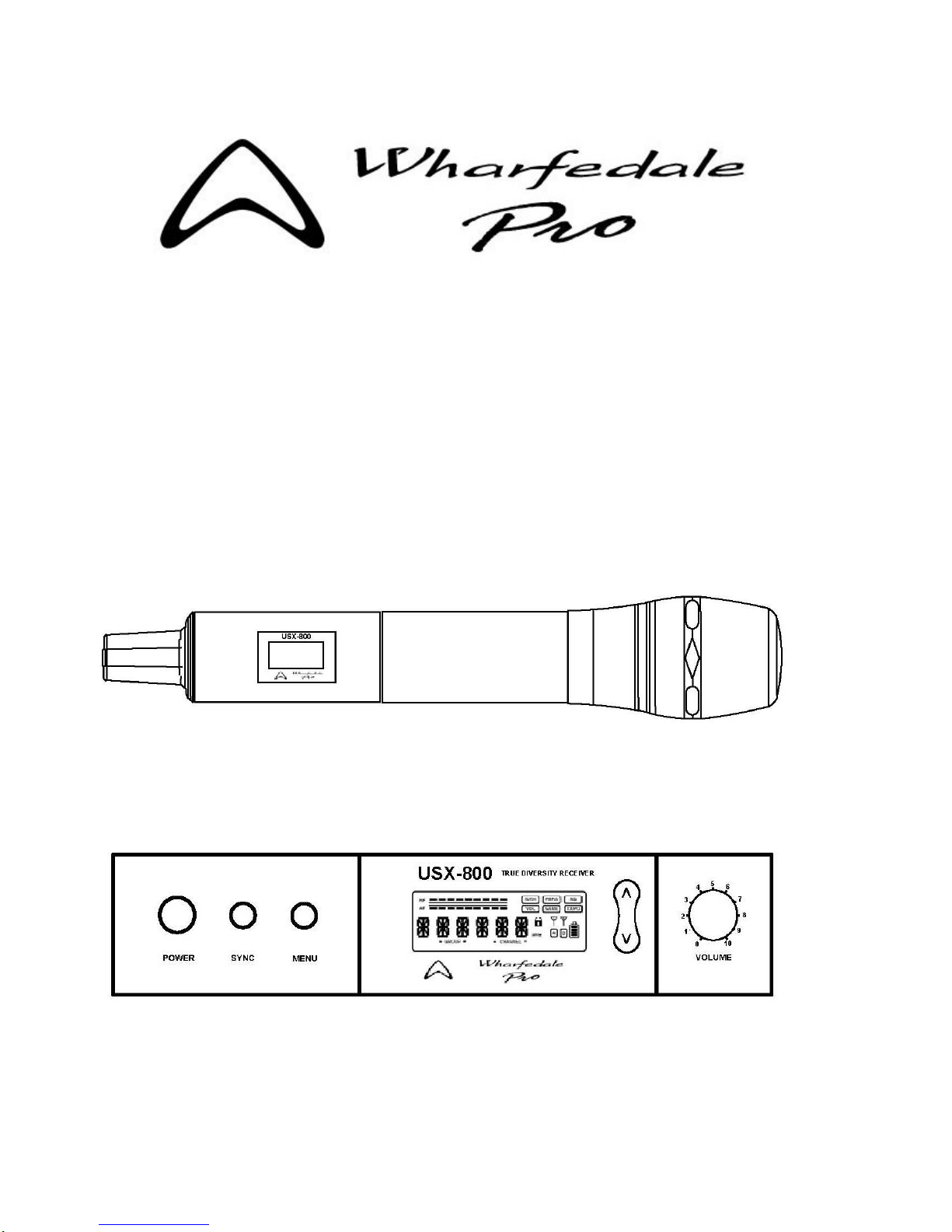
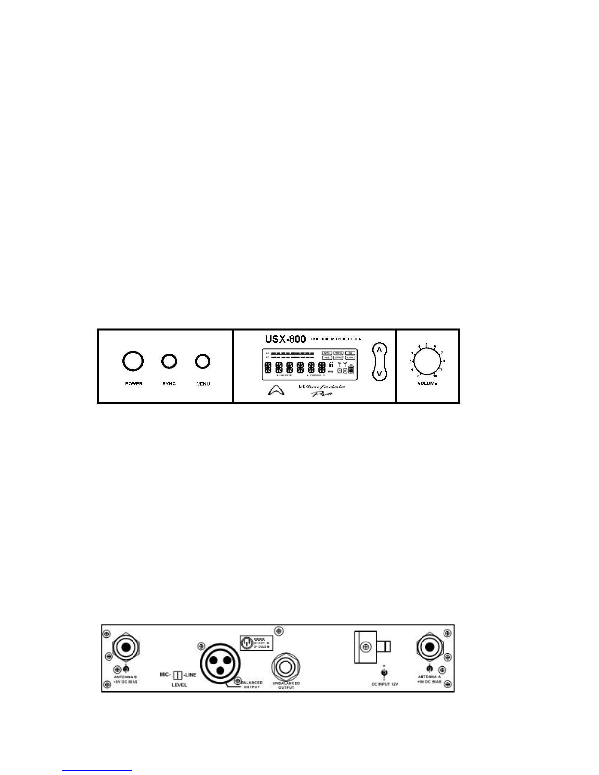
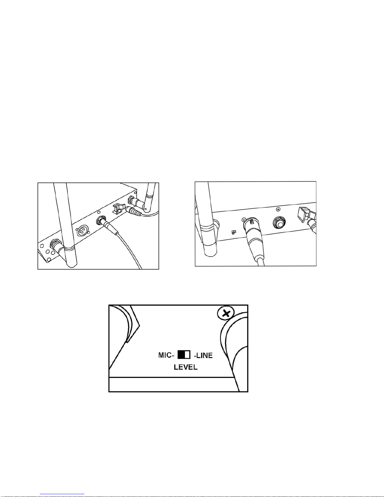
Wharfedale Pro USX 800 User manual

Wireless Microphone

Wharfedale Pro USX-800 - Single Channel Wireless Microphone System
Preliminary Wireless Microphone User Manual
Table of Contents
1…Table of Contents / Warranty Statement / Warnings & Disclaimer
2…Preface / System Inventory
3…Parts Names and Functions
4…Setup (Transmitter / Microphone)
5…Installation of the Receiver
6…Audio Output Connections
7…Receiver Settings / Lock / Unlock Function
8…LCD Display Legend / Display Modes
9…Function Descriptions / Battery Status
10..Specifications
11..Appendix
12..Contact Information
Wharfedale Professional Limited Warranty: The USX-800 Wireless Microphone System is warranted to
be free of manufacturing or materials defects for a period of one year from the original date of purchase. In
the event of warranty related malfunction, contact your authorised Wharfedale Professional dealer or
distributor. Be aware that warranty details differ from country to country.
WARNING: DUE TO THE RISK OF FIRE OR ELECTRICAL SHOCK,DO NOT EXPOSE THIS UNIT TO
RAIN OR MOSITURE.
Unpacking: All Wharfedale Pro products are fully tested before leaving the factory. After unpacking, please
inspect the unit. In the event of any noticed damage due to shipping, contact your dealer and the shipping
provider immediately to file a shipping damage claim. Retain the shipping carton and all packaging material
in case the unit needs to be returned.
!WARNING! – Read all operating instructions that accompany this product!
!WARNING! – Do not attempt to open the unit! This unit is not user serviceable!
Refer all servicing to qualified electronic service personnel only!
NOTE:
This is a preliminary manual for the Wharfedale Pro USX-800 Wireless Microphone System.
The final manual, when available, will be posted on our website at: www.wharfedalepro.com
1

Wharfedale Pro USX-800 Wireless Microphone System
Thank you for selecting the Wharfedale Pro USX-800 single channel wireless microphone system!
Before operating the system, please read this instruction manual thoroughly for a complete
understanding of the product features and correct operating procedures
System inventory
- (1) Injection molded carrying case
- (1) USX-800 True Diversity Receiver
- (1) USX-800 Wireless Transmitter / Microphone
- (2) Screw on antenna assemblies
- (1) Power supply / power cord
- (2) AA batteries
- (1) Unbalanced line cable with ¼” plugs
- (1) Rack Mount Adapter
- (1) User manual
- (1) Warranty Registration card
2

Parts names and functions
-Front panel (Fig.1)
1. POWER switch
2. SYNC button: Synchronization of transmitter & receiver.
(Automatic Channel Matching)
3. MENU button: Multiple function selection.
4. SYNC I/R receiver: Works with the microphone transmitter SYNC signal
5. LCD Display: Shows currently selected function parameter
6. Group Select button: Changes group setting parameter.
7. Channel Select button: Changes channel setting parameter.
8. VOLUME Control: Adjusts output volume level.
1 2 3 4 5 6/7 8
Fig. 1
-Rear panel (Fig.2)
9. ANTENNA B connector
10. Output ‘LEVEL’ Switch: “MIC” selection when the output is connected to a
microphone input of a mixer, “LINE” selection when the output is connected to a line level
input of a mixer.
11. BALANCED OUTPUT XLR connector
12. UNBALANCED OUTPUT ¼” jack .
13. DC INPUT 12V power input jack.:
14. ANTENNA A Connector
9 10 11 12 13 14
Fig. 2
3

Setup
Fig.3
Transmitter / Microphone (Fig.3)
-Install the provided “AA” batteries in the microphone battery compartment (Fig.4 / 5) by holding
the main barrel of the microphone firmly while turning to unscrew the transmitter section (the
portion with the LCD display) and slide it open to reveal the battery compartment in the middle
section of the mic.
Fig.4 Fig.5
-Once the batteries are installed and the battery compartment is closed and tightened, switch the
microphone ON (the “I” setting on the small switch at the end of the microphone barrel) to verify
proper battery installation. The red LED on the mic should illuminate and the LCD display on the
mic will become active.
-Turn the microphone off (the ‘0’ switch setting at the end of the microphone barrel) before
proceeding.
4

Installation of the Receiver
Receiver
-Connect the antennas into ANTENNA A connector (14) and ANTENNA B connector (9) at
the rear of the USX-800 Receiver as shown below. (Fig 6/A). Rotate and flip the antennas to
the upward position as shown in FIG.6-B.
Fig, 6A Fig. 6B
Connecting the power:
Connect the AC/DC adapter cable to the DC INPUT 12V socket (13) as shown in Fig.7. Connect
the other end of the cord to the AC source voltage outlet. (Caution: The specification of the
adapter should be compatible with the voltage specification for the local power source voltage.)
Fig.7
5

Audio Output Connections:
-Select the ‘LINE’ position of the ‘LEVEL’ switch (10) when the output of the receiver is
connected to the line level input of a mixer or amplifier. Select the ‘MIC’ position of the ‘LEVEL’
switch (10) when the output of the receiver is connected to a microphone level input of a mixer.
Overload conditions may occur if the ‘LEVEL’ switch is set to the wrong position.
-The ‘BALANCED OUTPUT’(11) should be used when the receiver is going to be connected to
either a microphone or line level, balanced input of a mixer.
Excessive cable length for a balanced connection is generally not a problem.
-The ‘UNBALANCED OUTPUT’ (12) should be used when the receiver is going to be connected
to the ¼” input jack of a mixer or an amplifier (usually line level) that uses a ¼” phone plug. Use
the appropriate setting on the ‘LEVEL’ switch (10) on the rear panel of the USX-800. Cable length
for this type of connection should be limited to less than 15 feet (5 meters).
Fig.8 Fig.9
Fig.10
6

Receiver Settings
-In accordance with the operating instructions of the sound system’s mixer, adjust the appropriate
mixer settings and gradually increase the ‘VOLUME’ knob (8) on the USX-800 receiver to achieve
a suitable level setting of the microphone signal.
-Verify that the ‘VOLUME’ control setting is at its minimum (fully counterclockwise).
-With the microphone still turned OFF, Press and hold the ‘POWER’ button (1) on the front panel
of the receiver until the LED display lights up.
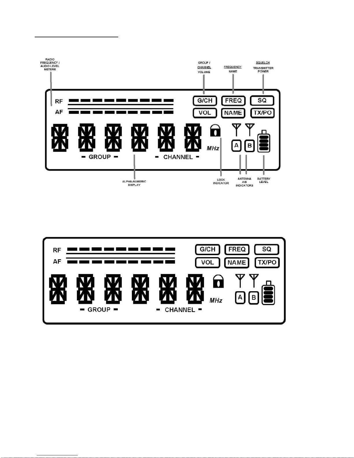
-Once the display is fully illuminated, press the ‘MENU’ button (3), repeatedly, until the “G/CH”
icon is highlighted. The display will read the currently selected “GROUP” number and “CHANNEL”
number. These settings can be changed with the UP/DOWN buttons. It is not necessary to
change these settings in order for the system to work, but they can be changed if any signal
interference is experienced. See the Appendix for Group/Channel/ Frequency assignments.
-To change the ”GROUP” setting, press the “up” button (6) (next to the ‘VOLUME’ knob)
repeatedly until the desired “GROUP” number is displayed. There are 9 Groups available.
-To change the ”CHANNEL” setting, press the “down” button (7) (next to the VOLUME knob)
repeatedly until the desired “CHANNEL” number is displayed. See the Appendix for
Group/Channel correlations.
-Once these settings are made, turn the microphone on and press the ‘SYNC’ button and the
receiver will automatically synchronize with the microphone transmitter at the selected
Group/Channel frequency assignment. The synchronization is successful when the “RF” level
meter shows a signal indication. The “AF” meter will respond to any sounds being picked up by
the microphone. Speaking into the mic should show significant audio level indications on the “AF”
meter. Other indications on the receiver’s display will also indicate “TX” (transmit) and one of the
“A” or “B” antenna indicators will be highlighted showing which antenna has been automatically
selected for the strongest reception.
LOCK / UNLOCK function:
-Holding the ‘MENU’ button down for more than 3 seconds will result in the word “LOCK” being
displayed on the LCD panel. This function stores the unit’s settings at the currently selected
configuration. When the unit is in “LOCK” mode, holding the ‘MENU’ button for 3 seconds will
toggle the function back to the “UNLOCK” mode and parameters can be changed.
The lock icon: will be displayed when the “LOCK” function is active.
7

LCD DISPLAY LEGEND
Display Modes:
_Pressing the ‘MENU’ button repeatedly will change the information displayed in the alpha-
numeric section of the LCD panel showing the five display modes available:
-GROUP/CH
-FREQ (Frequency)
-SQ (Squelch)
-VOL (Mute)
-NAME (Name) will be highlighted in the display with each press of the ‘MENU’ button
8

Function Descriptions:
G/CH – Group / Channel:
This allows for the selection of the Group and the Channel assignment to match the wireless
microphone transmitter being used with the receiver. 9 Groups and 4 Channel selections are
available. The Up button selects the Groups, the Down button selects the Channel
FREQ – Frequency:
This displays the automatically selected frequency.
SQ – Squelch:
This adjusts the level of “squelch” (0-99) which can minimize transmission/reception noise
between the microphone transmitter and the receiver. Level is selected with the Up/Down button.
VOL – Volume:
This mutes and un-mutes the output of the audio from the receiver when either the Up or Down
button is depressed
NAME – Name:
This allows for the custom naming of the microphone and receiver for easy identification. Use the
Up/Down buttons to select the desired letters/numbers. Press the ‘MENU’ button to scroll through
the 6 available characters. The name will be set after the sixth character is entered and the
‘MENU’ button is pressed..
LOCK – :This function locks system settings and the following icon is displayed when active:
(To unlock, hold the “MENU” button for 3 seconds)
Battery status
The following indications relate to the battery level of the two “AA” batteries in the microphone /
transmitter:
It is recommended that batteries be changed if the 25% display is active.
9

Specifications
Microphone / Transmitter Specifications
Housing Material Aluminum Extrusion
Oscillation Mode PLL Synthesized
Carrier Frequency Range UHF 740-752MHz
Stability ±0.005%(-10/50 I I)
Frequency Adjustment Automatic Channel Setting
RF Output Power <10mW
Spurious Emissions <-55dBc
Max. Deviation Range ±68KHz
Maximum Input Level 140dB SPL
Battery 1.5V (AA)×2
Receiver Specifications
Signal to Noise Ratio >105dBA
Total Harmonic Distortion <0.5% at 1KHz
Frequency Response 50Hz~18KHz ±3dB
Functional Distance >100meters (Open area distance)
Main Frame Size EIA standard 1/2-rack unit
Channels Single-channel
Receiver Module True Diversity
Oscillation Mode PLL synthesized
Carrier Frequency Range UHF 780-793MHz
Stability ±0.005%(-10-50
OC)
Bandwidth 13 MHz
Sensitivity 2μV (S/N>12dB 25KHz deviation )
Frequency Interval 250KHz
Available Frequencies 50
Squelch Innovative PiloTone & NoiseLock dual-squelch circuit
Maximum Output Level MIC LEVEL-14dBV/100Ω, LINE LEVEL-4dBV/5KΩ
Output Connectors XLR balanced & ¼”/6.3mm unbalanced phone jack.
AC Power Supply External 90-260VAC
DC Power Supply 1A, 12-15VDC
Dimensions: Inches/ mm 1.7”(H)x8.6”(W)x6.3”(D) / 44(H)×220(W)×160(D)
Product details and specifications subject to change without notice.
10

Regulatory and Licensing
Information
The USX-800H transmitter complies with FCC part 74 rules. Meets the essential requirements
of the European R&TTE Directive 99/5/EC (ETSI EN 300-422 Part 1 & 2, EN 301 489 Parts 1 &
9.) and eligible to carry the CE mark.
The USX-800 receiver complies with FCC part 15 rules. Meets the essential requirements of the
European R&TTE Directive 99/5/EC (ETSI EN 300-422 Part 1 & 2, EN 301 489 Parts 1 & 9.) and
eligible to carry the CE mark.
NOTES:
THE MANUFACTURER IS NOT RESPONSIBLE FOR ANY RADIO OR TV INTERFERENCE
CAUSED BY UNAUTHORIZED MODIFICATIONS TO THIS EQUIPMENT.
SUCH MODIFICATIONS COULD VOID THE USER’S AUTHORITY TO OPERATE THE
EQUIPMENT.
APPENDIX
USX-800 WIRELESS FREQUENCY MATRIX ( F06 code) (MHz)
GROUP
CHANNEL
1 2 3 4
1 740.125 740.125 740.125 740.125
2 741.500 741.950 741.225 740.800
3 743.375 743.500 742.925 741.825
4 744.600 745.675 744.325 743.075
5 746.325 747.400 745.425 745.125
6 748.500 748.625 746.875 746.675
7 750.050 750.500 748.925 747.675
8 751.875 751.875 750.175 749.075
9 751.200 750.775
10 751.875 751.875
11

Wharfedale International LTD.
IAG HOUSE
Sovereign Court, Ermine Business Park,
Huntingdon, Cambs,
PE29 6XU, England
www.wharfedalepro.com
IAG Professional reserves the right to alter or improve specifications without notice.
All rights reserved © 2006 Wharfedale Pro
Wharfedale Pro is a member of the International Audio Group
12
Other manuals for USX 800
2
Table of contents
Other Wharfedale Pro Microphone manuals

Wharfedale Pro
Wharfedale Pro DM 3.0 User manual

Wharfedale Pro
Wharfedale Pro DM-6.0 User manual

Wharfedale Pro
Wharfedale Pro DM 2.0 User manual

Wharfedale Pro
Wharfedale Pro DM4.0 User manual

Wharfedale Pro
Wharfedale Pro KM-1 Guide

Wharfedale Pro
Wharfedale Pro WF-300 User manual

Wharfedale Pro
Wharfedale Pro KM Series Guide

Wharfedale Pro
Wharfedale Pro USX 800 User manual