SOUNDLIGHT 3402B-H Mk1 User manual
OPERATING MANUAL
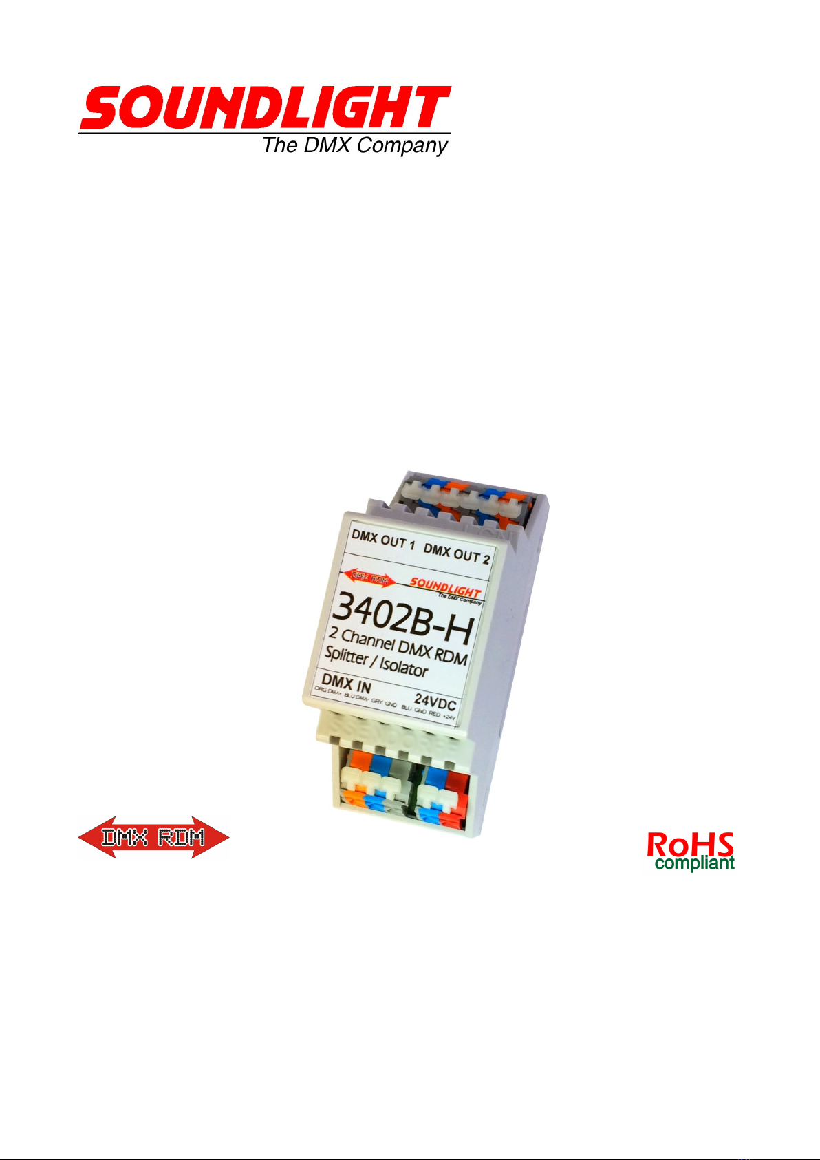
DMX Booster/Splitter 3402B-H Mk1
(C) SOUNDLIGHT 1996-2019 * ALL RIGHTS RESERVED * NO PART OF THIS MANUAL MAY BE RE-
PRODUCED, DUPLICATED OR USED COMMERCIALLY WITHOUT THE PRIOR WRITTEN CONSENT OF
THE OWNER * ALL STATEMENTS WITHIN THIS MANUAL HAVE BEEN CHECKED CAREFULLY AND
ARE BELIEVED TO BE ACCURATE, HOWEVER SOUNDLIGHT DOES NOT ASSUME ANY RESPONSIBI-
LITY FOR ERRORS OR OMISSIONS. * THE USER HAS TO CHECK THE SUITABILITY OF THE EQUIP-
MENT FOR THE INTENDED USE. SOUNDLIGHT EXPRESSLY EXCLUDES ANY RESPONSIBILITY FOR
DAMAGES - DIRECT OR INDIRECT - WHICH MAY OCCUR DUE TO MISUSE, UNPROPER INSTALLA-
TION, WRONG OPERATING CONDITIONS AND NON-COMPLIANCE TO THE INSTRUMENT'S INSTRU-
CTIONS, AS WELL AS IGNORANCE OF EXISTING SAFETY REGULATIONS.
SOUNDLIGHT The DMX Company Bennigser Str. 1 D-30974 Wennigsen Tel +49-5045-912 93-11

Thank you for choosing a SOUNDLIGHT device.
The SOUNDLIGHT DMX Splitter/Booster 3402B-H is a highly sophisticated device, which was designed to
buffer and distribute DMX light control signals complying with USITT DMX-512/1990 or DIN 56930/2, ANSI
E1-11 DMX512-A and ANSI E1-20 dMX RDM, respectively. The unit can be used with all standard light con-
trol systems.
Its special advantages include:
- universal protocol decoding
Recognizes all variants of the protocol as defined by USITT/ESTA/DIN and displays the presence of a
valid DMX signal.
- future-proof
The unit is software controlled an can be adapted to any change in protocol definition;
- unlimited channel count
The number of DMX channels sent or received does not affect the operation of the DMX splitter/booster
3402B-H, since the unit can handle all transmission lengths.
- cost-effective
The SOUNDLIGHT 3402B-H is a cost-effective solution for many purposes.
VERSIONS
The booster / splitter family comprises of these products:
3401A-EP printed circuit board, 1x DMX IN, 1x DMX OUT, opto-isolated line booster
3401B-H DIN rail mount RDM compatible Line Booster, opto-isolated
3402A-EP printed circuit board 1x DMX IN, 2x DMX OUT opto-isolated in/out
3402A-EPD printed circuit board 1x DMX IN, 2x DMX OUT opto-isolated in/out, with Display
3402A-FG stand alone unit 1x DMX IN, 2x DMX OUT opto-isolated
3402A-FGD stand alone unit 1x DMX IN, 2x DMX OUT opto-isolated, with Display
3402B-H DIN rail mount RDM compatible splitter, 2x DMX RDM OUT, opto-isolated, 24VDC
3404LC-H DIN rail mount unit,1x DMX IN, 1x DMX THRU, 4x DMX RDM OUT (buffered/isolated)
3406LC-H DIN rail mount unit,1x DMX IN, 1x DMX THRU, 6x DMX RDM OUT (buffered/isolated)
3408LC-H DIN rail mount unit,1x DMX IN, 1x DMX THRU, 8x DMX RDM OUT (buffered/isolated)
3405A-EP printed circuit board 1x DMX IN, 1x DMX THRU, 5x DMX OUT opto-isolated
3405A-FG 19" rack mount unit 1x DMX IN, 1x DMX THRU, 5x DMX OUT opto-isolated, with Display
3408A-FG 19" rack mount unit 1x DMX RDM IN, 1x DMX THRU, 8x DMX RDM OUT, with Display
3410A-FG 19" rack mount unit 1x DMX IN, 1x DMX THRU, 10x DMX OUT opto-isolated, with Display
NOMENCLATURE
This document uses these indicators:
DANGER ! May cause harm to user and/or equipment
INFO: How to setup your device
INFO: Status information

CONNECTORS
The booster/splitter is using cage clamp terminals for both, input and output. This type of connector is very
reliable, ruggedized and easy to use. Use a flat blade screwdriver only. To open, press lever, insert cable
and release. For stranded wires, we suggest to use (insulated) ferrules.
The DMX data outputs are optically isolated in respect to to the DMX signal input.
DMX INPUT Signal input for control signals according to USITT DMX512/1990 or DIN 56930-2
Pin 1 grey screen / GND
Pin 2 blue DMX - (inverted)
Pin 3 orange DMX + (normal)
DMX OUTPUTS6 outputs, galvanically isolated from the DMX signal input
Pin 1 grey OUT 1 screen / GND
Pin 2 blue OUT 1 DMX - (inverted)
Pin 3 orange OUT 1 DMX + (normal)
Pin 4 grey OUT 2 screen / GND
Pin 5 blue OUT 2 DMX - (inverted)
Pin 6 orange OUT 2 DMX + (normal)
POWER SUPPLY 24VDC approx. 100mA
Pin 1 blue 0.0V
Pin 2 red 24.0V DC
POWER SUPPLY
The power supply is 24VDC. Make sure a stable and regulated DC power source is being used.
Electrical voltage can be dangerous to your health; connections must be carried out by a qualified
technician only.
Make sure the unit has been disconnected from mains before making any other connections to the
booster/splitter. Verify installation before re-applying power.
SIGNAL INDICATORS
Signalling is provided for user guidance.
The state of the booster/splitter interface is signalled by 2 LED indicators.
Color Labelling Description
green SIGNAL Valid DMX signal detected
green POWER Power supply present
DMX IN
DMX / DMX RDM con-
trol signal input
DMX OUTPUTS
2 comman optically iso-
lated outputs in respect
to DMX IN
POWER SUPPLY
24V DC approx. 3W

TECHNICAL DATA
Dimensions 134mm (W) x 67mm (H) x 92 mm (D)
Supply: 24V DC approx. 100mA
DMX IN: 1 Unit Load
DMX OUT: 2 outputs, buffered, optically isolated vs input
DMX Protocol: USITT DMX512/1990, DIN56930-2, ANSI E1-11 DMX512-A, ANSI E1-20 DMX RDM
RDM device: Transparent Device, no UID
Display: 2 LED indicators
Operating Temp: 0C...+50C
Weight: 72 g
Mounting: on 35mm DIN rail, width 2 units
IP rating: IP20, for dry rooms only
Order No.: 3402B-H
DMX RDM PROPERTIES
The 3402B-H can process DMX512, DMX512-A and/or DMX RDM telegrams. In respect to RDM traffic, the
3402B-H acts as "invisible" device, which cannot be discovered or addressed. Please refer to the 3402B-H
product page (see below) for more information regarding RDM properties.
CE CONFORMITY
This DMX splitter/booster is microprocessor controlled and uses high frequency (16 MHz
quartz). The interface has been tested in the EMC lab to comply with EN55015.
To ensure the best performance regarding radiated and conducted emissions please make
sure that shielded data cable is used and the shield is connected properly to the GND pin.
Shield must never make contact to other signal lines.
DISTURBANCES
If a trouble-free operation cannot be guaranteed, disconnect the booster/splitter and secure it against unwan-
ted operation. This is especially necessary, when
- the unit has visible damages;
- the unit does not operate;
- internal parts are loose;
- connection cables show visible damages.
LIMITED WARRANTY
This instrument ist warranted against defects in metarials and workmanship for a period of 24 month, begin-
ning with the date of purchase. The warranty is limited to repair or exchange of the hardware product; no fur-
ther liability is assumed. SOUNDLIGHT is not responsible for damages or for loss of data, sales or profit
which arise from usage or breakdown of the hardware product. In Germany, SOUNDLIGHT will repair or re-
place established defects in hardware, provided that the defective part is sent in, freight paid, through the
responsible dealer along with warranty card and/or sales receipt prior to expiration of warranty.
Warranty is void:
- when modifying or trying to repair the unit without authorisation;
- modification of the circuitry;
- damages by interference of other persons;
- operation which is not in arccordance with the manual;
- connection to wrong voltage or current;
- misuse.

SERVICE
There are no parts within the booster/splitter 3402B-H which require the user's attention. Should your unit re-
quire servicing, please send it to the factory, freight paid.
INTERNET-HOTLINE
Please check our internet domain http://www.soundlight.de for new versions, updates etc. If you have any
PRODUCT INFO
The product info page can be found at: www.soundlight.de/produkte/3402b-h
Foreign language product manauls are available at: www.manuals.soundlight.de
END-OF-LIFETIME
When the end of the lifetime of this product has been reached, ist must be disposed of properly.
Electronic devices must not be placed in domestic waste. They are to be collected by public re-
cycling systems. Consult your local authorities for more information regarding the whereabouts of
your next collection station. SOUNDLIGHT is a WEEE registered company (DE58883929).
Table of contents


