manuals.online logo
Brands
  1. Home
  2. •
  3. Brands
  4. •
  5. Festo
  6. •
  7. Cables And Connectors
  8. •
  9. Festo PAML-CP Series User manual

Festo PAML-CP Series User manual

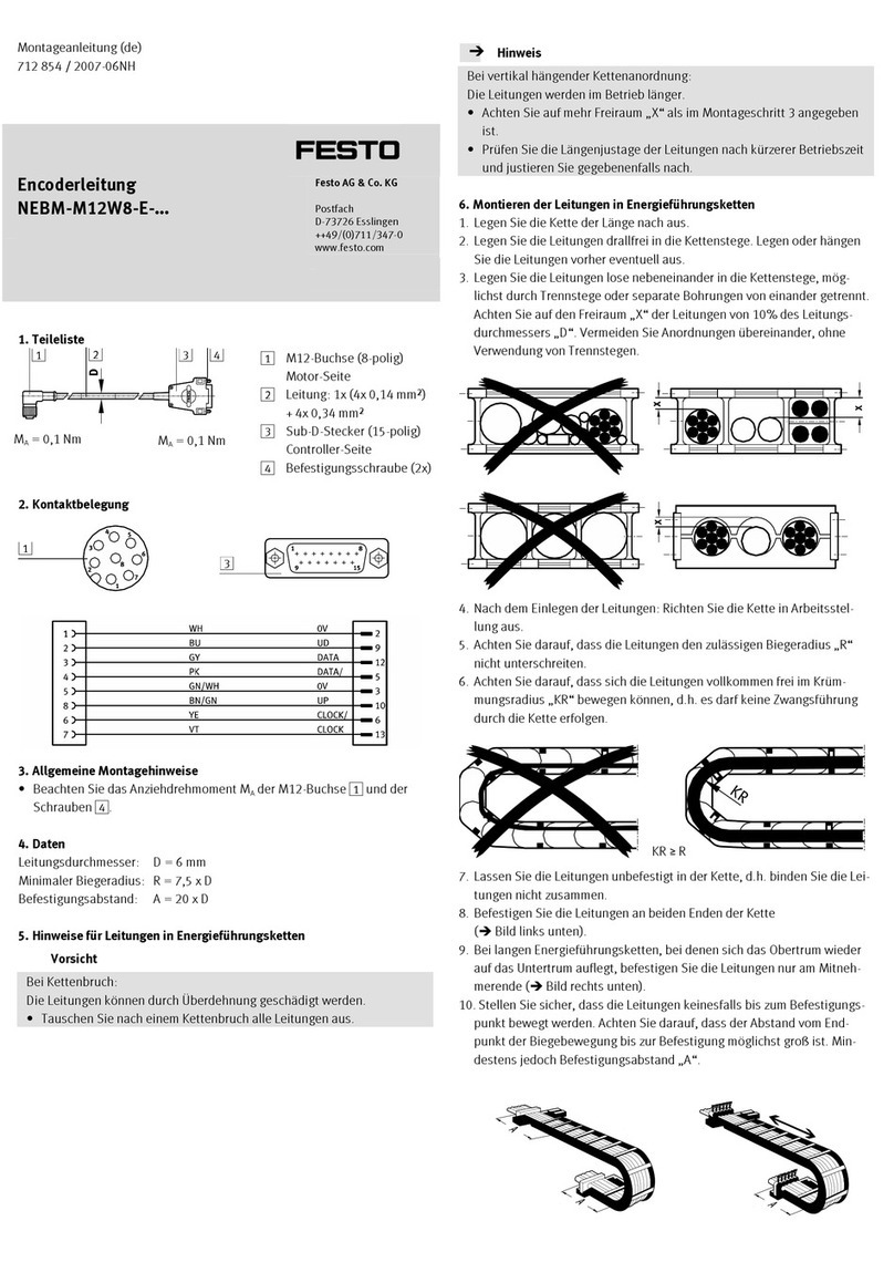
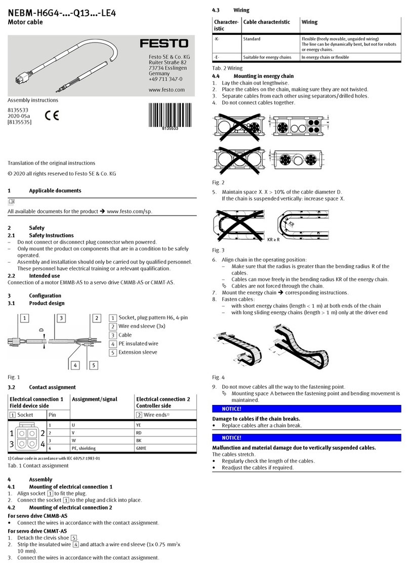
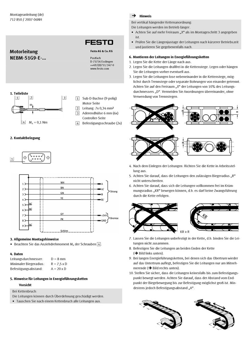
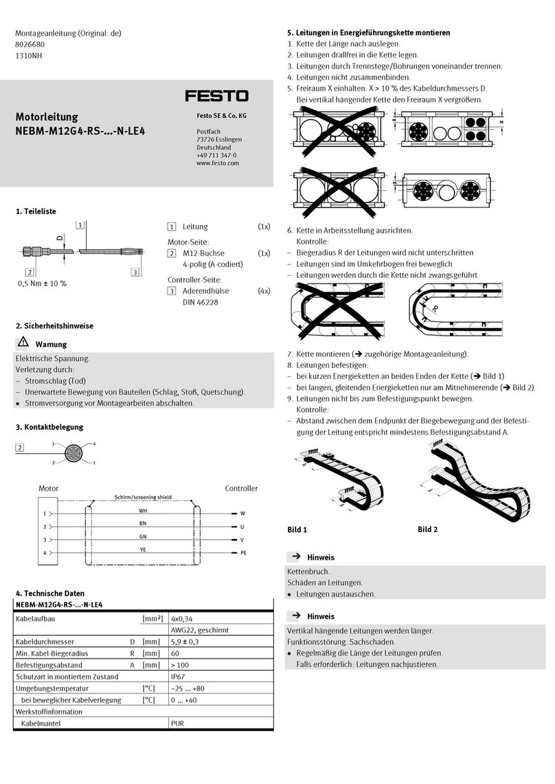
Connecting plate/
module connector PAML-...-186
Festo AG & Co. KG
Ruiter Straße 82
73734 Esslingen
Germany
+49 711 347-0
www.festo.com
Operating instructions
Translation of the original instructions
8082042
2017-11a
[8082044]
For all available product documentation èwww.festo.com/pk
Connecting plate/module connector PAML English.........................
1 Application
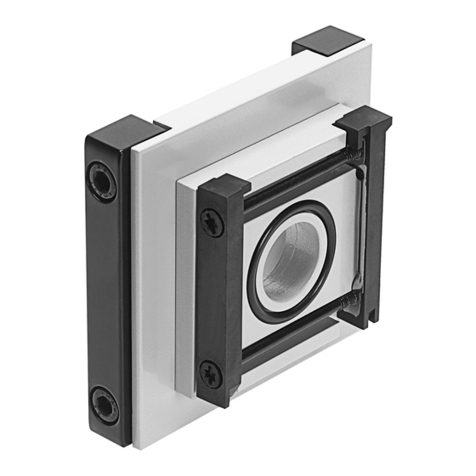
The connecting plates PAML-CP are intended to serve exclusively as adapters for
the pneumatic connection and for tube fastening for in-line installation of service
units. The module connector PAML-MK connects two service unit components with
each other. The rear mounting threads on the connecting plates and module con
nectors are used for wall mounting of individual devices or service units.
 The product may only be used in its original status without unauthorised modi
fications. Only the assembly and commissioning activities described in these
operating instructions are permissible.
 Observe the permissible limit values and specifications.
 Only use the product if it is in an excellent technical status.
 Take into consideration the legal regulations applicable for the location as well as:
– Regulations and standards,
– Regulations of the testing organisations and insurers,
– National specifications.
2 Installation
Note
 Installation should only be conducted by qualified personnel.
Warning
Risk of injury from falling loads.
 Take the weight of an individual device or a service unit into consideration. De
pendent on the design, a mounted service unit can weigh more than 100 kg.
 Only mount the individual device or service unit on a wall or mounting frame
that can support its weight.
 Only mount the individual device or service unit on a flat surface.
Definition
Front plate = front module connector
Rear plate = rear module connector
2.1 Assembly of two service units of the same size with module connector
PAML-MK
 Note the flow direction from 1 to 2.
The numerals on the product housing 1serve as orientation.
1. First, screw both mounting screws through both holes of the front plate 3.
2. Place the seal 4between the service units.
3. Place the front and rear plate 3and 2in the slots of the service units.
4. Turn the screws of the front plate 3into the rear plate 2.
1
2
3
4
40 Nm ±25 %
Fig. 1
2.2 Mounting the connecting plates PAML-CP
 Make sure that the sealing groove, which exists in only one of the two connect
ing plates, lines up with the flat surface on the housing. If mounted correctly, the
stamp number on the connecting plate will be the same as the stamp number on
the housing.
1. Insert the O-rings 5into the designated O-ring grooves.
2. Place the connecting plates in position. Make sure that the connecting plates
are aligned correctly. If mounted correctly, the mounting threads for wall mount
ing 6will point to the rear.
3. Fasten the connecting plates with the appropriate 4 screws M10 7and washers
to the service unit.
4. Observe the max. screw-in depth for the pipe connector, èFig. 2.
Product type ISO 228 Max. screw-in depth
[mm]
Connecting plate PAML-CP G¼12
G1¼20
G1½22
G2 24
G2½26
Fig. 2
27 Nm ±15 %
27 Nm ±15 %
5
6
7
Fig. 3
2.3 Wall mounting
To attach individual devices or service units to the wall or a machine frame, the
M12 threads from the rear panel and the connecting plate can be used.
1. Screw M12 screws 8into all of the rear plates and connecting plates from the
rear. For this purpose, use screws with a minimum screw-in depth of 15 mm and
a maximum screw-in depth of 18 mm. The distance between the screw-in
threads is 186 mm in width and 145 mm in height. Exception for the distance in
width for the distributor block PMBL-186-HP3 with half the normal grid width:
93 mm.
35 Nm ±20 %
8
Fig. 4
3 Dismantling
Warning
Risk of injury from compressed air.
Products under pressure can cause personal injury and material damage.
 Depressurize service unit string and tubing.
Warning
Risk of injury from falling loads.
 Take the weight of an individual device or a service unit into consideration.
Dependent on the design, a mounted service unit can weigh more than 100 kg.
Note
 Dismantling only by qualified personnel.
 If used as intended, the surface temperature can reach 60 °C. Allow the device
to cool off before any maintenance work.
 Depressurize the pneumatic system.
 Remove the existing service unit string.
4 Technical data
PAML -MK -CP
Operating pressure [bar] 0  50
Operating medium Compressed air according to ISO 8573-1:2010 [-:-:-]
Temperature of medium [°C] +5 … +60
Ambient temperature [°C] +5 … +60
Classification in accordance with
EC Pressure Equipment Directive
Category I
CE marking1) According to EC Pressure Equipment Directive
1) Declaration of Conformity èwww.festo.com/sp
Fig. 5

This manual suits for next models

2

Other Festo Cables And Connectors manuals

Festo MS6-9-AMV User manual

Festo

Festo MS6-9-AMV User manual

Festo NEBM-M12G8-E S1G9-V3 Series User manual

Festo

Festo NEBM-M12G8-E S1G9-V3 Series User manual

Festo FEC-KBG7 User manual

Festo

Festo FEC-KBG7 User manual

Festo FBS-SUB-9-GS-2x4POL-B User manual

Festo

Festo FBS-SUB-9-GS-2x4POL-B User manual

Festo CPV14-VI-P Series User manual

Festo

Festo CPV14-VI-P Series User manual

Festo NEBM-M12G4-RS N-LE4 Series User manual

Festo

Festo NEBM-M12G4-RS N-LE4 Series User manual

Festo NEBM-M12W8-E Series User manual

Festo

Festo NEBM-M12W8-E Series User manual

Festo NEBU-M8R3 Series User manual

Festo

Festo NEBU-M8R3 Series User manual

Festo NEBM-S1G9-E-***-N-C1G6 User manual

Festo

Festo NEBM-S1G9-E-***-N-C1G6 User manual

Festo NEBM-M12W8-E Series User manual

Festo

Festo NEBM-M12W8-E Series User manual

Festo NEBC-D12G4-E D12G4-ET Series User manual

Festo

Festo NEBC-D12G4-E D12G4-ET Series User manual

Festo NEBM-M23G6-E Series User manual

Festo

Festo NEBM-M23G6-E Series User manual

Festo YXCL-4 User manual

Festo

Festo YXCL-4 User manual

Festo ZBV Series User manual

Festo

Festo ZBV Series User manual

Festo MS4-6-AMV User manual

Festo

Festo MS4-6-AMV User manual

Festo NEBM-M12G8-E Q5 Series User manual

Festo

Festo NEBM-M12G8-E Q5 Series User manual

Festo NEBM-T1G12-T1G12 Series User manual

Festo

Festo NEBM-T1G12-T1G12 Series User manual

Festo NEBM-M23G6-E Series User manual

Festo

Festo NEBM-M23G6-E Series User manual

Festo NEBM-M23G12-E N-S1G9 Series User manual

Festo

Festo NEBM-M23G12-E N-S1G9 Series User manual

Festo NEBC-U7G10-ES N-S-U5G9 Series User manual

Festo

Festo NEBC-U7G10-ES N-S-U5G9 Series User manual

Festo CTEU-PB Operating and installation instructions

Festo

Festo CTEU-PB Operating and installation instructions

Festo NEBC-U3G5-ES N-S-U1G4 Series User manual

Festo

Festo NEBC-U3G5-ES N-S-U1G4 Series User manual

Festo QSP 10-4 Series User manual

Festo

Festo QSP 10-4 Series User manual

Festo QSP 18 Series User manual

Festo

Festo QSP 18 Series User manual

Popular Cables And Connectors manuals by other brands

Hauppauge WinTV-PVR-150 Kit Connection guide

Hauppauge

Hauppauge WinTV-PVR-150 Kit Connection guide

Lenze EYF Series Mounting instructions

Lenze

Lenze EYF Series Mounting instructions

ADC Category 5e Specification sheet

ADC

ADC Category 5e Specification sheet

NEUTRIK opticalCON HYBRID MED NKO16M-XP-0 Series Cleaning instruction

NEUTRIK

NEUTRIK opticalCON HYBRID MED NKO16M-XP-0 Series Cleaning instruction

Nordval PMPC01 instructions

Nordval

Nordval PMPC01 instructions

TE Connectivity CEELOK FAS-T instruction sheet

TE Connectivity

TE Connectivity CEELOK FAS-T instruction sheet

APP SBS50 Assembly instructions

APP

APP SBS50 Assembly instructions

Tektronix Keithley 4200-RPC-2 Assembly instructions

Tektronix

Tektronix Keithley 4200-RPC-2 Assembly instructions

TracPhone F33 Grounding instructions

TracPhone

TracPhone F33 Grounding instructions

Lenze EYP A Series Mounting instructions

Lenze

Lenze EYP A Series Mounting instructions

Allen-Bradley ControlLogix 1756-CP3 installation instructions

Allen-Bradley

Allen-Bradley ControlLogix 1756-CP3 installation instructions

Aurora ASP-12H-4K user guide

Aurora

Aurora ASP-12H-4K user guide

GTO SW-1500 instructions

GTO

GTO SW-1500 instructions

Sumitomo Lynx-CustomFit LYNX2-LC installation manual

Sumitomo

Sumitomo Lynx-CustomFit LYNX2-LC installation manual

Cadman 4000M OPERATOR'S PARTS and MAINTENANCE MANUAL

Cadman

Cadman 4000M OPERATOR'S PARTS and MAINTENANCE MANUAL

Glenair IRT Series Wiring instructions

Glenair

Glenair IRT Series Wiring instructions

Lindy 20275 user manual

Lindy

Lindy 20275 user manual

Shure UA221 user guide

Shure

Shure UA221 user guide

manuals.online logo
manuals.online logoBrands
  • About & Mission
  • Contact us
  • Privacy Policy
  • Terms and Conditions

Copyright 2025 Manuals.Online. All Rights Reserved.