Soundmachines SILTA User manual
!
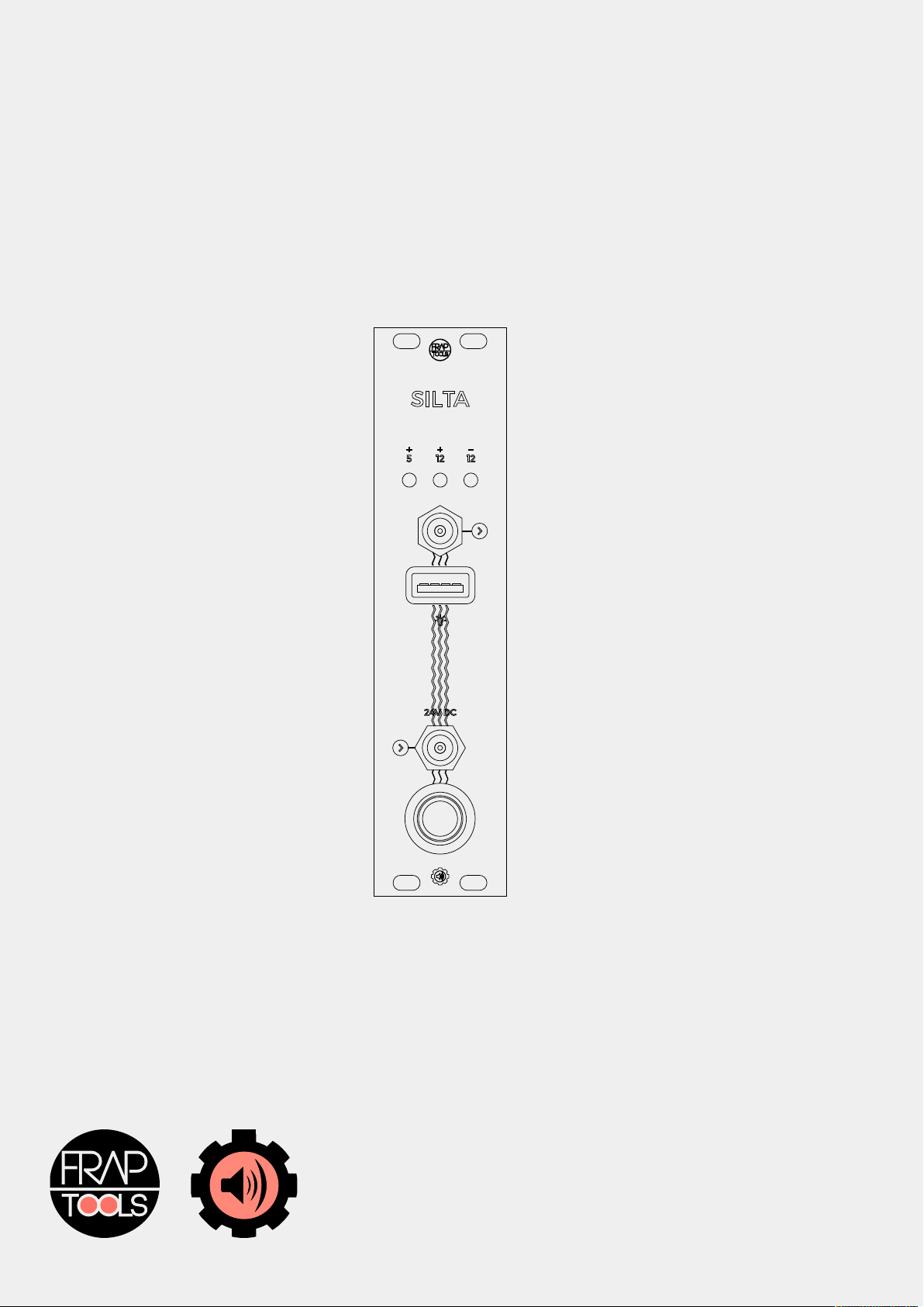
SILTA
made by SoundMachines for Frap Tools

1. SAFETY & WARRANTY!2"
2. WHAT IS SILTA!3"
3. MOUNTING THE MODULE!3"
4. EXTERNAL POWER BRICK!3"
5. POWER UP!3"
6. THE SILTA FLYING BUS!4"
7. USB port!4"
8. MOUNTING THE SILTA POWERKIT FOR UNO!4

1. SAFETY & WARRANTY
This product is covered by the Frap Tools srls (hereinafter “Frap Tools”) warranty, for two (2) years following the date of purchase.
This warranty covers any defect in the manufacturing of this product. This warranty does not cover any damage or malfunction
caused by incorrect use as described in the following instructions.
The warranty covers replacement or repair, as decided by Frap Tools. Please contact customer service at [email protected] for a
return authorization.
Frap Tools warrants that your new Frap Tools product, when purchased at an authorized Frap Tools dealer, shall be free of defects in
materials and workmanship for a period of two (2) years from the original date of purchase. Please contact Frap Tools for
information on warranty and service outside of Europe. During the warranty period, Frap Tools shall, at its sole option, either repair
or replace any product that proves to be defective upon inspection by Frap Tools. Frap Tools reserves the right to update any unit
returned for repair and to change or improve the design of the product at any time without notice. This warranty can be transferred
to anyone who may subsequently purchase the product provided that such transfer is made within the applicable warranty period
and Frap Tools is provided with all of the following items:
•all warranty registration information for the new owner;
•proof of the transfer within thirty (30) days of the transfer purchase, and a photocopy of the original sales receipt.
Warranty coverage shall be determined by Frap Tools in its sole discretion. This is your sole warranty. Service and repair of Frap
Tools products are to be performed only by Frap Tools or an authorized service company. Unauthorized service, repair or
modification will void this warranty.
Please follow the given instructions for use of the device because this will guarantee correct device operation. Due to the fact that
these instructions also include indications concerning Product Liability, it is absolutely imperative that they be read carefully. Any
claim for defect will be rejected if one or more of the following points is not observed. Disregard of the instructions can void the
warranty.
The device may only be used for the purpose described in this operating manual. Due to safety reasons, the device must never be
used for purposes not described in this manual. If you are not sure about the intended purpose of the device please contact an
expert or Frap Tools at the email address above.
Do not use or store the device in humid places. Avoid contact with any kind of liquid.
Do not touch any component of the device when it is power or connected to any power source.
Do not place the device on unstable carts, stands, tripods, tables, or other surfaces, or on surfaces which are not perfectly plane.
This may cause the device to fall which could result in human injury, property damage and/or improper functioning of the device
itself.
The device is designed for use only when safely and tightly mounted in a proper eurorack case, made of non flammable materials. If
you are not sure about the intended purpose of the device please contact an expert or Frap Tools at the email address above..
Do not ever leave the device switched on when not in use.
To prevent fire, never place any type of candle, or fire, or other source of heat on or near the device.
Transport the device only in the original box with original packaging or when safely and tightly mounted in a proper eurorack case,
and handle it with care. Never let the device fall or topple. Make sure that during transport and while in use the device and its case,
have a proper stand and does not fall, slip or turn over because of potential human injury to persons and/or property damage. Any
damage from physical abuse such as dropping the unit, impact from hard objects or damage to external components as a result of
negligence will void this warranty.
Never subject the device to temperatures above +40°C or below 0°C. Before operation, also verify operating temperature ranges of
all the modules and the power boards in use. Do not keep or leave the case that hosts the device, or the device itself near heat
sources.
Any modification must be carried out only by Frap Tools or an authorized service company. The device may not be modified in any
way by any parties not expressly authorized by Frap Tools. Any repair, modification, tampering, or attempted repair made by
unauthorized personnel will void this warranty.
Frap Tools can not be held responsible in any way for problems to persons or property or to the device itself, if the device is installed
improperly, or if it is improperly used, maintained, or stored.
Any device shipped to Frap Tools for return, exchange, warranty repair, update, or examination must be sent in its original
packaging! Any other deliveries will be rejected. Therefore, you should keep the original packaging, and all the technical
documentation including this manual. The device must be shipped only with the original packaging. As specified on the product
box, this box is not intended for shipment: if you bought the device directly at a physical reseller's shop, you should put the device
in the original packaging and put the packaging in a proper larger box with proper packaging destined for shipping. If you received
the device via carrier or any post service, it should have come with a proper double box packaging.
All non-warranty services are subject to a minimum fee of €50.00+VAT (within the European Union). The customer must pay for
shipping to Frap Tools, Frap Tools will cover return shipping costs.
To insure long life for the power supply, you should be aware of the total power consumption of your system. This is determined by
adding together the amount of current used by each of your modules. Please refer to the power consumption guides provided by
your modules’ manufacturer(s).
user manual rev 1 May 2016
Page !of !2 18

The SILTA is designed to power systems ranging from 3U to 6U up to 126HP. However, since there are so much different modules
on the market with such different amount of current used, it is imperative to double check the power consumption of your modules
before to connect them to SILTA, being sure that the sum of the current used by the all modules does not exceed any limit of power
provided by SILTA. This is imperative in order to do not overload the SILTA power or system or its external adapter.
It is important to note that the front panel of the SILTA 6HP eurorack power module may get warm. Please do not be alarmed, as
this is normal and is part of its standard operation.
Do not install the SILTA directly to any flammable material if not checked and approved by Frap Tools: this will cause the SILTA to
overheat.
WARNING: The internal components of any SILTA power module can get very hot. Do not touch the internal components while it is
connected and/or powered.
Please be sure to check the temperature of your power brick about 20 minutes after power up. Make sure to do that each time you
add more modules to your system. If the power brick is very hot to the touch, it is likely being overloaded, this will shorten the life of
your power brick.
Shut down your equipment immediately if it produces smoke, a strange odor, or unusual noise. Continued use may lead to fire.
Immediately unplug the equipment and contact your dealer or Frap Tools at the address above for advice.
Never attempt to repair this product yourself. Improper repair work can be dangerous. Never disassemble or modify this product.
Tampering with this product may result in injury or fire and will void your warranty.
Be sure to use the external power brick provided by Frap Tools. Connection to an improper power source may cause fire.!
Do not allow foreign matter to fall into the equipment. Penetration by foreign objects may lead to fire.
If water or other liquid spills into this equipment, do not continue to use it. Continued use may lead to fire. Unplug the power cord
immediately and contact your dealer or Frap Tools at the address above for advice.
2. WHAT IS SILTA
SILTA is a clean, regulated, and protected power solution for eurorack systems. The SILTA 6HP eurorack power module provides up
to:
•1.25A @ +12V
•1.25A @ -12V
•1.5A @ +5V
The SILTA power system included in the SILTA powered UNO foldable cases provides up to:
•3.75A @ +12V
•3.75A @ -12V
•1.5A @ +5V - in the middle row
3. MOUNTING THE MODULE
Make sure the 16 pin IDC female connector on the SILTA flying bus is connected to the male connector on the SILTA board.
Install the 6HP module in your case keeping the push button on the outside, using all the 4 screws provided to be sure the module
is safely and tightly connected to your eurorack case.
Then connect your modules to the SILTA flying bus, as suggested by the modules’ manufacturer(s). The SILTA flying bus use
orientation marked male connectors so be extremely sure to connect all your modules in the right way. Frap Tools is not responsible
of any damage caused by any wrong cable connection.
4. EXTERNAL POWER BRICK
To get the best results, we suggest to use only our 24VDC power brick provided with your SILTA system. Other power bricks may
work just fine, but we cannot guarantee them. Using an incorrect power supply will void any warranty on this product.
Some small SILTA systems, as the standalone SILTA 6HP eurorack module, does not include the power brick because you may use
the module daisy chained with a 2.5 mm standard DC-DC power cable (sold separately) to other SILTA 6HP eurorack modules to
expand your system power capabilities, and making two power bricks unnecessary. In that case just be sure to get at least one of
our power bricks to power up to 3 standalone SILTA 6HP eurorack modules.
5. POWER UP
Connect the power brick 24VDC power adaptor to the input plug on the SILTA module labeled ‘24V DC’ at the base of the module.
Pushing the black latching switch when the power brick is connected will power the SILTA on.
When the SILTA is powered on, you’ll see that the 3 LEDs used for the +5V, +12V and -12V lights up. This is helpful to understand if
each rail is working properly.
An internal circuit creates regulated +12V (1.25A), -12V (1.25A) and +5V (1.5A) that supply:
•USB MIDI devices connected via USB such as an iPad, USB MIDI keyboards, midi controllers and USB goose-neck lamps;
user manual rev 1 May 2016
Page !of !3 18

•powering +5V rail at Doepfer A-100 bus 16-pin IDC-connector via flying ribbon cables or connecting third-party bus-boards.
Taking into account the PSU has general efficiency at roundabout 90% (differs on different rails and the DC voltage applied).
6. THE SILTA FLYING BUS
The SILTA flying bus comes always tested to ensure you that everything works as expected and no shorts happens.
The standard SILTA flying bus, provided within the SILTA 6HP eurorack module is designed to power up a single Frap Tools PLUS
42HP case. In case of need, you can extend you SILTA flying bus with other SILTA flying busses, simply purchase another SILTA
Flying Bus and connect the female of the new cable to the last male connector on the existing SILTA Flying Bus.
Please note: As you keep adding more modules to your system make sure to monitor the heat of the SILTA power module and the
power adapter in order to do not overheat them as they might get damage if overloaded.
7. USB port
Output power consumption to your USB device is limited to 0.5A to protect against short circuits.
WARNING: 500mA are enough in order to connect lamps or other equipment that require a powered USB port. It is possible but not
recommended to charge other devices like cell phones. However be aware: typical mobile chargers require 1200-2100mA for
optimal (fast) charge, so charging external devices from the SILTA 6HP eurorack module may increase the temperature of the
module. An iPad, nowadays, requires at least 1200mA (suggested 2100 mA) current to show an active charging process. Since the
output of the SILTA USB +5V current is less than the iPad requires it still WILL charge it, however it may require more time than it
takes with original iPad charger and will show “NOT CHARGING” on the screen. In general, charging operation requires a high
current even for a small cell phone, so it is recommended to use your original or external chargers and use the powered USB output
for devices or lamp.
8. MOUNTING THE SILTA POWERKIT FOR UNO
WARNING: The mounting of power boards must be done by competent staff. Frap Tools can not be held responsible in any way for
human injury or material damage resulting from incorrect installation, mounting, or cabling.
First, unmount the main PSU holder and the two bus holder.
"
user manual rev 1 May 2016
Page !of !4 18
Table of contents
Other Soundmachines Recording Equipment manuals

 User manual")


