Soundoff Signal pinnacle Quick start guide
OWNER’S MANUAL &
INSTALLATION INSTRUCTIONS
EPL9000 9.10

TABLE OF CONTENTS
PAGE CONTENT
3 TECHNICAL SPECIFICATIONS
4 PRE-INSTALLATION
5 PINNACLE BASICS
6 FIXED HEIGHT BRACKETS AND HOOK MOUNTING
7 FIXED HEIGHT BRACKETS PERMANENT MOUNTING
8-10 ADJUSTABLE HEIGHT BRACKETS AND HOOK MOUNTING
10-11 ELECTRICAL INSTALLATION
12-13 BREAKOUT BOX
13 FLASH PATTERNS AND CONNECTOR INSTRUCTIONS
14 CONTROLLER AND WIRE HARNESS INSTRUCTIONS
15 PINNACLE TROUBLESHOOTING
16 REPLACEMENT PARTS
17 PRODUCT MAINTENANCE
BACK WARRANTIES AND POLICIES
Page 2

Technical SPECIFICATIONS
Input Voltage 10-16Vdc
Current Draw (Amps)
Average Peak Power Consumption
(Watts)
Inboard Module (ea): 0.5Amps @ 12.8Vdc 1.0Amps @ 12.8Vdc 6.4
Corner Module (ea): 1.0Amps @ 12.8Vdc 2.0Amps @ 12.8Vdc 12.8
Takedown Module (ea): 0.5Amps @ 12.8Vdc 1.0Amps @ 12.8Vdc 6.4
Alley Light Module (ea): 0.33Amps @ 12.8Vdc 0.65Amps @ 12.8Vdc 4.2
Average = Flashing Peak = 100% Steady ON
Reverse Polarity: Fuse Protected
Load Dump: Protected
Wiring: Power Cable 15ft 10AWG Wires, (+) RED, (-) BLK
Data Cable 15ft RJ-45 Type
Number of LEDs:
Inboard Module (ea) 6 Gen3 LEDs
Corner Module (ea) 12 Gen3 LEDs
Takedown Module (ea) 6 Gen3 LEDs
Alley Light Module (ea) 1 Multi Chip Gen3 LED
Operating Temperature: -40°C to +65°C
Light output:
Blue LED 30 Lumens minimum per LED
Red LED 50 Lumens minimum per LED
White LED 100 Lumens minimum per LED
White Multichip LED 400 Lumens minimum per LED
Amber LED 45 Lumens minimum per LED
Green LED 40 Lumens minimum per LED
Life: 50K+ hours
Optical Distribution:
Inboard Module (ea) 20° Vert. x 90° Horiz. Angle
Corner Module (ea) 20° Vert. x 120° Horiz. Anle
Takedown Module (ea) 20° Beam Angle
Alley Light Module (ea) 20° Beam Angle
Moisture Protection: IP66 sealed construction
Outer Lens: Polycarbonate with UV Protection
Mounting Bolt: n3/16” Stainless / A2
Dimensions:
36” Lightbar 35.4“L x 10.0”W x 2.9“H (end), 2.2”H (interior)
42” Lightbar 41.7“L x 10.0”W x 2.9“H (end), 2.2”H (interior)
48” Lightbar 48.0“L x 10.0”W x 2.9“H (end), 2.2”H (interior)
54” Lightbar 54.3“L x 10.0”W x 2.9“H (end), 2.2”H (interior)
60” Lightbar 60.7“L x 10.0”W x 2.9“H (end), 2.2”H (interior)
72” Lightbar 73.5“L x 10.0”W x 2.9“H (end), 2.2”H (interior)
*Based on configuration see page 12.
Page 3
Unpack box:
1. Remove the light bar and packaging.
2. Save packaging for later shipping.
3. Check components/contents.
4. Please reference this instruction manual for
proper wiring and installation.
Tools Required for Installation:
5/32” Allen Driver
7/16” Socket with ratchet
T-25 Torx Driver
Phillips Head Screwdriver
Electric Drill with #30 (.128 dia.) drill bit
1 1/4” Hole Saw
Components/Contents
Standard Equipment
1- PINNACLE Lightbar
1- Roof Side Cable Grommet (cable specific)
Controller
1- Breakout Box (DSC Option)
1- Wire Harness
Optional Mounting Kits
2- Adjustable Height Mounting Brackets (OR)
2- Fixed Height Mounting Brackets
1- Specific Vehicle Hook w/ Hardware Kit (OR)
1- Specific Mounting Hardware Kit
**Kits will vary with each bar
WARNING - DRILLING ANY HOLES INTO THE LIGHTBAR IS NOT RECOMMENDED! THE
RISK OF DAMAGING INTERNAL COMPONENTS AND THE RESULTING FAILURE OF THE
LIGHTBAR WILL VOID ANY WARRANTY OF THIS PRODUCT.
IMPORTANT NOTICE TO INSTALLER: Make sure to read and understand all instructions and warnings before
proceeding with the installation of this product. Ensure that the manual and any warning cards are delivered to
the end user of this equipment. Proper installation of the lightbar requires the installer to have a thorough
knowledge of automotive electronics, systems, and procedures. Lightbars provide an essential function of an
effective visual warning system. The use of the lightbar does not insure that all drivers can or will abide by or
react to an emergency warning signal, especially at high rates of speeds or long distances. The operator of the
vehicle must never take the right of way for granted and it is the operator’s responsibility to proceed safely.
The effectiveness of the this lightbar is highly dependant on the correct mounting and wiring. The installer
must read and follow the manufacturer’s installation instructions and warnings in the manual. The vehicle
operator should verify daily that the lightbar is securely fastened to the vehicle and properly functioning before
operating vehicle. The lightbar is intended for use by authorized personnel only. It is the user’s responsibility
to ensure they understand and operate the emergency warning devices in compliance with the applicable city,
state and federal laws and regulations. (SoundOff Signal assumes no liability for any loss resulting from the
use of this warning device.)
PRE-INSTALLATION
At anytime during your installation process, feel free to call our technical support line at
1-800-338-7337. Press #4 to skip automated message. You can also visit our website at
Page 4
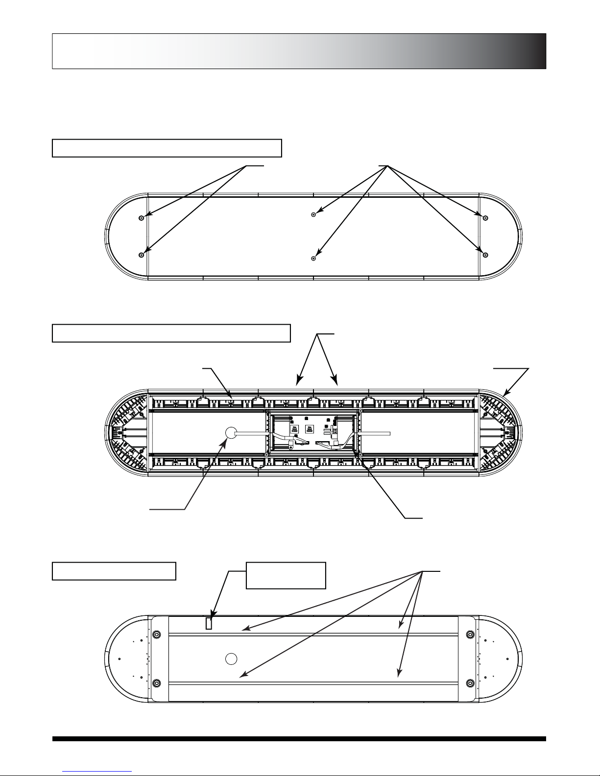
6 TOP COVER SCREWS
FRONT
REAR
MODEL NUMBER
SERIAL NUMBER
This is a basic configuration showing many of the features offered. Your PINNACLE may
have a different configuration. This diagram should only be used as a reference.
PINNACLE BASICS
INBOARD LED MODULES CORNER LED MODULES
WIRE EXIT
TAKE DOWN MODULES
ELECTRICAL ENCLOSURE
CARRIAGE BOLTS
FOR MOUNTING
BRACKETS IN CHANNELS
BOTTOM VIEW
TOP VIEW WITH COVER OFF
TOP VIEW WITH COVER ON
Page 5
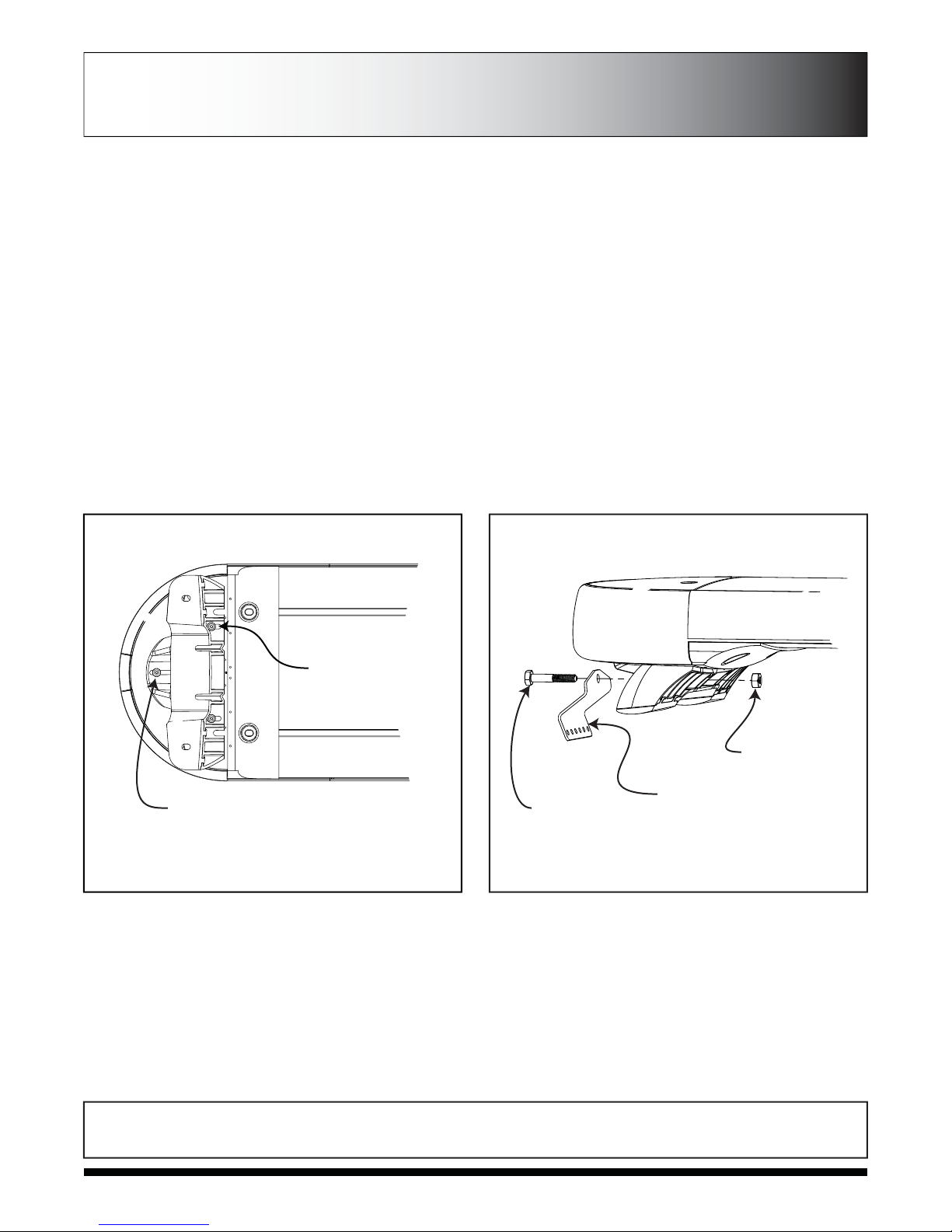
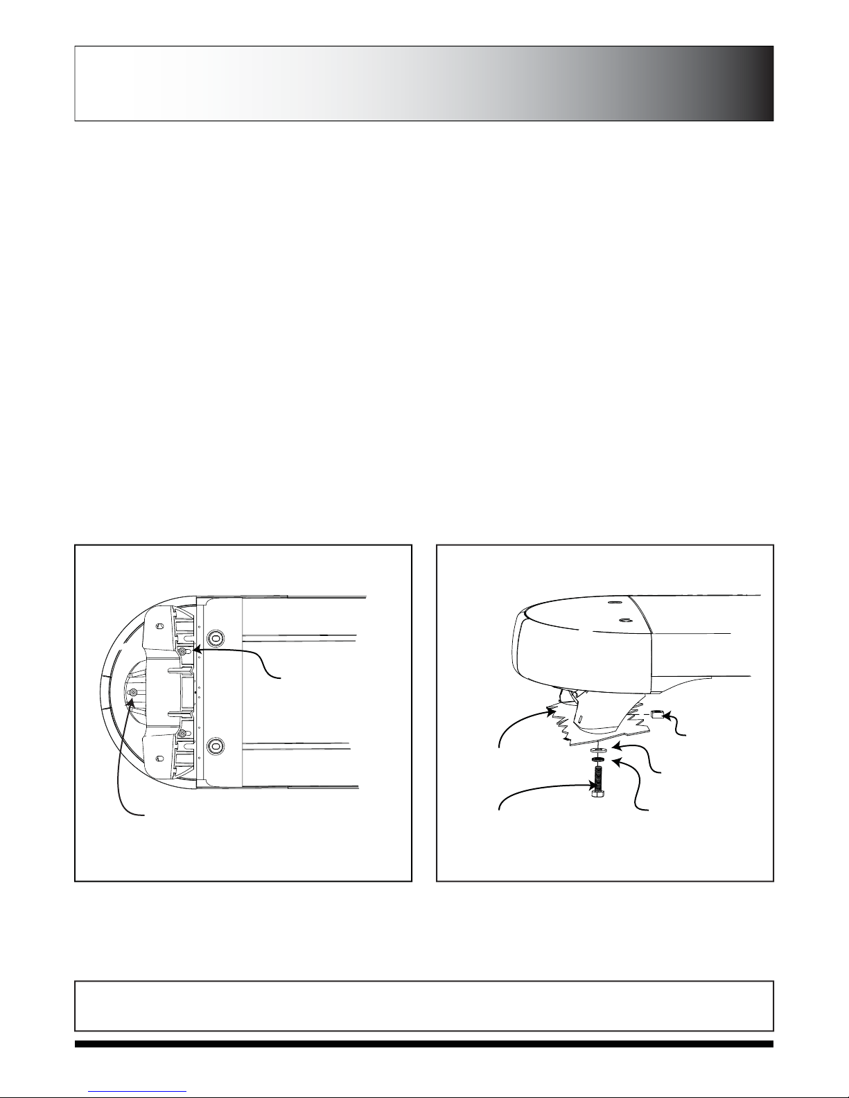
1. Mount fixed height brackets (See Figure 1) using supplied (3) T25 torx screws on each side. Temporarily place the lightbar in
it’s correct position on the roof of the vehicle. The bar should be positioned about the center line of the “B” pillar.
2. Based on the bar’s position, determine wire entry into vehicle. Mark location for later use. Note: Take into consideration the
location of any structural, airbag, or heating and cooling system components that can be in the way of the the wire entry point
or wire routing.
3. Install supplied vehicle specific hook brackets using supplied 1/4”-20 x 2.5 Hex Head bolts and Nylon Locking Nuts onto the bar
mounting foot as shown in Figure 2. Nut will nest into molded socket to prevent turning and improve ease of installation. It’s
recommended that you position the nut into the foot and tap it slightly with a hammer to seat it into the cast foot prior to placing
the bar on the roof. This will make installation easier.
4. Adjust fixed height bracket position on the Lightbar by loosening the (3) T25 Torx Screws on each side (See Figure 1). Be sure
that there is enough clearance between fixed height brackets and vehicle specific brackets to allow for tensioning to roof. When
the correct position is found, tighten T25 torx screws that attach fixed height bracket to lightbar base end plates.
5. Using the vehicle specific hook brackets as a template, drill 4 pilot holes using a #30 (.128 dia.) drill bit on each side of the
vehicle.
6. Secure each vehicle specific hook bracket by using the 8 supplied #8 x 1/2” Truss Head Sheet metal screws on each side.
7. Tighten each vehicle specfic hook bracket by turning the 1/4”-20 x 2.5 Hex head bolt clockwise until bar is snug and no side to
side or fore to aft movement occurs.
8. Route cables into vehicle. Use supplied rubber grommet in roof for sealing/protection of wires. It is recommended that silicone
be placed around grommet to ensure roof sealing.
WARNING - ROUTE WIRES ONLY IN LOCATIONS THAT ARE NOT SUBJECTED TO POTENTIAL WEAR. MAKE SURE TO
AVOID ROUTING WIRES IN THE DEPLOYMENT AREA OF YOUR AIR BAG. REFER TO YOUR VEHICLE’S OWNER’S
MANUAL FOR AIR BAG DEPLOYMENT ZONES.
FIXED HEIGHT BRACKETS AND HOOK MOUNTING
1/4”-20 x 2.5”
Hex Head Bolt
Vehicle Specific Hook Bracket
1/4”-20 Nylon
Locking Hex Nut
Slots for
adjustablitlity
for correct roof fit
Loosen T25 Torx Screws
to adjust brackets
FIGURE 1 FIGURE 2
Page 6
FIXED HEIGHT BRACKETS PERMANENT
MOUNTING
1. Locate the permanent hardware kit that is included. Kit will include (4) 1/4”-20 x 1“ hex head screws, (4) flat washers, (4) lock
washers, (4) square nuts, and (6) T25 Torx Screws.
2. Attach fixed height brackets to lightbar using T25 Torx Screws. Brackets should be adjusted to identical positions at both ends
of lightbar. See Figure 1.
3. Position the lightbar on the vehicle roof in the desired mounting location. The recommended location is directly above the B-
Pillars. This is the strongest part of the roof. Make sure that the bar is centered on the vehicle left to right. Adjust bracket
location on lightbar base end castings if needed.
4. Mark the location for the (4) holes that need to be drilled through the roof that will attach the fixed height brackets to the roof.
5. Determine the best location for cable entry depending on the configuration of your bar. Using a 1-1/4” hole saw, drill hole in the
marked location. Be mindful that you do not drill through any roof support members or the interior headliner.
6. Using a 5/16” drill bit, drill the 4 holes in the locations that you marked in step 4. Clean and debur each hole.
7. Attach the lightbar to the vehicle using the supplied hardware. Use (1) flat washer and locking nut for each bolt. You should
have a total of 4 bolts attaching the lightbar to the roof of the vehicle. See Figure 2 for details. It is recommended that you add
silicone around the hole to ensure roof sealing.
8. Route cables into vehicle. Use supplied rubber grommet in roof for the sealing/protection of wires. It is recommended that
silicone be placed around the grommet to ensure roof sealing.
WARNING - ROUTE WIRES ONLY IN LOCATIONS THAT ARE NOT SUBJECTED TO POTENTIAL WEAR. MAKE SURE TO
AVOID ROUTING WIRES IN THE DEPLOYMENT AREA OF YOUR AIR BAG. REFER TO YOUR VEHICLE’S OWNER’S
MANUAL FOR AIR BAG DEPLOYMENT ZONES.
Slots for
adjustablitlity
for correct roof fit
Loosen T25 Torx Screws
to adjust brackets
FIGURE 1
Roof Cut-away
4x 1/4”-20 x 1”
Hex Head Screw
4x 1/4” Lock
Washers
4x 1/4” Flat
Washers
4x 1/4” -20
Square Nuts
FIGURE 2
Page 7

ADJUSTABLE RUBBER FEET
HEIGHT ADJUSTMENT
SCREWS
HEIGHT & ROOF ANGLE ADJUSTMENT SCREWS
VEHICLE SPECIFIC BRACKET
ADJUSTMENT SCREW
VEHICLE
SPECIFIC
BRACKET
PIVOT
ARM
FRONT TO BACK TILT ADJUSTMENT SCREWS
ADJUSTABLE HEIGHT BRACKETS AND HOOK MOUNTING
Page 8

1. Attach vehicle specific bracket to adjustable mounting bracket. 1 1/2” Allen drive screw must be placed “underneath” djustable
mounting bracket (See Figure 1). Allen drive screw will be accessible through hole in front of adjustable bracket. Square nut
must be placed in front of vehicle specific bracket. Place 1/4“ lockwasher between square nut and vehicle specific hook
bracket. See Figure 1 for details. To hold bracket in place, use provided hardware: 1 flat washer, 1 lock washer and 3/8” Allen
drive screw per slot (as shown in Figure 1).
2. Attach mounting brackets to bar using the carriage bolts pre-installed on the bar. Use two lockwashers and a acorn nut per bolt.
Leave acorn nuts loose so that the bracket has the ability to slide to fit your specific vehicle application. When choosing the
placement for the mounting bracket, consider the cable routing and the risk of pinching wires or anything that can lead to cable
failure. See Figure 2 for details.
3. Position bar on roof about center line of “B” pillar. Determine final location of adjustable mounting brackets for vehicle
application and ensure bar is centered about brackets and vehicle. Determine and mark off locations for mounting screws
through vehicle specific bracket into roof. Determine location for wire entry into vehicle.
4. Determine the height of bar in relationship to the roof that best suits your application. Height of bar can be adjusted by
loosening 4 allen drive screws that fasten pivot arm to either end. To simplify this procedure we recommend cutting 2 wood
blocks to your preferred height to set gap height between roof and bar. Also be sure that adjustable height bracket feet are
sitting flat on vehicle roof. See Figure 3.
5. After position of bar is determined. Tighten tilt and height adjustment screws (shown on page 5). Also tighten acorn nuts
attaching adjustable mounting bracket to bar.
6. Drill 4 holes using a #30 (.128 dia.) drill bit on each side of vehicle that were marked in Step 5. Be careful not to damage
weather stripping on vehicle.
7. Using 1 1/4” hole saw, drill hole in marked location on roof for cable routing. Be mindful that you do not drill through any roof
support members or interior head liner. Clean and debur hole.
8. Secure each vehicle specific bracket by using 4 supplied #8 x 1/2” truss head screws.
9. When required, adjust front to back tilt to make bar parallel with road for best optical range. 5/32“ allen drive adjustment
screws are located above each mounting foot in the mounting bracket base. Adjustment screws must be turned
counter-clockwise to raise either front or back of bar.
SQUARE NUT
1/4-20 X 1.5” SCREW
FIGURE 1
VEHICLE SPECIFIC BRACKET
1/4-20 X 3/8 SCREW
1/4” TOOTH LOCKWASHER
1/4” FLAT WASHER
TOOTH LOCKWASHER
LOCKWASHER
ACORN NUT
GASKET
FIGURE 2
ADJUSTABLE HEIGHT BRACKETS AND HOOK MOUNTING
Page 9

10. Tighten vehicle attachment brackets to roof by turning 5/32” Allen driver in COUNTER-CLOCKWISE ROTATION. Depending on
your desired height, you may need to cut down your allen wrench to fit between the bar and the mounting bracket. Or use a micro
drive gear wrench and 1/4” shank with 5/32” allen bit.
11. Route cables into vehicle. Use supplied rubber grommet in roof for sealing/protection of wires. It is recommended that silicone
be placed around grommet to ensure roof sealing.
12. Route cable down through the “B” pillar and towards switch panel. Refer to the instructions included with your switch for
switch wiring information.
WARNING - ROUTE WIRES ONLY IN LOCATIONS THAT ARE NOT SUBJECTED TO POTENTIAL WEAR.
MAKE SURE TO AVOID ROUTING WIRES IN THE DEPLOYMENT AREA OF YOUR AIR BAG. REFER TO
YOUR VEHICLE OWNER’S MANUAL FOR AIR BAG DEPLOYMENT ZONES
WARNING - ALL CUSTOMER SUPPLIED POWER WIRES CONNECTING TO THE POSITIVE (+) OR
NEGATIVE (-) BATTERY TERMINAL OR LOCAL CHASSIS GROUND (-) MUST BE SIZED TO SUPPLY AT
LEAST 125% OF THE MAXIMUM CURRENT AND PROPERLY FUSED AT THE POWER SOURCE WITH
APPROPRIATELY RATED FUSE.
Power Cable:
1. Route lightbar power cables as close to vehicles power source (battery) as possible.
ELECTRICAL INSTALLATION
Featured Highlights:
Mode Select: The PINNACLE Lightbar is equipped with 2 selectable pattern configuration modes via the Mode Select Input. Default
is Mode 1 where the input is floating, Mode 2 is in use when the input activated. This feature allows 2 complete sets of patterns to
be programmed into the Lightbar's non-volatile memory. Once programming configuration is complete, the Mode can be changed
“on-the-fly” by an activation switch.
Cruise Mode: Allows the user to program any Light Head Group(s) to “Glow” when this feature is activated.
Directional Arrow Built-in: If the lightbar was purchased with a directional arrow, the directional controller is built-in w/ 4 arrow
patterns for each direction and 9 warning patterns for warming functions.
ELECTRICAL INSTALLATION
LOCATION FOR MOUNTING
SCREWS TO ROOF
FEET MUST SIT
FLAT ON ROOF
TIGHTEN BRACKETS
TO ROOF BY COUNTER
CLOCKWISE ROTATION
REPRESENTS
VEHICLE ROOF
CENTER ABOUT “B” PILLAR
FRONT-BACK
TILT ADJUSTMENT
SCREWS
WARNING - CARE MUST BE TAKEN WHEN DRILLING THROUGH THE ROOF OF THE VEHICLE NOT TO
DRILL INTO ANY EXISTING WIRING AND NOT TO DRILL THROUGH THE HEADLINER OR SUPPORT
MEMBERS OF THE VEHICLE. CHECK BOTH SIDES OF THE MOUNTING SERVICE PRIOR TO DRILLING.
DE-BURR ANY HOLES AND REMOVE ANY METAL SHARDS OR REMNANTS. INSTALL GROMMETS
INTO ALL WIRE PASSAGE HOLES.
FIGURE 3
Page 10

IMPORTANT: When passing cables through firewall or other sheet
metal, insert grommet to protect the cable!
2. Install a 40Amp Fuse (customer supplied) to the end of the RED wire of the Lightbar Power Cable.
a. Remove the fuse before connecting any wires to the battery.
b. DO NOT USE CIRCUIT BREAKER OR FUSIBLE LINK.
3. Connect the other end of the Fuse to the POSITIVE (+) terminal of the battery.
a. Do NOT use any more than 2ft of wire between the battery terminal and the fuse and ensure the wire is protected
and secured from being cut into; this is non-fused wire.
4. Connect the BLACK wire to the factory chassis ground right next to the battery.
Control (Data) Cable:
1. Route Lightbar Control Cable to the location where all controlling equipment will be, i.e. switch box, center console area.
2. Locate the Breakout Box in the same area to connect jumpers from the switching equipment to the breakout box.
NOTE: Power is supplied to Breakout Box through data cable, no additional power connections necessary.
Initial Power up Test:
1. Insert 40Amp Fuse into Fuse Holder.
2. Plug data jack into Data 1 connector of the breakout box (Data 2 may also be used, but is for future use.)
3. Observe the GREEN Data Link indicator LED on the Breakout Box; the LED will turn steady ON about 15 seconds after main
power is connected
4. When GREEN LED is steady ON (see below), the lightbar is ready to be configured.
Low Power (Standby) Mode
If there is no input to the breakout box for 15 seconds, the lightbar will go into a “standby” mode. The standby mode is a low power mode that is
used to extend the life of your battery. The green light will turn off when the lightbar enters standby mode. The red light will flash every five
seconds showing that it has power. The lightbar will awaken from the standby mode if any input is activated on the breakout box.
*note in standby mode each switch in the down position will contribute to another 0.03A of standby current.
Pattern Selection:
a. First review the Pattern Table (included on pg. 13) before attempting pattern selection to familiarize yourself with patterns
available for the different Functions
i. Depending on the Lightbar configuration purchased, the Arrow Pattern Table may or may not be applicable.
b. Select the Input Function(s) on breakout box (pg. 12) and apply +12V to activate.
i. To change patterns on more than one input function, simply connect desired input functions together. Before doing
this, make sure all the inputs are using the same pattern table and are on the same pattern to make pattern
identification easier.
c. Momentarily apply +12V to the pattern select input on breakout box to advance to the next pattern. See Flash Pattern
Table (pg .13).
i. Once the last pattern is reached, the next pattern advance will cycle back to Pattern #1.
d. Once the desired pattern is reached, simply disconnect the Input Function(s) and proceed to the next Input Function(s)
to be configured.
i. The pattern is saved in non-volatile memory every time it is advanced.
Mode Configuration: See Mode Input on Function Description Table (attached sheet) for more details about this feature.
a. Mode 1 (Default): the Mode Select Input will be floating (no-connection)
i. Continue on to Pattern Selection instructions below to set the patterns for this Mode
b. Mode 2: apply +12V to activate Mode 2. This will need to be activated to configure the Lightbar in Mode 2
i. Continue on to Pattern Selection instructions below to set the patterns for this Mode
ii. Once patterns have been setup, connect Mode Select Input to switching system.
iii. When the Mode Select Input is activated, the Mode 2 Patterns will flash.
Cruise Mode Configuration: See Cruise Mode Input on Function Description Table (attached sheet) for more details about this
Feature.
a. Apply +12V to activate Cruise Mode for configuration setup.
b. Determine what Input Function(s) are desired to use Cruise Mode.
c. Apply +12V to the Input Function(s) desired.
i. NOTE: Lights will flash preset flash pattern
d. With both the Cruise Mode Input and the Input Function(s) activated, momentarily apply +12V to
the pattern select wire to toggle the Cruise Mode to ON (default is OFF).
e. Observe the OFF sequence of the flash pattern is ON dim.
f. Disconnect the Input Function wire(s) (while leaving cruise mode input active) and observe the lightbar is NOT flashing, but
the output function(s) recently set are glowing steady.
ELECTRICAL INSTALLATION
Page 11
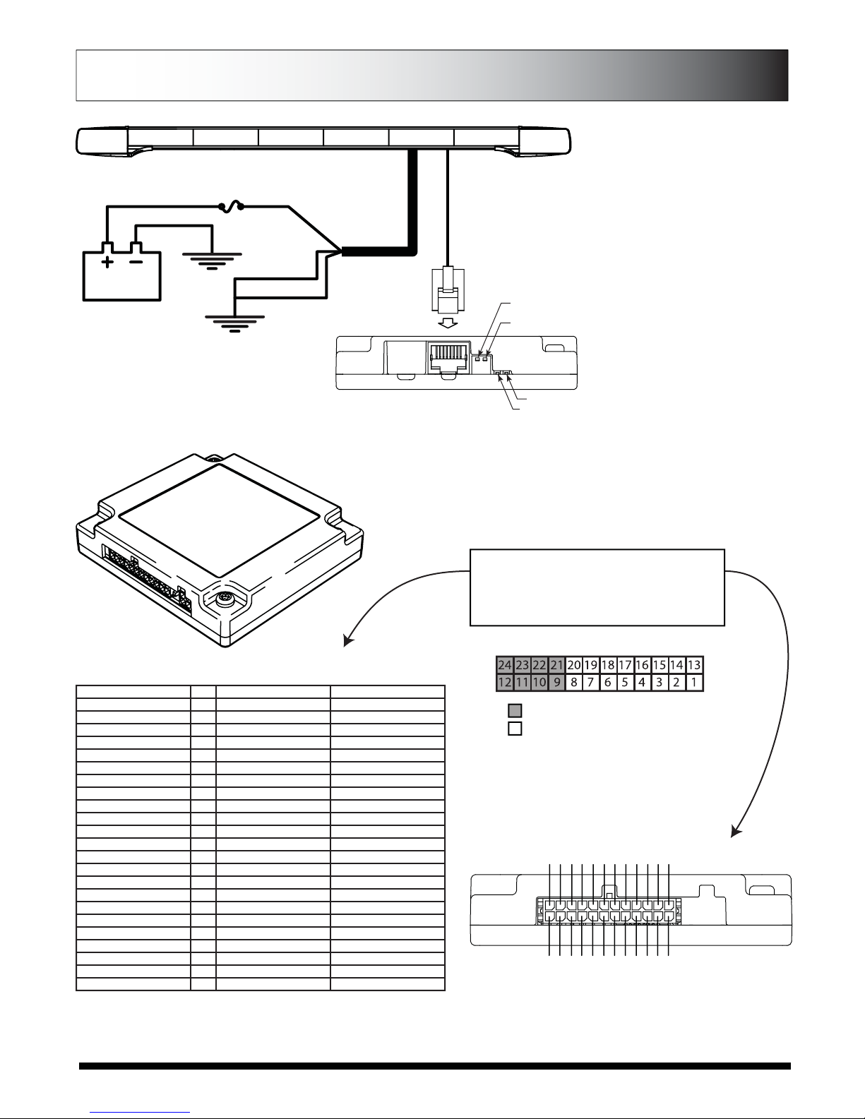
PIN#24 - Light Green/White
PIN#23 - Red Black
PIN#22 - Orange/White
PIN#21 - Yellow/White
PIN#20 - Brown
PIN#19 - Red/White
PIN#18 - Pink
PIN#17 - Red
PIN#16 - Orange
PIN#15 - Yellow
PIN#14 - Green
PIN#13 - Blue
Pink/White - PIN#12
Purple/White - PIN#11
Gray/White - PIN#10
Black/White - PIN#09
White - PIN#08
Purple - PIN#07
Brown/White - PIN#06
Light Green - PIN#05
Black - PIN#04
Gray - PIN#03
GreenWhite - PIN#02
Blue/White - PIN#01
Light Green/White 24 Left Turn Signal* Discrete Output #4*
Red/Black 23 Right Turn Signal* Discrete Output #3*
Orange/White 22 Rear Inboard 3 Discrete Output #2*
Yellow White 21 Rear Inboard 2 Discrete Output #1 (L)*
Brown 20 Front Takedown Front Takedown
Red/White 19 Alley Flash Alley Flash
Pink 18 Alley Driver Alley Driver
Red 17 Alley Passenger Alley Passenger
Orange 16 Front Inboard 3 Front Inboard 3
Yellow 15 Front Inboard 2 Front Inboard 2
Green 14 Front Inboard 1 Front Inboard 1
Blue 13 Front Corners Front Corners
Pink/White 12 Arrow, Left* Discrete Output #8 (R)*
Purple/White 11 Arrow, Center* Discrete Output #7*
Gray/White 10 Arrow, Right* Discrete Output #6*
Black/White 9 Arrow,Warning Discrete Output #5*
White 8 Pattern Select* Pattern Select*
Purple 7 Low Power Low Power
Brown/White 6 Front Takedown Flash Front Takedown Flash
Light Green 5 Auxiliary* Auxiliary*
Black 4 Cruise Lights* Cruise Lights*
Gray 3 Mode Select* Mode Select*
Green/White 2 Rear Inboard 1 Rear Inboard 1
Blue/White 1 Rear Corners Rear Corners
Wire Color
(Major Color/Stripe) Pin#
Discrete Functions
(8 Wire Arrow Control)
Standard Functions
(4 Wire Arrow Control)
* - Reference page 11 for detailed explanation of functions
Note - Reference Switch table for explanation of what inputs are affected by
Active Low Switches
Functional Inputs
Fuctional inputs connect to your control head or
switching unit. Applying +12Vdc to any functional
input will activate it’s function (default-active high).
For more information, see switches explanantion on
second page.
Connector Pinning Chart
Controlled by Active Low Switch #2
Controlled by Active Low Switch #1
· When the switch is in the up position inputs connected to that switch are
active high. To activate an active high input, apply 12Vdc.
· When the switch is in the down position inputs connected to that switch
are active low. To activate the active low, apply ground (negative).
BREAKOUT BOX
DRAIN WIRE
BLACK 12 GA.
GROUND
40Amp FUSE
(Customer Supplied)
GROUND
POWER
CABLE
RED 12 GA.
RJ-45 CABLE
Active Low
Switch #1
Active Low
Switch #2
Red LED
Green LED
RED LIGHT
No Inputs Flashes Every 5 Secs.
Input Activated Steady On
Added Input Brief Flash
GREEN LIGHT
Command Rec’d Steady On Has good
(See below) connection
LOW POWER (STANDBY) MODE
If there is no input to the breakout box for
15 seconds, the lightbar will go into a
“standby” mode. The standby mode is a
low power mode that is used to extend
the life of your battery. The green light
will turn off when the lightbar enters
standby mode. The red light will flash
every five seconds showing that it has
power. The lightbar will awaken from the
standby mode if any input is activated on
the breakout box.
*note in standby mode each switch in the
down position will contribute to another
0.03A of standby current.
Page 12
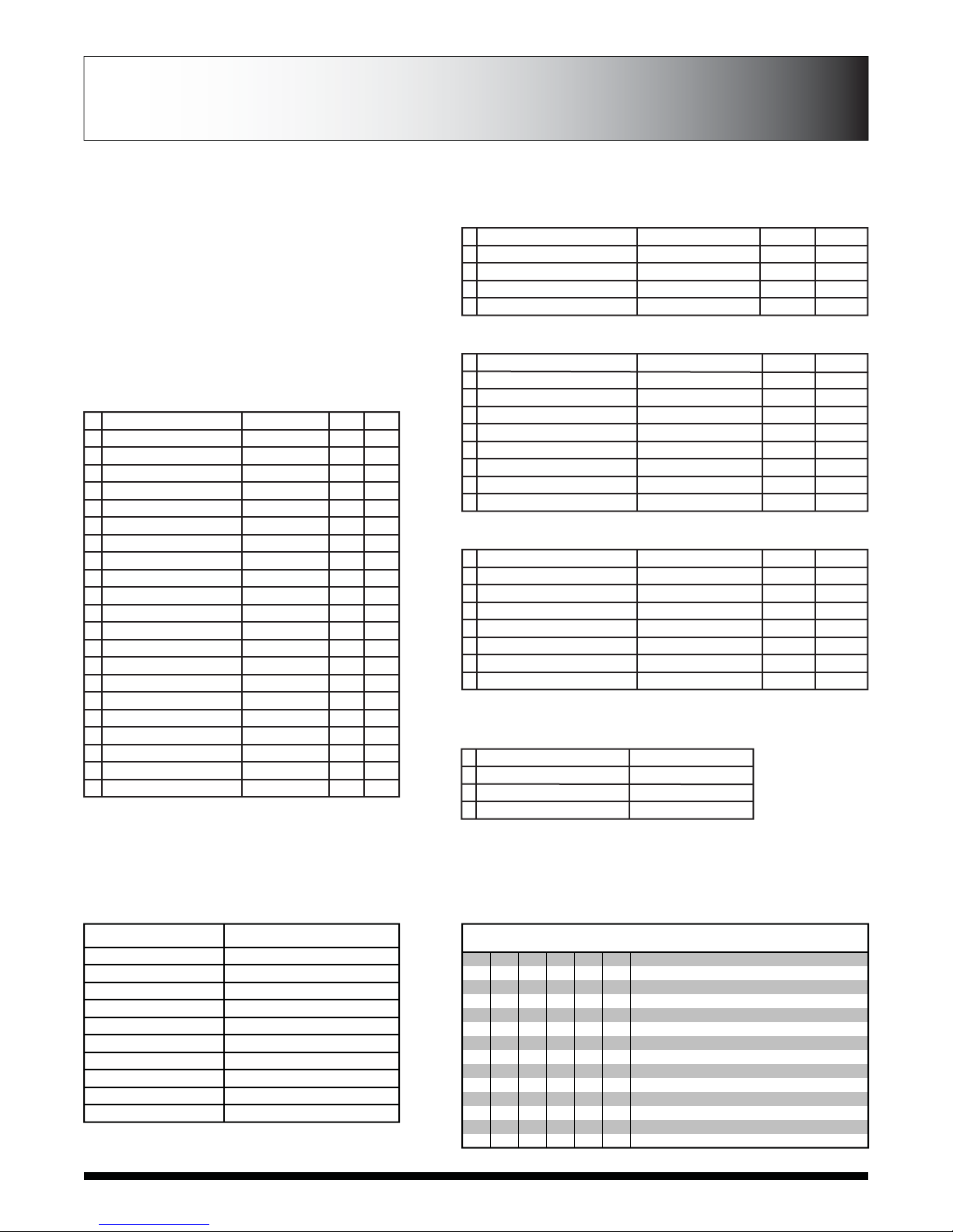
FLASH PATTERN TABLE
BREAKOUT BOX HOOKUP:
Make sure the 24-pin connector and the RJ-45
connector are snapped in securely.
Follow the label for the wire color to connect to a
12Vdc source, which turns on that given light or
lights.
Make sure your wire connections are secured and
isolated from any other wire.
1
2
3
4
Solid Arrow Plus, Slow
Solid Arrow, Slow
Individual Arrow, Fast
Chaser Arrow, Fast
Grow / Decay
Solid
Individual
2X Individual
Directional Bar Directional Function Patterns For
Left, Center Out, & Right Sequences
1
2
3
4
5
RoadRunner™
PowerPulse™
Q-Switch™
ETM™
Steady Burn
Alternating
Alternating
Variable
Simultaneous
Steady Burn
115
180
-
214
-
1.92
3.00
-
3.57
-
LED Takedown & Alley Flash Patterns
1
2
3
4
5
6
7
8
9
PowerPulse™ Alternating
PowerPulse™ Alternating
Quad Alternating
Warp Alternating
Hyper Scan
Super Scan
Power Flash
Thunder and Lightning
Center Out
Left/Right
Center Out
Adjacent
2X Individual Sweep
Pulsing + Sweep
Dual Rate Pulse/Alt
Dual Rate Alt/Pulse
Random
180
180
80
350
-
-
-
-
-
3.00
3.00
1.35
5.88
-
-
-
-
-
Directional Bar Warning Function Patterns
10
11
12
13
14
15
16
17
RoadRunner™
Warp
Warp
Inter-Cycle Flash
Inter-Cycle Flash
Inter-Cycle Flash
Inter-Cycle Flash
Inter-Cycle Flash
Alternating
Adjacent
Adjacent
Adjacent
Alternating
Alternating
Alternating
Alternating
115
350
350
-
-
-
-
-
1.92
5.88
5.88
-
-
-
-
-
Split Arrow Bars Also Have The Following Multi-color Patterns
LED Module Flash Patterns
#
1
2
3
4
5
6
7
8
9
10
11
12
13
14
15
16
17
18
19
20
21
Pattern Name
Quint
Warp
Inter-Cycle Flash
Quad Flash
RoadRunner™
RoadRunner™
Slow Runner
Slow Runner
Q-Switch™
Single, Steady Burn
Quad, Steady Burn
Warp, Steady Burn
Nothing, Steady Burn
E-Pattern Single Flash
E-Pattern Double Flash
E-Pattern Single Flash
E-Pattern Double Flash
Warp 1,2,3
Warp 2,3,1
Warp 3,2,1
Steady Burn
Sequence
Alternating
Alternating
Alternating
Alternating
Alternating
Simultaneous
Alternating
Simultaneous
Variable
Steady Burn
Steady Burn
Steady Burn
Steady Burn
Alternating
Alternating
Simultaneous
Simultaneous
Variable
Variable
Variable
Steady Burn
fpm*
70
350
-
80
115
115
70
70
-
115
80
350
-
230
128
230
155
-
-
-
-
fps**
1.18
5.88
-
1.35
1.92
1.92
1.16
1.16
-
1.92
1.35
5.88
-
3.85
2.13
3.85
2.6
-
-
-
-
*fpm=Flashes per Minute
**fps=Flashes per Second
FLASH PATTERNS AND CONNECTOR
INSTRUCTIONS
LIGHTBAR CONTROLLER CONNECTOR INSTRUCTIONS
Light Output Groups
Orange
Brown
Red and Yellow
Green
Blue
Red and Yellow (2-wire)
Green (2-wire)
Blue (2-wire)
White
Small Connector
Input Group Control
Front Corners
Rear Corners
Front Inboard 1
Front Inboard 2
Front Inboard 3
Rear Inboard 1
Rear Inboard 2
Rear Inboard 3
Front Takedown Flash
Alley Flash
PURPOSE
8-WIRE CONTROL
NO ARROW
N/A
4 MOD ARROW
5 MOD ARROW
6 MOD ARROW
7 MOD ARROW
8 MOD ARROW
PASSENGER-SIDE EXIT
DRIVER-SIDE EXIT
SPLIT-COLOR ARROW MODULES
FULL ARROW MODULE
FOR TURN SIGNALS ON YELLOW OUTPUT
FOR TURN SIGNALS ON BLUE OUTPUT
EPL 9000 SWITCH SETTINGS
SW1
Off
Off
Off
Off
On
On
On
On
SW2
Off
Off
On
On
Off
Off
On
On
SW3
Off
On
Off
On
Off
On
Off
On
SW4
On
Off
SW5
On
Off
SW6
On
Off
Page 13

LIGHT MODULE WIRE HARNESS LOCATIONS
CONTROLLER AND WIRE HARNESS INSTRUCTIONS
Colors shown indicate color coded labels on
wiring harness.
White is used for all Take Down lights. Replace
color indicated on diagram with white labeled
wire.
SM=Small connector used on Alley lights only.
If modules are being replaced in the field make
sure they are reinstalled with single wire
connectors to FRONT of vehicle. See below.
Green
Single Wire
Red, Blue Double
Wire (Rear)
REPLACEMENT OF INBOARD, CORNER, TAKEDOWN AND ALLEY LED MODULES:
1. Disconnect main power.
2. Remove top cover by removing 6 sealed torx head screws.
3. Locate module and remove mounting screw. Pull module from lightbar.
4. Remove connector from rear of module by disengaging locking latch and pull
connector from back of module. (see illustration at right)
5. Push module connector into module ensuring locking latch is seated properly.
6. Replace module and 2 screws that fasten module to base extrusion.
7. Restore power to bar and test new module to ensure functionality.
8. Replace top cover of bar with screws removed in step 2.
DRIVER
SIDE
PASSENGER
SIDE
FRONT
36” BAR
C
D
A
E
B
E
11 12 13 14
31 32 33 34
ORANGE
SM
BROWN
GREEN RED RED GREEN ORANGE
SM
BROWN
GREEN RED RED GREEN
42” BAR
C
D
A
E
B
E
11 12 13 14 15
31 32 33 34 35
ORANGE
SM
BROWN
BLUE GREEN RED GREEN BLUE ORANGE
SM
BROWN
BLUE GREEN RED GREEN BLUE
48” BAR
C
D
A
E
B
E
11 12 13 14 15 16
31 32 33 34 35 36
ORANGE
SM
BROWN
ORANGE
SM
BROWN
BLUE GREEN RED RED GREEN
BLUE GREEN RED RED GREEN
BLUE
BLUE
54” BAR
C
D
A
E
B
E
11 12 13 14 15 16 17
31 32 33 34 35 36 37
YELLOW
ORANGE
SM
BROWN
ORANGE
SM
BROWN
BLUE GREEN RED GREEN BLUE
BLUE GREEN RED GREEN BLUE
YELLOW
YELLOW
YELLOW
60” BAR
C
D
A
E
B
E
11 12 13 14 15 16 17 18
31 32 33 34 35 36 37 38
ORANGE
SM
BROWN
ORANGE
SM
BROWN
BLUE GREEN RED RED GREEN
BLUE GREEN RED RED GREEN
BLUE
BLUE
YELLOW
YELLOW
YELLOW
YELLOW
72” BAR
C
D
A
E
B
E
ORANGE
SM
BROWN
ORANGE
SM
BROWN
BLUE GREEN RED* RED* GREEN
BLUE BLANK RED* RED* BLANK
BLUE
BLUE
YELLOW
YELLOW
YELLOW
YELLOW
31 32 33 34 35 36 37 38 39 40
11 12 13 14 15 16 17 18 19 20
RED* RED*
RED* RED*
* DENOTES
DOUBLE WIRE
UNITS IN FRONT
ON 72” BAR
ONLY!
Page 14

PINNACLE TROUBLESHOOTING
NORMAL OPERATION
Under Normal operation with lightbar turned on the breakout box will have the Green and Red LED light on steady. When ever you change
an input to the lightbar the Red LED on the breakout box will flash then go back to steady.
When the lightbar is off (no inputs active) the Green LED on the breakout box will stay on for 15 seconds then go off putting the lightbar into
sleep (standby) mode. The Red LED will flash every 5 seconds to tell you there is power to the breakout box and it is waiting for an input to
turn on the lightbar.
NO OPERATION
No LED on or flashing on Breakout box; Check input power and ground to lightbar, check data cable for damage and/or
opens, check 5 amp fuse in electronic control box in lightbar.
Breakout box LED’s operating correctly; Check FH1 & FH2 fuse in electronic control box in lightbar
NO OR INCORRECT INBOARDS OR CORNERS LIGHTS (WARNING)
Breakout box LED’s operating correctly; Check FH1 fuse in electronic control box in lightbar
No steady Red LED on breakout box; Check 24-pin connector at breakout box (insure it is snapped in correctly), check
appropriate input to breakout box for output lights which should be on
No rear warning lights; Check dip switch SW5 setting for full (off) or split (on) arrow (on full you may not
get any warning) (after arrow dip switch changes main power must be cycled)
NO TAKEDOWNS OR ALLEYS LIGHTS
Breakout box LED’s operating correctly; Check FH2 fuse in electronic control box in lightbar
No steady Red LED on breakout box; Check 24-pin connector at breakout box (insure it is snapped in correctly), check
appropriate input to breakout box for output lights which should be on
INCORRECT OR NO ARROW OPERATION
Breakout box LED’s operating correctly; Check dip switches setting in electronic control box in lightbar (after arrow dip
switch changes main power must be cycled)
No steady Red LED on breakout box; Check 24-pin connector at breakout box (insure it is snapped in correctly), check
appropriate input to breakout box for output lights which should be on
Arrow direction incorrect; Change passenger/drivers side dip switch SW4 in electronic control box in lightbar
(after arrow dip switch changes main power must be cycled)
8-wire control not operating; Check dip switch setting SW1-3 (should be off, off, off) in electronic control box in
lightbar (after arrow dip switch changes main power must be cycled)
Split arrow not operating; Check dip switch SW5 (should be on) in electronic control box in lightbar (after
arrow dip switch changes main power must be cycled)
Page 15
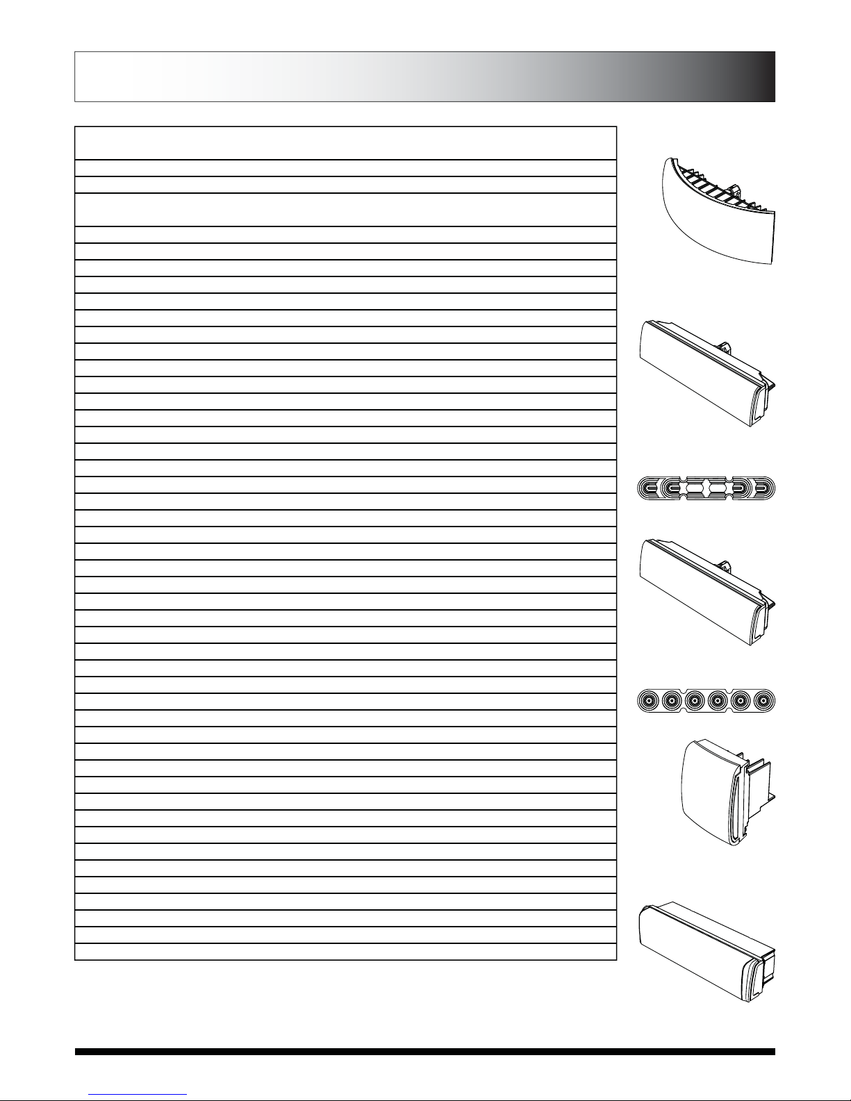
REPLACEMENT PARTS
Inboard LED Assembly
Alley Light Assembly
Takedown/Worklight/
Assembly
Corner LED Assembly
Pre-empt Module
EPL PART # DESCRIPTION
PEPL9A0C Pinnacle Blank Alley Light - Clear Lens/No LEDs
PEPL9A1C-D Pinnacle Alley Light, 15° Forward Facing, Driver Side - Clear Lens/White LEDs
PEPL9A1C-P Pinnacle Alley Light, 15° Forward Facing, Passenger Side - Clear Lens/White LEDs
PEPL9A2C Pinnacle Alley Light, Standard - Clear Lens/White LEDs
PEPL9BBHNS Pinnacle Breakout Box Harness, 12" Length
PEPL9BBHNL Pinnacle Breakout Box Harness, 36" Length
PEPL9CNTRL1 Pinnacle Motherboard, 12 volt
PEPL9CS12AA Pinnacle Corner Module - Amber Lens/Amber LEDs
PEPL9CS12AC Pinnacle Corner Module - Clear Lens/Amber LEDs
PEPL9CS12BB Pinnacle Corner Module - Blue Lens/Blue LEDs
PEPL9CS12BC Pinnacle Corner Module - Clear Lens/Blue LEDs
PEPL9CS12GC Pinnacle Corner Module - Clear Lens/Green LEDs
PEPL9CS12RC Pinnacle Corner Module - Clear Lens/Red LEDs
PEPL9CS12RR Pinnacle Corner Module - Red Lens/Red LEDs
PEPL9CS12WC Pinnacle Corner Module - Clear Lens/White LEDs
PEPL9HL6C Pinnacle Takedown/Work Light Module - Clear Lens/White LEDs
PEPL9L00A Pinnacle Blank Inboard Module - Amber Lens/ No LEDs
PEPL9L00B Pinnacle Blank Inboard Module - Blue Lens/ No LEDs
PEPL9L00C Pinnacle Blank Inboard Module - Clear Lens/ No LEDs
PEPL9L00R Pinnacle Blank Inboard Module - Red Lens/ No LEDs
PEPL9LLSAA Pinnacle Inboard Module - Amber Lens/Amber LEDs
PEPL9LLSAC Pinnacle Inboard Module - Clear Lens/Amber LEDs
PEPL9LLSBB Pinnacle Inboard Module - Blue Lens/Blue LEDs
PEPL9LLSBC Pinnacle Inboard Module - Clear Lens/Blue LEDs
PEPL9LLSGC Pinnacle Inboard Module - Clear Lens/Green LEDs
PEPL9LLSRC Pinnacle Inboard Module - Clear Lens/Red LEDs
PEPL9LLSRR Pinnacle Inboard Module - Red Lens/Red LEDs
PEPL9LLSWC Pinnacle Inboard Module - Clear Lens/White LEDs
PEPL9LLSFC Pinnacle Dual Color Arrow Module, Clear Lens – White/Amber
PEPL9LLSKC Pinnacle Dual Color Arrow Module, Clear Lens – Red/Amber
PEPL9LLSMC Pinnacle Dual Color Arrow Module, Clear Lens – Blue/Amber
PEPL9LLSPC Pinnacle Dual Color Arrow Module, Clear Lens – Green/Amber
PEPL9LLSZC Pinnacle Dual Color Arrow Module, Clear Lens – No LEDs/Amber
PEPL9LLSJC Pinnacle Dual Color Warning Module Clear Lens - Red/Blue
PEPL9LLSNC Pinnacle Dual Color Warning Module Clear Lens - Blue/Green
PEPL9RFGR Roof Wire Grommet for External Break Out Box on Pinnacle Lightbars
PETLJ00 External Breakout Box for ETL 5000 & Pinnacle Lightbars
PETLK00 Adjustable Height Mounting Bracket (1 bracket) for use w/ ETL 5000 & Pinnacle Lightbars
PETLK04 Low Profile Fixed Height Mounting Bracket (1 bracket) for use w/ ETL 5000 & Pinnacle Lightbars
PETLMX1 Hook Kit Extension for use w/ Adjustable Height Bracket on ETL 5000 & Pinnacle Lightbars
PETLM00 Permanent Mount Hardware for the Adjustable Height Bracket for use w/ ETL 5000 & Pinnacle Lightbars
PETLM(nn) Adjustable Height Bracket Hook Kit for ETL 5000 or Pinnacle Lightbars:*
PETLR00
Permanent Mount Hardware for the Low Profile Fixed Height Bracket for use w/ ETL 5000 & Pinnacle Lightbars
PEPL9GTT1C Pre-empt Module
PEPL9RFGR2 Roof Grommet
PEPL9GTTHN Harness
PEPL9LLH12(x)C Pinnacle High Diode Dual Color Rear Arrow Module
* SEE "HOOK KIT COMPATIBILITY CHART" FOR VEHICLE MODEL COMPATIBILITY
http://www.soundoffsignal.com/warnamber/lightbars/literature/HookKits_ETL5000.pdf
STANDARD REPLACEMENT PARTS
Page 16

CLEANING -
Keeping the lenses clean and scratch free will optimize the performance of the lightbar. To clean use a soft
cotton cloth and mild soapy water to clean dirt and insects off from the lenses. Never use window
cleaners or harsh chemicals on the lenses; this may cause failure of the lenses or reduce clarity resulting
in the reduction of light output.
The exterior of the lightbar also should be cleaned with mild soapy water and a soft cotton cloth.
MOUNTING INTEGRITY:
A review of bolt/hardware/mounting bracket integrity should be performed at the
beginning and end of each shift.
PRODUCT MAINTENANCE
NOTES
Page 17

WARRANTY & RETURN GOODS PROCEDURE
To review our Limited Warranty Statement & Return Policy for this or any SoundOff Signal product please visit our website at
www.soundoffsignal.com and select the “Warranty & Returns” link along the left column of our home page. If you have questions regarding this
product please contact Technical Services, Monday - Friday, 8 am to 5 pm at 1.800.338.7337, press #4 to skip the automated message. Questions
or comments that do not require immediate attention may be emailed to [email protected]. 1.800.338.7337. /
www.soundoffsignal.com / Thank you for trusting us with your safety!
Warranty Return Process
Please contact your SoundOff Signal Sales Representative, Customer Services staff or our Technical Department (800.338.7337) for a RMA#
(Return Merchandise Authorization) number.
The following information is required for issuance of the RMA#:
• Reason for returning the product*
• Address where replacement product is to be shipped*
• Telephone number where you may be reached*
• SoundOff Signal invoice number on which product was purchased**
• SoundOff Signal part number and serial number**
• E-mail address where RMA# should be e-mailed**
• Fax number where RMA# should be faxed**
SoundOff Signal will NOT accept returns without an RMA#. Each RMA# is good for only one (1) item and will expire (7) days after the date it
was issued. Products must be shipped back to SoundOff Signal and the RMA# clearly marked on the outside of the package near the shipping
label. Please use the following address on your shipping label:
ATTN.: RMA#
SoundOff Signal
3900 Central Parkway
Hudsonville, MI 49426
Please see reverse side for manufacturer warranty.
Warranty Exclusions
Shipping & Handling, labor and service fees are non-refundable. SoundOff Signal is not liable for any damage due to installation or personal injury as
a result of using SoundOff Signal product.
Warranty Forfeiture
Warranty will not be granted if the Warranty Return Policy & Procedure rules are not strictly followed. Physical damage resulting from customer
abuse will void warranty. Warranty will also be voided if any SoundOff Signal and/or manufacturer serial tags, product stickers, seals, or the like,
are removed, altered or tampered with. Returned product that is damaged by shipping via the RMA# procedure is not the responsibility of
SoundOff Signal.
* RMA# will not be given without this information.
** If available, please provide this information.
Document effective date on cover and below supersedes previously dated policies and statements.
There are no other warranties, expressed or implied, including, but not limited to, any implied merchantability or fitness for a particular use.
SoundOff Signal reserves the right to modify this warranty statement at any time; or to discontinue, modify, or upgrade any products of its
manufacture with design improvements without prior notice.
ISO-9001 Registered ©2009 SoundOff Signal Emergency Technology Inc. dba SoundOff Signal
Printed in the USA / All Rights Reserved / Specifications subject to change without notice.
PO Box 206 / 3900 Central Parkway / Hudsonville, MI 49426
toll free 800.338.7337 / office 616.896.7100 / order fax 616.896.1286 / www.soundoffsignal.com
EPL9000 9.10
Table of contents
Other Soundoff Signal Dj Equipment manuals

Popular Dj Equipment manuals by other brands


Chauvet Professional
Chauvet Professional Maverick Storm 1 Wash user manual

Guangzhou Yingfeng Lighting Equipment
Guangzhou Yingfeng Lighting Equipment MHY10803 user manual

PSL
PSL RAINSTAGE LED 24/10 instructions

Strand
Strand Fresnelite 12081 operating instructions

Spirit Halloween
Spirit Halloween Mr. Salty Installation and operating instructions

Flash professional
Flash professional P7100457 user manual


