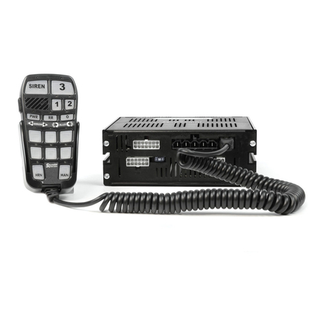
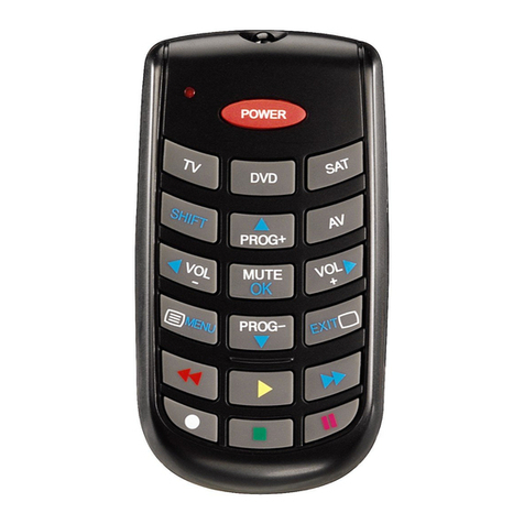
Soundoff Signal nERGY bluePRINT ENGCP15001 Owner's manual

1.800.338.7337 / www.soundoffsignal.com
HANDHELD REMOTE
ENGCP15001
PROGRAMMING MANUAL
EVCS_HANDHELD_ENGCP15001 05.16
NOTICE:
Installers and users must comply with all applicable federal, state and local laws regarding use and installation of warning devices.
Improper use or installation may void warranty coverage. To review our Limited Warranty Statement & Return Policy for this or any SoundOff Signal product, visit our website at
www.soundoffsignal.com/sales-support. If you have questions regarding this product, contact Technical Services, Monday - Friday, 8 a.m. to 5 p.m. at 1.800338.7337 (press #4 to skip the
automated message). Questions or comments that do not require immediate attention may be emailed to [email protected].
SUPERIOR CUSTOMER RELATIONSHIPS. SMARTLY DESIGNED LIGHTING & ELECTRONIC SOLUTIONS.
.
Tech Specs
nERGY Control System
Control Panel
Input Voltage: 10-16Vdc (Negative Ground)
Sleep Current: 8 mA
Inputs: 1x 3pin MIC Input
Reverse Polarity Protection: Protected
Transient Protection: Protected
High Voltage Protection: Protected
Low Voltage Protection: Protected
Operating Temp: -40˚C to + 65˚C
Dimensions: 6.9”H x 3.5”Wx 1.2”D
Weight, Boxed: 1.3lb.
Weight, Device Only: 1.1lb
The control panel is not waterproof. Install in a protected location away from excessive
heat and moisture.
* SIREN AUDIO BUTTON ACTIVATED
(EXCEPT RADIO REBROADCAST)
STANDBY SPKR 1 INDICATOR SPKR 2 INDICATOR CONDITION
FLASHING ON ON OVER-TEMPERATURE, (380R ONLY)
FLASHING OFF ON UNDER-VOLTAGE
FLASHING ON OFF OVER-VOLTAGE
FLASHING FLASHING - COMM FAULT - RELAY
FLASHING - FLASHING COMM FAULT - AMP
FLASHING FLASHING FLASHING COMM FAULT -CENTRAL CONTROLLER
ON - - STANDBY MODE
*OFF ON - SPKR 1 IS ACTIVE
*OFF - ON SPKR 2 IS ACTIVE
*OFF OFF - SPKR 1 IS NON-FUNCTIONING
*OFF - OFF SPKR 2 IS NON-FUNCTIONING
SIREN AMPLIFIER DIAGNOSTIC INDICATORS:
•HIGH CURRENT interconnects must be properly terminated. Poor crimp quality can
cause heat build-up and re. Follow crimp connector manufacturer instructions.
•DO NOT install this product or route any wires in the Air Bag Deployment Zone. Refer
to vehicle Owner’s Manual for deployment zones.
•Do NOT use system to disconnect headlights, brake lights or other safety equipment.
•Unit may become hot to touch during normal operation.
•Failure to properly install connectors, fuses or wiring may cause vehicle failure or re.
•Installation must only be performed by trained technician. Installer must determine
vehicle wiring conguration and proper integration of system.
•Use proper wire gauge. All power wires connecting to positive (+) or negative (-)
battery terminal or local chassis ground (-) must be sized to supply at least 125% of
max. current and properly fused at power source.
•Install protective grommets when routing wire through rewall or metal.
WARNING
1

1.800.338.7337 / www.soundoffsignal.com
HANDHELD REMOTE
ENGCP15001
PROGRAMMING MANUAL
EVCS_HANDHELD_ENGCP15001 05.16
NOTICE:
Installers and users must comply with all applicable federal, state and local laws regarding use and installation of warning devices.
Improper use or installation may void warranty coverage. To review our Limited Warranty Statement & Return Policy for this or any SoundOff Signal product, visit our website at
www.soundoffsignal.com/sales-support. If you have questions regarding this product, contact Technical Services, Monday - Friday, 8 a.m. to 5 p.m. at 1.800338.7337 (press #4 to skip the
automated message). Questions or comments that do not require immediate attention may be emailed to [email protected].
SUPERIOR CUSTOMER RELATIONSHIPS. SMARTLY DESIGNED LIGHTING & ELECTRONIC SOLUTIONS.
Slide Switch Mode:
1. Press and Hold Auxiliary Button #1 and #4 until Level 2 LED
ashes.
2. Press Auxiliary switch 1, 2, or 3 depending on required mode of
operation.
Aux 1: Progressive 1,2,3
Level 1 selected: Active Outputs: 1
Level 2 selected: Active Outputs: 1,2
Level 3 selected: Active Outputs: 1,2,3
Aux: 2 Progressive 1,2,3 with option to turn off lower levels
Level 1 selected: Active Outputs: 1
Level 2 selected: Active Outputs: 1,2 (Level 1 may be turned OFF)
Level 3 selected: Active Outputs: 1,2,3 (Level 1 and 2 may be
turned OFF)
Aux 3: Individual 1,2,3
Level 1 selected: Active Outputs: 1
Level 2 selected: Active Outputs: 2
Level 3 selected: Active Outputs: 3
Toggle ON/OFF
Momentary ON
8 Second Delay
Left Arrow
Right Arrow
Center Out - Arrow
Alley Left
Alley Right
Single Button Arrow
Single Button Alley
4. Press and release Auxiliary Button until desired mode is
selected.
5. Continue steps 2-4 for any other Auxiliary Buttons needing to
be programmed.
LEGEND:
ON =
Denotes Factory Default Setting
NOTE:
For All programming modes: Momentarily depress Radio
Rebroadcast push-button to save and exit.
To hear samples of all the tones available go to
www.soundoffsignal.com website.
Programming Modes
Auxiliary Button Programming:
1. Press and Hold Auxiliary Button #1 and #6 until Level 1 LED Flashes.
2. Press the auxiliary button which setting is going to be viewed/
changed.
3. Monitor the Arrow/Alley LED’s to determine setting for Auxiliary
Button
Input Settings:
*1. Press and Hold Auxiliary Button #1 and #3 until LEVEL #3
LED ashes.
1. Park Kill Polarity Mode: Determines what voltage level will
activate park kill functions. Disables AUX Input
ON = Activated when Ground is applied to Park
Kill input wire.
OFF = Activate when +V is applied to Park Kill
input wire
*2. Horn Ring Polarity Mode: Determines what voltage level will
activate Horn Ring functions.
ON = Activated when Ground is applied to Horn
Ring input wire.
OFF = Activated when +V is applied to Horn
Ring input wire.
*3. PA Volume Control (see Setting PA Volume)
ON = RR Button Adjustable
OFF = Programmed
4. Level 3 Tone Activation : Determines when the siren tone
push-buttons on control panel are enabled.
ON = Tone push buttons always enabled
OFF = Tone push button only enabled with slide
switch is in position #3.
5. 8 Second Buzzer alert: Provides audible beep when
ever any auxiliary switches are ON or level 1, 2 or 3
is active.
ON = Enabled
OFF = Disabled
*= Setting can be selected in software
conguration application
Setting in conguration application will
override control panel displayed setting.
*= Setting can be selected in software conguration
application
Setting in conguration application will override
control panel displayed setting.
2

1.800.338.7337 / www.soundoffsignal.com
HANDHELD REMOTE
ENGCP15001
PROGRAMMING MANUAL
EVCS_HANDHELD_ENGCP15001 05.16
NOTICE:
Installers and users must comply with all applicable federal, state and local laws regarding use and installation of warning devices.
Improper use or installation may void warranty coverage. To review our Limited Warranty Statement & Return Policy for this or any SoundOff Signal product, visit our website at
www.soundoffsignal.com/sales-support. If you have questions regarding this product, contact Technical Services, Monday - Friday, 8 a.m. to 5 p.m. at 1.800338.7337 (press #4 to skip the
automated message). Questions or comments that do not require immediate attention may be emailed to [email protected].
SUPERIOR CUSTOMER RELATIONSHIPS. SMARTLY DESIGNED LIGHTING & ELECTRONIC SOLUTIONS.
ALTERNATE HORN RING CONTROL
OPTION 1 OPTION 2
STANDBY OEM HORN OEM HORN
LEVEL 1 OEM HORN OEM HORN
LEVEL 2 Air Horn or Wail Button
Tone while Pressed *Tap to Turn On Warning Tone, Tap
again to Change Warning Tone. Press
and Hold for Air Horn Tone
LEVEL 3 Tap to turn ON Warning
Tone, Tap again to
change Warning Tone.
Press and Hold for Air
Horn Tone
TONE SWITCH
OFF:
Air Horn Tone or
Wail Button Tone
while Pressed *
TONE SWITCH
ON:
Tap to change
Warning Tone,
Press and Hold
for Air Horn Tone
Horn Ring Program:
1. Press and Hold Auxiliary Button #3 and #4 until ‘Ø’ LED
ashes.
1. Alternate Horn Ring Control: Custom operation of vehicle
horn when pressed. Refer to gure left for details.
ON = Enabled
OFF = Disabled
Other Modes:
1. Press and Hold Auxiliary Button #1 and #5 until LEVEL #1 and
LEVEL #3 indicator LED ashes.
1. Buzzer: Audible tone from control panel whenever operator
presses push-button or changes position of slide/rotary
switch.
ON = Enabled
OFF = Disabled
*2. Park Kill Latch: When Park Kill input is triggered, determines
how siren tone proceeds once park kill input is no longer
active.
ON = Tone remains disabled until operator
selects other tone.
OFF = Tone resumes once Park Kill input is
no longer active
* Set in “Horn Ring Program”
3. Horn Ring Standby Tone
2. Alternate Horn Ring Control Option:
(Alternate Horn Ring Control must be enabled).
Custom operation of vehicle horn when pressed.
Refer to gure left for details.
ON = Option 2
OFF = Option 1
2. When nished, momentarily depress Radio Rebroadcast (RR)
button to exit programming mode.
3. Power Down: Determines whether siren will operate when
ignition input has no voltage
ON = Siren will operate w/o voltage on
ignition input
OFF = Siren is disabled when no voltage is
present on ignition input
4. Auxiliary Input: Determines which siren tone will activate when
auxiliary input is activated.
ON = Air Horn tone
OFF = Tone which is programmed on Wail
push-button
MASTER
ON / OFF
(Siren Standby)
Control
LEDs
AUXILLARY
BUTTON #s
1 2 3
4 5 6
LEVEL Switches (1,2,3
with indicators)
HORN LED
MANUAL
LED
‘Ø’ LED
SIREN LED
RADIO
REBROADCAST
LED
2
3

1.800.338.7337 / www.soundoffsignal.com
HANDHELD REMOTE
ENGCP15001
PROGRAMMING MANUAL
EVCS_HANDHELD_ENGCP15001 05.16
NOTICE:
Installers and users must comply with all applicable federal, state and local laws regarding use and installation of warning devices.
Improper use or installation may void warranty coverage. To review our Limited Warranty Statement & Return Policy for this or any SoundOff Signal product, visit our website at
www.soundoffsignal.com/sales-support. If you have questions regarding this product, contact Technical Services, Monday - Friday, 8 a.m. to 5 p.m. at 1.800338.7337 (press #4 to skip the
automated message). Questions or comments that do not require immediate attention may be emailed to [email protected].
SUPERIOR CUSTOMER RELATIONSHIPS. SMARTLY DESIGNED LIGHTING & ELECTRONIC SOLUTIONS.
4
POWER LED SIREN LED HORN LED MANUAL LED CONDITION
ON FLASHING ON ON OVER-TEMPERATURE (380R ONLY)
ON FLASHING OFF ON UNDER-VOLTAGE
ON FLASHING ON OFF OVER-VOLTAGE
ON FLASHING FLASHING - COMM FAULT - RELAY
ON FLASHING - FLASHING COMM FAULT - AMP
ON FLASHING FLASHING FLASHING COMM FAULT -RELAY AND AMP
ON OFF - - STANDBY MODE
OFF ON ON - SPKR 1 IS ACTIVE
OFF ON OFF - SPKR 1 IS NOT-FUNCTIONING
OFF ON - ON SPKR 2 IS ACTIVE
OFF ON - OFF SPKR 2 IS NOT-FUNCTIONING
SIREN AMPLIFIER DIAGNOSTIC
INDICATORS:
LED INDICATOR CONDITION
OFF RELAY OUTPUT IS OFF
ON RELAY OUTPUT IS ON
FLASHING RELAY OUTPUT HAS A FAULT
AUXILILARY AND LEVEL SWITCH LED
INDICATORS:
AUX
BUTTON #4 AUX
BUTTON #5 AUX
BUTTON #6 PRIMARY
SPKR 1 TONE
SECONDARY
SPKR 2 TONE
OFF OFF OFF Disabled Disabled
OFF OFF ON WAIL 1 WAIL 2
OFF ON OFF Yelp 1 Yelp 2
OFF ON ON ALERT A YELP 1
ON OFF OFF Piercer 1 Yelp 1
ON OFF ON HiLo Super HiLo Tone
ON ON OFF Super HiLo Tone Super HiLo Tone
ON ON ON Cycle Tone
(Wail 1, Yelp 1, Alert A, Piercer) Cycle Tone
(Yelp 1, Alert A, Piercer, Yelp 1)
AUXILIARY TONE #1
Tone #1
Setting PA Volume:
1. PA Volume Control (see Input Settings, 1-3)
If set to “Programmed”
2. Press and Hold Auxiliary Button #1 and #2 until LEVEL #2
and LEVEL #3 LED ashes.
a. Depress and hold PA switch on microphone and press
Pushbutton 1-6 depending on volume required. When
correct volume is determined, press Radio Rebroadcast
and the volume setting will be permanently stored.
If set to “RR Button Adjustable”
3. Momentarily press RR Button to select PA Volume. PA Volume
will be displayed on indicators below RR Button.
1-(LOW)
2
3
4
5-(HIGH)
LOW 2
5
4
3
HIGH
*
Tones Program:
1. Press and Hold Buttons #2 and #5 until Level 1, Level 2 and
Level 3 LEDs ash.
2. Press SIREN button to program the tones (each press of the
SIREN button will advance to next TONE mode). Note:
in operation, each press of the SIREN button will scroll
between the 3 programmed tones.
3. SIREN Mode
SIREN LED: Siren Tone #1
PWR LED: Siren Tone #2
SIREN LED and PWR LED: Siren Tone #3
4. Press Auxiliary Buttons to get required tone
5. HORN Button:
Press Horn Button and HORN 1 LED will turn ON
Press Auxiliary Buttons to get required tone.
6. Man Button:
Press MAN Button and MANUAL LED will turn ON
Press Auxiliary Buttons to get required tone.
MANUAL BUTTON TONE DURATION
MOMENTARY: When played solo
LATCHED: When played over other tones.
*

1.800.338.7337 / www.soundoffsignal.com
HANDHELD REMOTE
ENGCP15001
PROGRAMMING MANUAL
EVCS_HANDHELD_ENGCP15001 05.16
NOTICE:
Installers and users must comply with all applicable federal, state and local laws regarding use and installation of warning devices.
Improper use or installation may void warranty coverage. To review our Limited Warranty Statement & Return Policy for this or any SoundOff Signal product, visit our website at
www.soundoffsignal.com/sales-support. If you have questions regarding this product, contact Technical Services, Monday - Friday, 8 a.m. to 5 p.m. at 1.800338.7337 (press #4 to skip the
automated message). Questions or comments that do not require immediate attention may be emailed to [email protected].
SUPERIOR CUSTOMER RELATIONSHIPS. SMARTLY DESIGNED LIGHTING & ELECTRONIC SOLUTIONS.
5
Level Switch Mapping:
1. Press Auxiliary Buttons #4 and #5 until RR LED
Flashes
2. Press Level 1,2, or 3 switch to select level to be
programmed
3. Press Auxiliary Buttons #1-#6 as required. LED
ON = function will turn ON when Level is active
4. Press siren button for desired tone to be
generated for level
Alley Left = Tone 1
Alley right = Tone 2
Alley Left and Right = Tone 3
Setting Backlight/Indicator LED Intensity:
1. Press and Hold Radio Rebroadcast (RR) Button.
2. Then press Aux Buttons 1-6 to select intensity.
1 = Low Intensity
6 = High Intensity
Default - All level #’s produce no tone
AUX
BUTTON #4 AUX
BUTTON #5 AUX
BUTTON #6 PRIMARY
SPKR 1 TONE
SECONDARY
SPKR 2 TONE
OFF OFF OFF Disabled Disabled
OFF OFF ON WAIL 1 WAIL 2
OFF ON OFF Yelp 1 Yelp 1
OFF ON ON ALERT A YELP 1
ON OFF OFF Piercer 1 Yelp 1
ON OFF ON HiLo Super HiLo Tone
ON ON OFF Super HiLo Tone Wail 1
ON ON ON Cycle Tone
(Wail 1, Yelp 1, Alert A, Piercer) Cycle Tone
(Yelp 1, Alert A, Piercer, Yelp 1)
AUXILIARY TONE #1
AUX
BUTTON #4 AUX
BUTTON #5 AUX
BUTTON #6 PRIMARY
SPKR 1 TONE
SECONDARY
SPKR 2 TONE
OFF OFF OFF Disabled Disabled
OFF OFF ON WAIL 1 WAIL 2
OFF ON OFF Yelp 1 Yelp 2
OFF ON ON ALERT A YELP 1
ON OFF OFF Piercer 1 Wail1
ON OFF ON HiLo Wail 1
ON ON OFF Super HiLo Tone Piercer 1
ON ON ON Cycle Tone
(Wail 1, Yelp 1, Alert A, Piercer) Cycle Tone
(Yelp 1, Alert A, Piercer, Yelp 1)
Tone #3
BUTTON
#4 BUTTON
#5 BUTTON
#6 SPKR 1
TONE
SPKR 2
TONE
OFF OFF OFF HORN 1 HORN 1
OFF OFF ON HORN 2 HORN 2
OFF ON OFF HORN 3 HORN 3
OFF ON ON HORN 4 HORN 4
ON OFF OFF HORN 1 HORN 2
ON OFF ON HORN 2 HORN 3
ON ON OFF HORN 3 HORN 4
ON ON ON HORN 4 HORN 2
HORN BUTTON
BUTTON
#4 BUTTON
#5 BUTTON
#6 SPKR 1 TONE SPKR 2 TONE
OFF OFF OFF WAIL 1 (W/FREQ. DECREASE) WAIL 1 (W/FREQ. DECREASE)
OFF OFF ON WAIL 1 (IMMEDIATE OFF) WAIL 1 (IMMEDIATE OFF)
OFF ON OFF YELP 1 YELP 1
OFF ON ON PIERCER PIERCER
ON OFF OFF ALERT A ALERT A
ON OFF ON HiLo HiLo
ON ON OFF SUPER HiLo SUPER HiLo
ON ON ON WAIL 1 (IMMEDIATE OFF) WAIL 1 (IMMEDIATE OFF)
MANUAL BUTTON (SOLO PLAY ONLY)
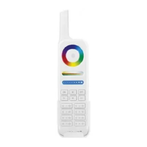
Other Soundoff Signal Remote Control manuals
