© 2015 Rollease Acmeda © 2015 Rollease Acmeda
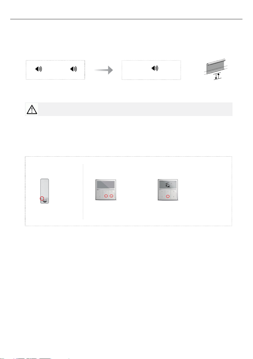
PAIR RF500 SERIES REMOTE TO EL MOTOR
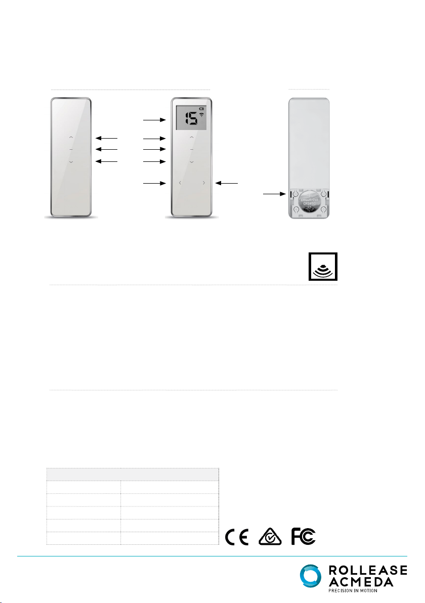
Operation
Item Item Operation Result Illustration
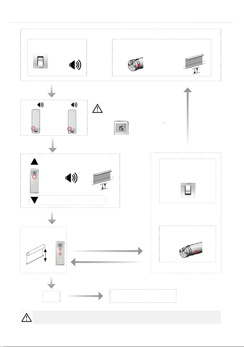
Setup
bottom
limit
1
Keep pressing the
LIMIT key on the
primary transmitter for
6 seconds above
The motor sounds "KA
KA"
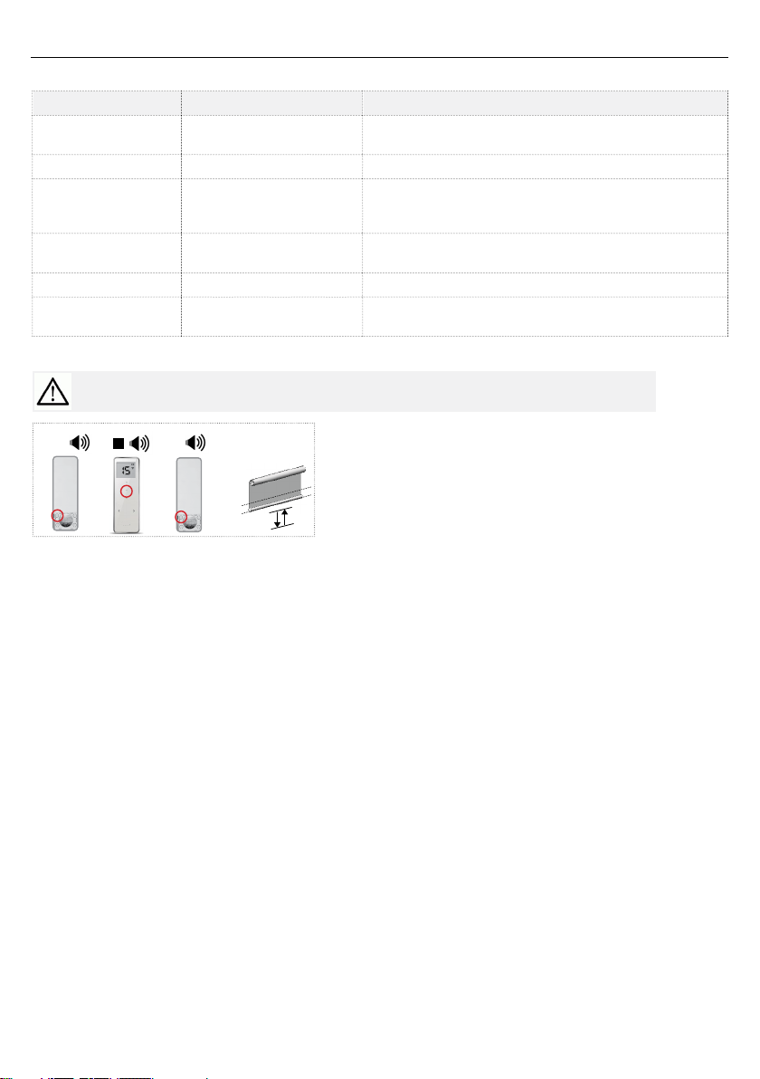
2 Release the key The motor is under the
status of Limit setting
3Press the DOWN key
on the transmitter The motor runs down
4
When the motor is
running close to the
end-point of lower limit,
press STOP
The motor stops running
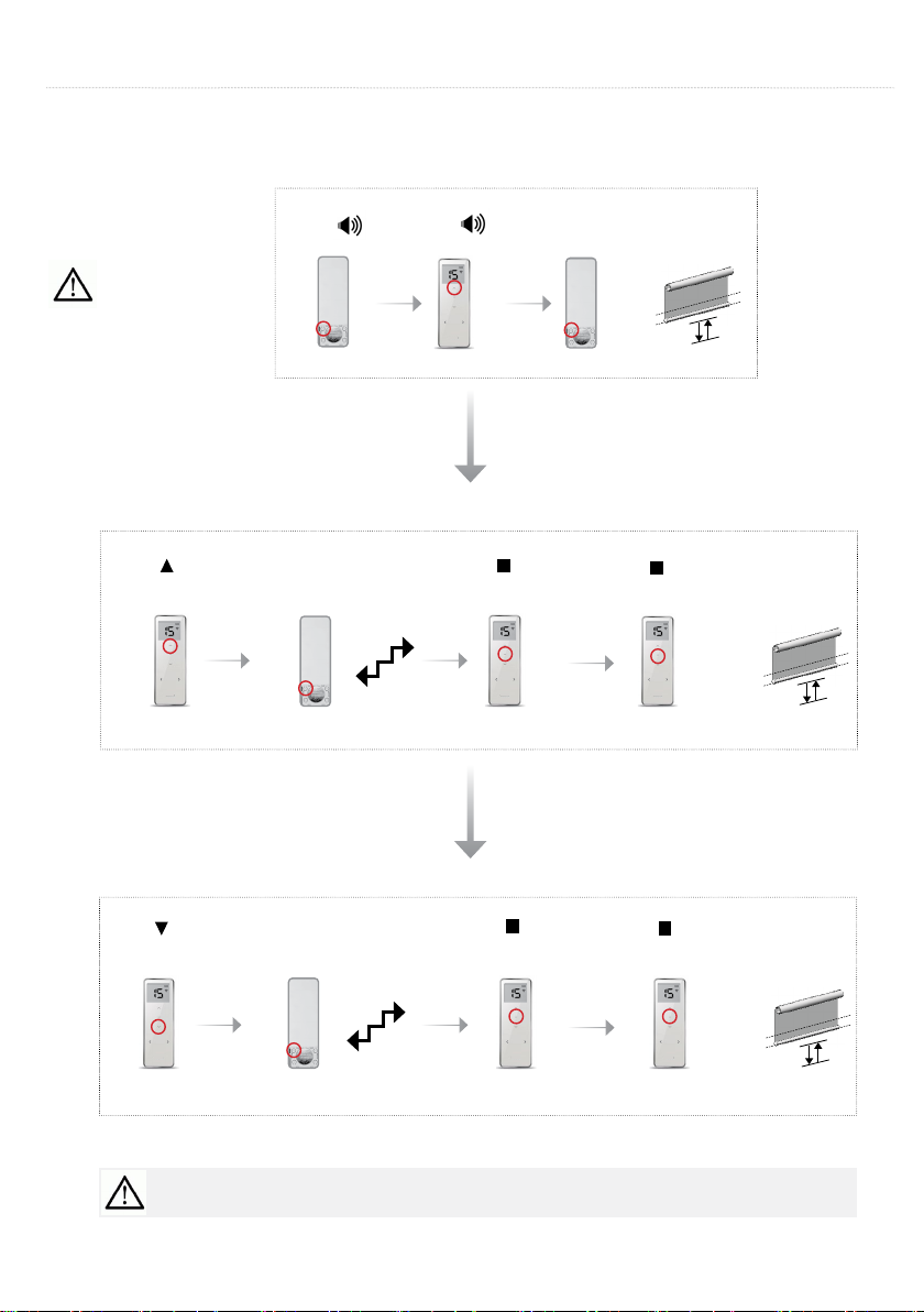
5Press either UP or
DOWN key
The motor runs step by
step to adjust lower limit
accurately
6Press CONFIRM key
on the transmitter
The motor sounds "KA
KA", the setting has
complete.
Setup
upper limit
7Press UP key on
primary transmitter The motor runs up
8
When the motor is
running close to the
end-point of upper limit,
press STOP
The motor stops running
9Press either UP or
DOWN
The motor runs step by
step to adjust lower limit
accurately
10 Press CONFIRM key
on the transmitter
The motor sounds "KA
KA", the setting has
complete.
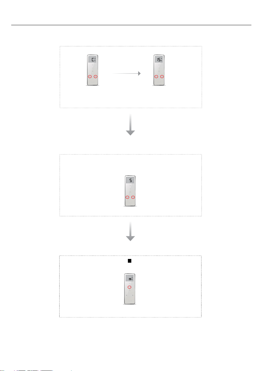
Charging
The motor work with Li-ion battery, please have it charged when the motor stop working or work
faltering. Please plug the charger into the charger hole on the motor head, the charging time is
5 to 6 hours.
FAQ
If nothing works, please check:
●if the motor does not working or works faltering, please charging the motor battery firstly
●If the motor runs to a direction continually, the user didn't setup limit successfully, please re-set
limit.
For instructional purposes, the following options have been shown:
Easy-Lock Chain Winder 'AC' Installation Brackets.
Top Fix installation.
'AC' BracketCover Caps
40mm Motor - Somfy.
Somfy Drive & Crown Wheels.
INSTALLATION
ROLLER BLINDS 40mm MOTORISATION
ENSURE 'NOTCH' OF CROWN WHEEL
LOCKS WITHIN GAP OF MOTOR HEAD.
ASSEMBLY INSTRUCTIONS
STEP 1:
Install Crown Wheel onto40mm Motor. Ensure 'notch' of Crown
Wheellocks within gap of Motor Head.
STEP 2:
Install Drive Wheelonto40mm Motor.
NOTE:
* For Elero Motors, use 'O' ring supplied by Elero to lock Drive Wheel to
40mm Motor.
* For Gaposa Motors, use Gaposa Retaining Clipto lock Drive Wheel
to40mm Motor.
* For Selve Motors, use plastic retaining clip supplied by Selve to lock
Drive Wheelto 40mm Motor.
STEP 3:
Mount 40mm Motor Disk Adaptor onto Motor headwith Counter
Sunk Screws.
ONLY USE WITH GAPOSA
Page 57
=
+
OR
UP
=
P2 P2
Page. 3 of 8
1
1