SoundOFF ETSA380MF User manual

ETSA380MF 2/08
380 SERIES SIREN
ETSA380MF
Package Contents:
1 ea. Amplifier Box with Microphone
1 ea. Microphone Bracket w/ Mounting Hardware
4 ea. Amplifier Wire Harnesses with Connectors (2-12 Pin and 1-5 Pin)
1 ea. Instruction Manual
1 ea. Operators Warning Card to remain in vehicle for operator review
1 ea. Sound Pressure Warning Label that is to be attached in vehicle
and in plain site of operator and occupants of the vehicle
1 ea. Mounting Bracket with Hardware
1 ea. Label Card for Aux. Switches
Wire capacity requirements for siren amplifier
0-10 Feet: 14 AWG
10-20 Feet: 12 AWG
20-30 Feet: 10 AWG
30+ Feet: Consult Factory to determine requirements
IMPORTANT NOTICE TO INSTALLER: Make sure to read
and understand all instructions and warnings before proceeding with the
installation of this product. Ensure the manual and all warning cards are
delivered to the end user of this equipment.
Introduction
The ETSA380MF is Multi-Function Siren Amplifier designed for single or
dual 100 Watt speaker use. The siren comes standard with a
noise-cancelling microphone for PA use. The amplifier box contains a
single amplifier capable of supplying sound to a single 100 Watt speaker.
The ETSA380MF also includes a 4 position slide switch and 8
independently controlled accessory switches each capable of supplying
10-20 amps.
The primary operating modes are User Selectable tone, Yelp, Wail, Radio,
PA, Horn Override, and a push-button Manual Override are available in all
modes. All tones except Wail and Yelp for California Title 13 compliance
may be disabled by programming the siren.
Sirens provide an essential function of an effective audio / visual warning
system. However, sirens are only short range secondary devices. The use
of a siren does not insure that all drivers can or will abide by or react to an
emergency warning signal, especially at high rates of speeds or long
distances. The operator of the vehicle must never take the right of way for
granted and it is the operator's responsibility to proceed safely.
The effectiveness of this siren system is highly dependant on the correct
mounting and wiring. The installer must read and follow the manufacturer's
installation instructions and warnings in the manual. The vehicle operator
should verify the siren system is securely fastened to the vehicle and
properly functioning.
Effective sirens generate loud sound pressure levels that can potentially
cause hearing damage. Installers and those around the vehicle need to be
aware of the dangers and wear hearing protection whenever the siren
system is operating. Vehicle operators and occupants should assess their
exposure to siren noise and determine what steps need to be taken to
prevent hearing damage.
The siren system is intended for use by authorized personnel only. It is the
user's responsibility to ensure they understand and operate the emergency
warning devices in compliance with all applicable city, state, and federal
laws and regulations. SoundOff Signal assumes no liability for any loss
resulting from the use of the siren system.
WARNING: Warning devices are strictly
regulated and governed by Federal, State
and Municipal ordinances. These devices
shall be used ONLY on approved vehicles.
It is the sole responsibility of the user of
these devices to ensure compliance.
WARNING
!
Sirens produce loud sounds that
may damage hearing:
- Roll up windows.
- Wear hearing protection.
- Use only for emergency response.
- Avoid exposure to siren sound
outside of vehicle.
ETSA380MF SHOWN

10 amp
Fuse
ETSA380MF 2/08
380 SERIES SIREN
ETSA380MF
+12V - Push Button #1 Output
+12V - Push Button #2 Output
+12V - Push Button #3 Output
Push Button #8 Normally Open Output
Push Button #8 Input
Push Button #8 Normally Closed Output
10 amp
Fuse
10 amp
Fuse
10 amp
Fuse
RED
BLUE
GREEN
YELLOW
RED/WHITE
RED
WHT/BLK
+12V - Push Button #4 Output
+12V - Push Button #5 Output
+12V - Push Button #6 Output
Push Button #7 Normally Open Output
Push Button #7 Input
Push Button #7 Normally Closed Output
10 amp
Fuse
10 amp
Fuse
10 amp
Fuse
10 amp
Fuse
50 amp
Fuse
50 amp
Fuse
WHT/RED
WHITE
RED/BLK
VIOLET
WHITE
ORANGE
20 amp
Fuse
RED
+12V
+12V
20 amp
Fuse
20 amp
Fuse
BLUE
GREEN
YELLOW
+12V Level 3 Output
+12V Level 2 Output
+12V Level 1 Output
WARNING: Warning devices are strictly
regulated and governed by Federal, State
and Municipal ordinances. These devices
shall be used ONLY on approved vehicles.
It is the sole responsibility of the user of
these devices to ensure compliance.
WARNING
!
Sirens produce loud sounds that
may damage hearing
- Roll up windows.
- Wear hearing protection.
- Use only for emergency response.
- Avoid exposure to siren sound
outside of vehicle.
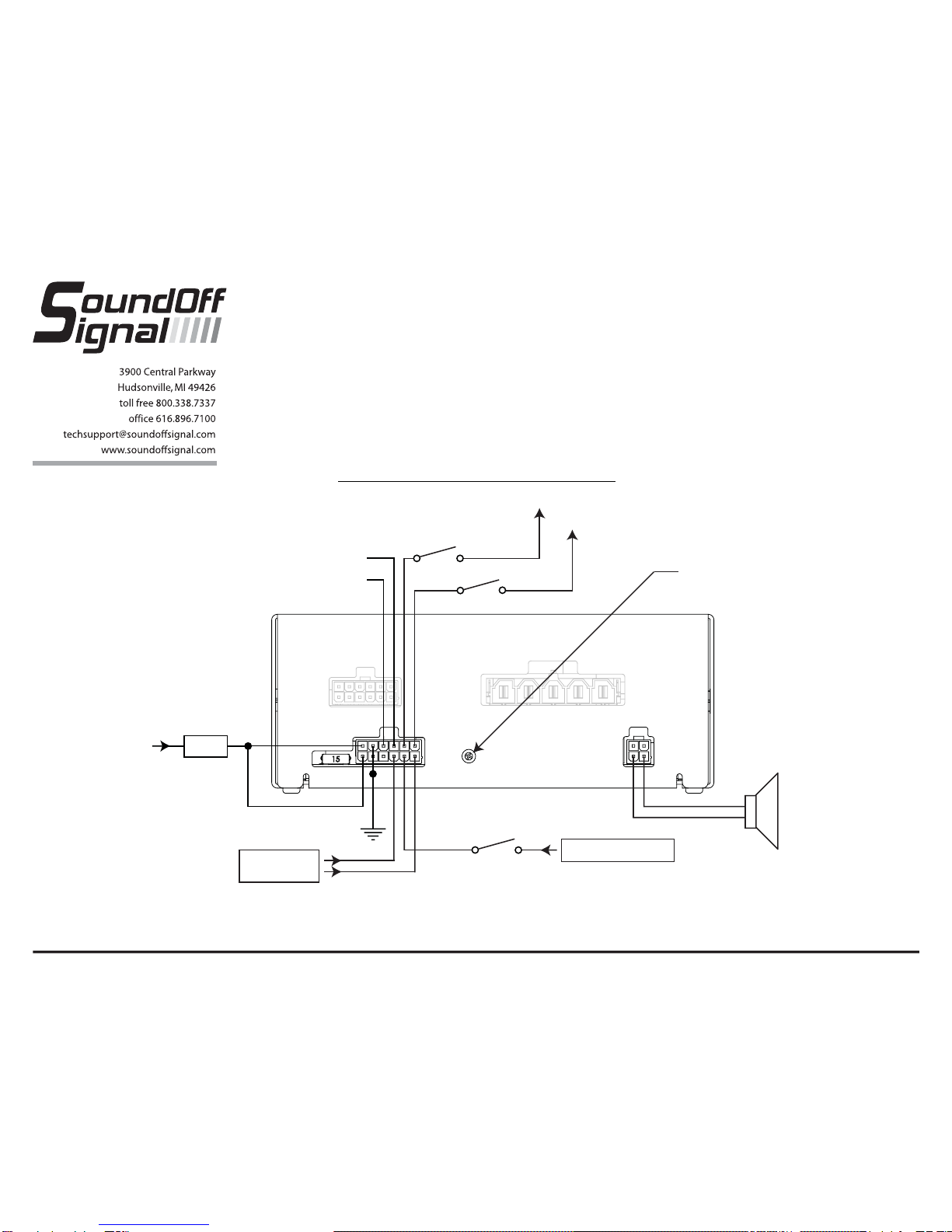
ELECTRICAL CONNECTIONS/INSTALLATIONELECTRICAL CONNECTIONS/INSTALLATION
Note: All fuses shown are user supplied & must be installed to ensure safe operation.
ETSA380MF 2/08
WARNING: Warning devices are strictly
regulated and governed by Federal, State
and Municipal ordinances. These devices
shall be used ONLY on approved vehicles.
It is the sole responsibility of the user of
these devices to ensure compliance.
ELECTRICAL CONNECTIONS/INSTALLATION
+12V 15 amp
Fuse
RED
BLACK
Horn Ring Out
Horn Ring In
+12V
+12V
Violet
Grey
Auxiliary
Backlight
RADIO
REBROADCAST
BLUE
BLUE
Neutral Safety Switch
Park Kill
YELLOW
ORANGE/BLACK
ORANGE
11 Ohm Speaker
100 Watt
380 SERIES SIREN
ETSA380MF
Note: All fuses shown are user supplied & must be installed to ensure safe operation.
Radio Rebroadcast
Output Level Adjust
ETSA380MF 2/08
380 SERIES SIREN
ETSA380MF
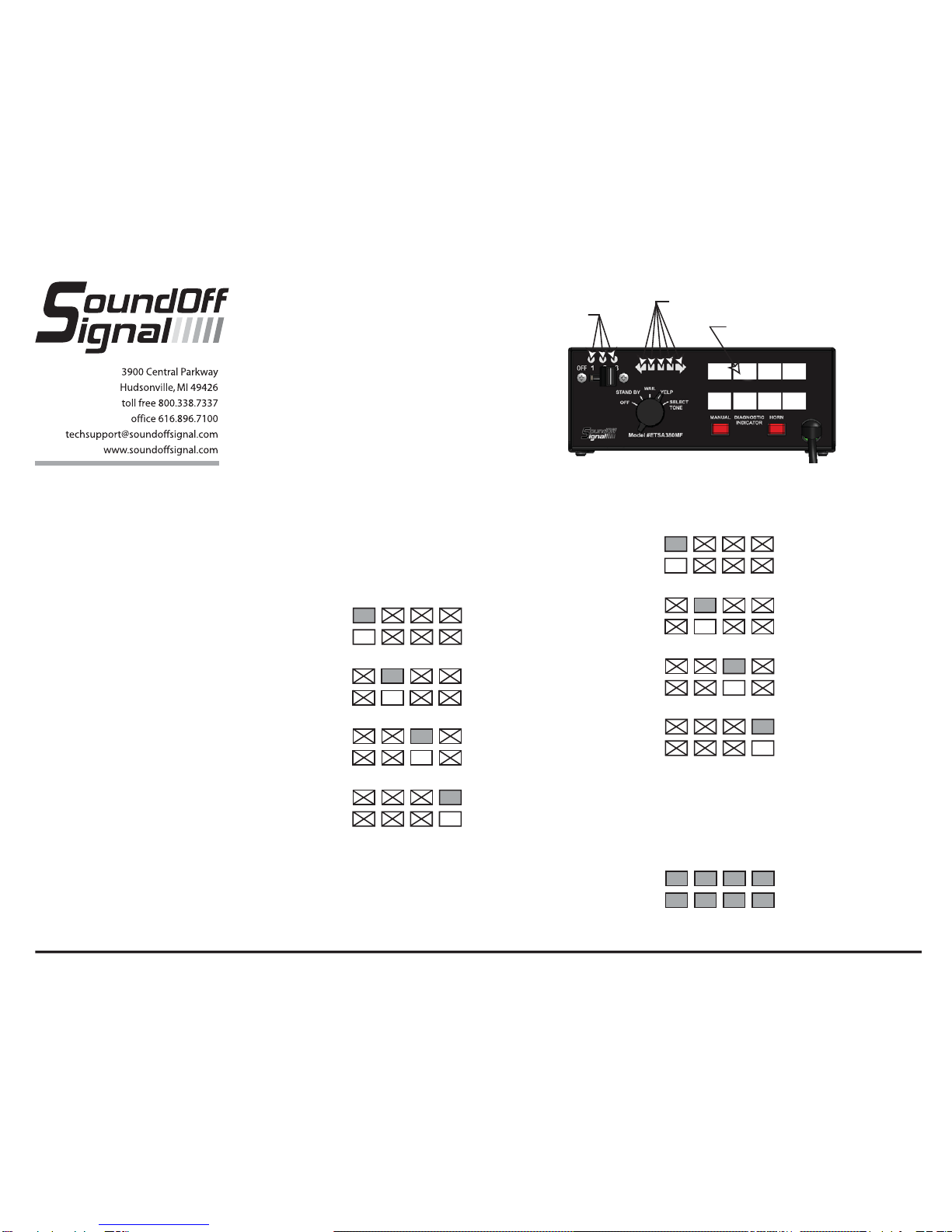
Programming Modes
Auxiliary Switch Settings:
Refer to Figure at right for Button and LED locations and terminology
1. Press and Hold Auxiliary Button #1 and #8 until slide switch #1 LED flashes.
2. Press the button which setting is going to be viewed/changed 1 time.
3. Monitor the 5 LED’s for the arrow controller to determine setting
a. - Arrow Controller (Left, Right, Center, OFF)
b. - Alternate Action Switch (Press ON / Press OFF)
c. - Momentary Action Switch (ON only when depressed)
d. - 8 Second ON Time (ON for 8 seconds when depressed)
e. - Radio Re-Broadcast (Only valid for buttons 6,7, 8)
4. Continue steps 2-3 for any other buttons that need to be programmed.
5. When Finished, momentarily depress PTT button on the microphone to exit
programming mode.
Note: The arrow controller function uses Relay #6 and therefore when a button is
selected for the arrow controller function, button #6 may not be used for
switching functions. In addition, button #6 can’t be used for the arrow control
function since the arrow controller requires the use of 2 relays.
Slide Switch Settings:
1. Press and Hold Auxiliary Button #1 and #4 until slide switch #2 LED flashes.
2. Press Auxiliary switch 1, 2, or 3 depending on which configuration for the slide
switch is required.
3. Auxiliary Switch #1 Illuminated (Mode #1)
a. - Slide Switch Position 1
b. - Slide Switch Position 2
c. - Slide Switch Position 3
4. Auxiliary Switch #2 Illuminated (Mode #2)
a. - Slide Switch Position 1
b. - Slide Switch Position 2
c. - Slide Switch Position 3
AUXILIARY BUTTON #’S
123
4
5678
Slide Switch LEDS
Arrow Control LED’s
5. Auxiliary Switch #3 Illuminated (Mode #3)
a. - Slide Switch Position 1
b. - Slide Switch Position 2
c. - Slide Switch Position 3
6. When finished,momentarily depress PTT button on microphone to exit
programming mode.
Input Settings:
1. Press and Hold Auxiliary Button #1 and #3 until slide switch #3 LED flashes.
a. Park Kill Polarity Mode
= Activate when input connected to Ground
= Activate when input connected to +12V
b.Horn Ring Polarity Mode
= Activate when input connected to Ground
= Activate when input connected to +12V
c. CA Title 13 Compliance Mode
= DISABLED
= ENABLED
d. Level 3 Tone Activation
= Siren Tone is enabled whenever lever is in
position #3.
= Siren Tone is always enabled
2. When finished,momentarily depress PTT button on microphone to exit
programming mode.
Other Modes:
1. Press and Hold Auxiliary Button #1 and #5 until slide switch #1 and #3 LED
flashes.
a. Horn Ring Activation
= Enabled whenever siren is not in“OFF”
position.
= Enabled only when slide switch is in
position 3.
b.TBD
= TBD
= TBD
c.TBD
= TBD
= TBD
d. TBD
= TBD
= TBD
2. When finished,momentarily depress PTT button on microphone to exit
programming mode.
Setting PA Volume:
1. Press and Hold Auxiliary Button #1 and #2 until slide switch #2 and #3 LED
flashes.
a. Depress and hold PA switch on microphone and press Pushbutton 1-8
depending on volume required. When correct volume is determined, release
PA switch on microphone and the volume setting will be permanently stored.
Low 2 34
567 High
ETSA380MF 2/08
SPECIFICATIONS
Input Voltage 10 - 16 VDC (negative ground)
Input Current 16 Amps @ 13.6 VDC (dual 100W speakers)
Standby Current Less than 150 mA
Audio Frequency 200Hz - 10 kHz + 3db
Output Power 100 WATTS RMS MAX. (11 Ohm Speaker Impedance)v
Siren Frequency 675Hz - 1633Hz
High Voltage Protection 15.5 VDC will cause siren output to cease, resume at normal.
Low Voltage Shutdown Voltage below 9.0 Volts for 10 seconds or more will cause siren output to cease and
will resume when system voltage is above 9.0 Volts
Operating
Temperature / Humidity -15° F to +110°F temperature, 5-95% Non-condensing humidity
Controls position rotary switch (Tone, Yelp, Wail, Standby, OFF)
Momentary push-button Horn switch
Momentary push-button Manual switch
Auxiliary Input connection for remote manual or Hands Free operation
Tone disable for California Title 13 compliance
Size Amplifier 2-12” High, 7” Wide, 7” Deep (plus 3/4” flange on each side)
Boxed Weight 8 lbs
Condition LED Indication
Normal Operation ON whenever siren is active (tone, radio, or PA mode)
Shorted Output Flashing Indicator (500mS ON, 500mS OFF) whenever siren is active
Over Voltage 3 fast flashes (200mS ON, 200mS OFF) followed by 2 second delay
Under Voltage 2 fast flashes (200mS ON, 200mS OFF) followed by 2 second delay
No Output Indicator is OFF whenever siren is active (tone, radio, or PA mode)
DIAGNOSTIC INDICATORS
WARRANTY
SoundOff Signal warranties the ETSA380MF Sirens for three (3) year from the date of purchase to
the original purchaser against any manufacturing defects or workmanship. This warranty is a 100%
replacement value warranty. It applies only to units installed according to manufacturer’s installation
instructions and operated within the units specifications. Warranty is void if the unit was installed
incorrectly or maliciously damaged. All warranty claims must be accompanied by a dated proof of
purchase.
SoundOff Signal retains the right to be the sole mediator of what constitutes defects in performance
or manufacturing.
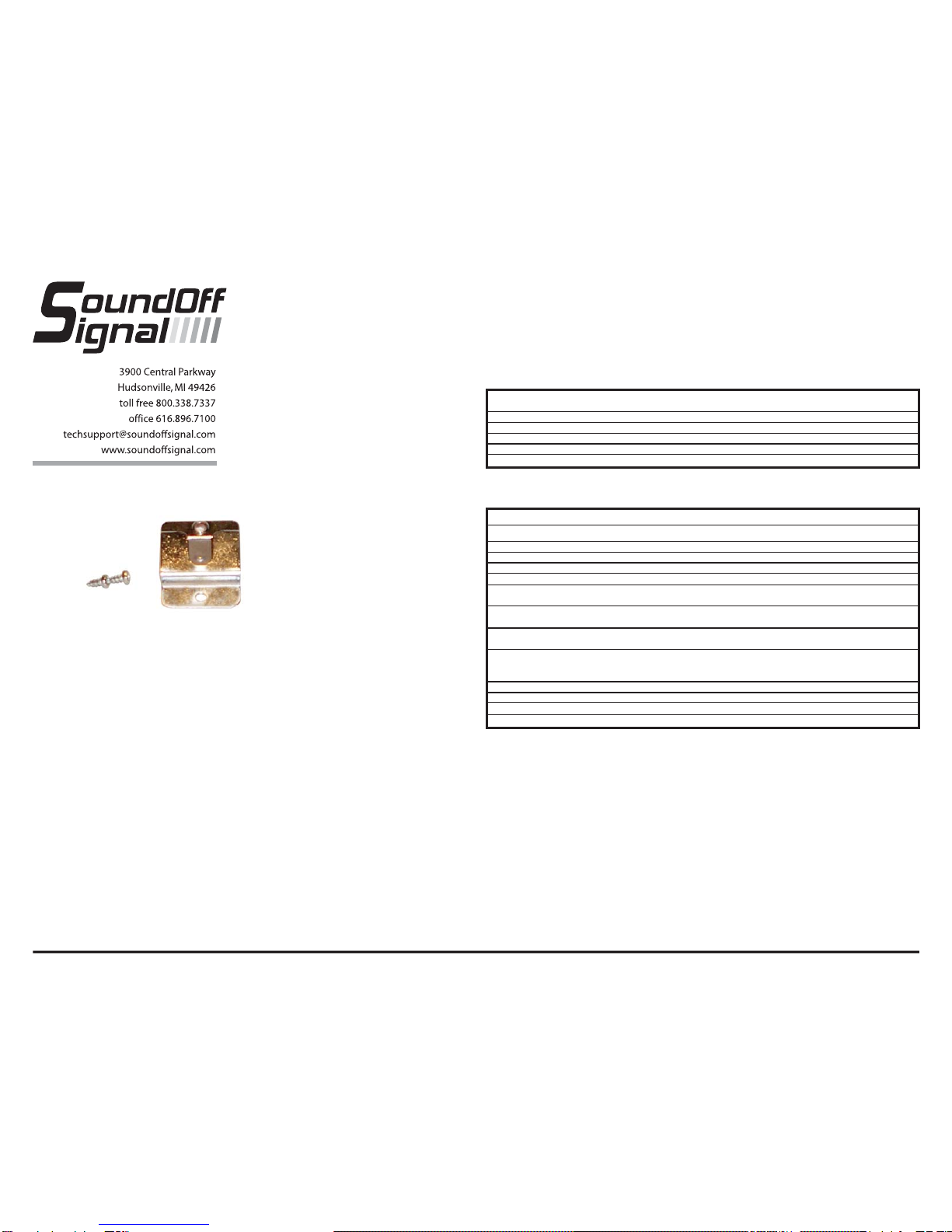
Microphone Bracket Installation:
A metal clip is provided for mounting the microphone.
Choose a location convenient to the operator and away
from any air bag deployment areas. Using the mounting
clip as a template, mark the two holes to be drilled. Using
a 1/8" drill bit, drill the two mounting holes. Install the two
#6 screws provided with the bracket.
380 SERIES SIREN
ETSA380MF
Table of contents


