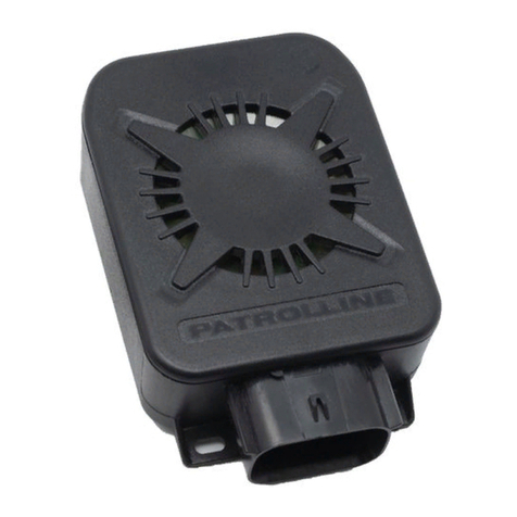
PATROLLINE HPS 940 User manual

PAG.1 DI 14 - REV.0 - COD.: 00-99-940010
HPS 940

PAG.2 DI 14 - REV.0 - COD.: 00-99-940010
Instructions
Thank you for choosing one of our products
The HPS 940 alarm system can be used for the motorcycle or scooter protection. This manual
must be considered like a part of the vehicle, it must be kept for the future reference.
Funzionamento Tramite radiocomando …
arming the alarm system
Press the “A” button of the remote
control or Cyber.
The arming will be confirmed by:
3 acoustic signals (beeps)
3 flashings of the blinkers
Switching on of the LED on the
dashboard
Activation of the electric engine
immobilization.
All the instructions concerning
the use of the remote controls
refer to these pictures
Disarming the alarm system
Press the “A” button of the remote
control or Cyber.
The disarming will be confirmed by:
1 acoustic signal (beep)
1 long flashing of the blinkers
Switching off of the LED on the
dashboard
Deactivation of the electric engine
immobilization
Signalling of alarm memory – when
needed (indicator lights and beep).
Siren Exclusion…
During the first 5 seconds of arming (LED fixed), it’s possible to exclude the siren sound pressing the button “B” of
the remote control. Two acoustic signals will confirm that the siren sound has been excluded.
In this case the central unit will signal the alarm state only by the flashing of the indicator lights.

PAG.3 DI 14 - REV.0 - COD.: 00-99-940010
Alarm state and Alarm…
After the alarm arming (LED fixed), the central unit is ready to signal every attempt of theft. The alert state is
signalled by the flashing of the LED installed on the dashboard.
In case of effraction, shock, lighting of the console, opening of tele alarms (if installed), opening of protected vain or
prop-stand, the system will emit an optic-acoustic signal (indicator lights flashing and siren sound) for 30 seconds.
To interrupt the signalling without disconnecting the alarm, depress the button “B” of the remote control.
To interrupt the signalling and disconnect the system, depress the button “A” of the remote control.
Acoustic limitation for consecutive alarms…
During the alert state, if the alarm sensors notice for 3 consecutive times a cause of alarm, at the fourth cause of
alarm the central unit will exclude the siren signalling the alarm state only with the flashing of the indicator lights.
However, during this phase the electric block of the engine is active.
Warning: in case the ignition key is turned on or the “button B” of the remote control is depressed (panic alarm),
the siren sound is restored.
PANIC alarm…
After 5 seconds arming (LED flashing), press the button “B” of the remote control: the central unit give 28 seconds
alarm cycle. To interrupt the alarm cycle, press again the button “B”.
HAZARD function…
It is possible to switch on the 4 blinkers of the motorcycle (Hazard function) pushing the button “C” of the remote
control. The central unit turn on the blinkers flashing for an indeterminate period. This function is available both
with key position turn on or off. To stop the blinker’s flashing push again the button “C”. The exclusion of the
function will be signalled by a beep.

PAG.4 DI 14 - REV.0 - COD.: 00-99-940010
Alarm memory…
If the central unit records one or more causes of alarm, they are signalled when disarming, by a further flashing of
the indicator lights and number of “beeps” equal to the happened alarms (max 7 signalling).
Battery backup…
HPS 940 is equipped with self-powered battery that guarantees its operation in case of main power supply wiring is
cut. The battery backup is automatically armed when the black connector of the alarm wiring is connected.
Memory state…
During the alert state, if the alarm is disarmed by the mechanical key or it is detached from the cable harness, when
restored it will “remember” the state in which it was, preventing in this way every attempt of tampering.
Release code using…
It must be used to disconnect the system when the remote controls don't work or are lost and the central unit is still
armed:
The code is always a number of 3 figures (from the factory it is: 1-2-3) and it must be composed with the ignition key
performing this procedure (with the alarm armed):
1. Turn on and off the ignition key as many times as the value of the first figure is (1 time in the case of code of
factory).
During the composition of the secret code, the LED on the dashboard remains turned on and the siren plays.
Wait for the LED on the dashboard to be OFF.
2. Turn on and off the ignition key as many times as the value of the second figure is (2 times in the case of code of
factory)
3. Wait for the LED on the dashboard to be OFF.
4. Turn on and off the ignition key as many times as the value of the third figure is (3 times in the case of code of
factory)
If the operation is correct, after the third figure the system is disarmed.

PAG.5 DI 14 - REV.0 - COD.: 00-99-940010
Change of release code…
This operation allows to personalize the secret release code from the one of factory (1-2-3) to the desired one:
1. By the ignition key, compose the old secret code as described in the previous paragraph.
2. Wait for 4 flashes of the indicators lights as confirmation that the old release code is correct.
3. Turn on and off the ignition key as many times as the value of the first figure that you want to modify is.
During the composition of the secret code, the LED on the dashboard remains turned on.
4. Wait for the LED on the dashboard to be OFF.
5. Turn on and off the ignition key as many times as the value of the second figure that you want to modify is.
6. Wait for the LED on the dashboard to be OFF.
7. Turn on and off the ignition key as many times as the value of the third figure that you want to modify is.
If the operation is correct, after the third figure the alarm will emit a series of beeps and it will make the LED flashing
as confirmation that the new release code has been memorized and has replaced the previous one.
If the procedure is not correct, the alarm will emit a beep and the release code won't result changed.
During the phase of regulation, it is possible to test the sensor sensibility by striking the vehicle.
The phase of regulation finishes turning the ignition key in position OFF or after 6 seconds from the last pressure on
the buttons of the remote control.
In case of lack of feeding, the central unit restores the sensibility set by factory.

PAG.6 DI 14 - REV.0 - COD.: 00-99-940010
Programmable functions…
HPS 940 can modifies the common features by following this procedure:
1. During the system disarmed (LED off), compose the “secret release code” by the ignition key (see paragraph
“Use of the Secret Release code”). At the end, the indicator lights will quickly flash to confirm that the release
code is correct.
2. Compose by the ignition key the figure 4 (turn on and off the ignition key for 4 times consecutively).
A beep will confirm that the modification procedure is started.
3. Press in the same time the button “A” and the button “B” of the remote control.
Maintain the buttons depressed until you get the beeps corresponding to the function you want to modify.
Once reached the position that you want to modify, release the buttons of the remote control. After few seconds:
the LED is ON, it confirms the activation of the corresponding function. Or
the LED is OFF, it confirms the deactivation of the corresponding function.
N° BEEP
Description
DEFAULT
1 beep
Exclusion of Acoustic Signals of Arming and Disarming
Disarmed
2 beeps
Hazard Signalling
Disarmed
3 beeps
Acoustic Signalling of Inserted Indicator Lights
Disarmed
Check the programmed functions…
It is possible to verify the state of the 14 functions programmed by the acute or deep sounds given by the alarm.
With the system disconnected (LED off), compose the “secret release code” by the ignition key (see
paragraph “Use of the Secret release code”)
At the end, the indicator lights will quickly flash to confirm that the release code is correct.
Compose, by the ignition key, the figure 2 (turn on and off the ignition key for 2 times consecutively).
If the function corresponding to the number of the LED flashing is disarmed, a beep of acute tonality will be heard.
If the function corresponding to the number of the LED flashing is activated, a beep of deep tonality will be
heard.

PAG.7 DI 14 - REV.0 - COD.: 00-99-940010
Programmable functions description…
1. Deactivation of ON – OFF acoustic signals
Arming or disarming the alarm system depressing the “button A” is signalled via a blinkers flash as well as an
acoustic warning. It may sometimes be necessary the exclusion of the acoustic warning and having a silent signalling.
Arming/disarming depressing the “button A” in this case will be signalled via blinkers only.
2. Hazard signalling
Activating this function, it is possible to signal the standstill of the vehicle by the indicator lights. With the function
activated, turn the ignition key in position ON and make the indicator lights flashing once. The central unit will make
the indicator lights flashing for an indefinite time. It is possible to interrupt the signalling by turning on an indicator
light or by pressing the “button B” of the remote control. The exclusion of this function is signalled by a beep.
3. Acoustic signalling of inserted indicator light
Using the vehicle, it can happen to forget an indicator light inserted. In this case, after 32 flashes of the indicator
light (right or left indifferently), the alarm will signal this forgetfulness to the driver with a brief acoustic signal. If the
indicator light remains activated (e.g. you are at a crossroads and the waiting time is quite long), the alarm will
repeat the acoustic signal after 12 flashes of the indicator light and so on.
Deleted of the programmed functions …
It is possible to reset all the programmed functions and to bring the alarm in the basic configuration, in the case you
are not sure about the programmed functions and you want to cancel all them (as reported in the programming
table).
With the system disconnected (LED off), compose the “secret release code” by the ignition key (see
paragraph “Use of the Secret Release code”).
At the end, the indication lights will quickly flash to confirm that the release code is correct.
Compose by the ignition key the figure 9 (turn on and off the ignition key for 9 times consecutively).
To confirm the cancellation, the alarm will emit a series of BEEPS.

PAG.8 DI 14 - REV.0 - COD.: 00-99-940010
Shock sensor adjustment …
The shock sensor is already adjusted by our laboratories, in such a way to have a good compromise between alarm
sensibility and prevention against the false alarms. In the case it was necessary to change the sensibility, it must be
followed this procedure with the alarm disarmed:
Turn the ignition key in position ON.
In the first 5 seconds, depress the “button A” to increase the sensibility.
or the “button B” to decrease the sensibility.
A series of beeps in increasing tonality points out the increase of the sensor sensibility.
The repetition of the most acute sound points out that the greatest sensibility of the sensor has been reached.
A series of beep in decreasing tonality points out the diminution of the sensor sensibility.
The reduction of sensibility finishes with the exclusion of the sensor signalled by 3 consecutive beeps.
NEW remote-control learning…
This procedure allows to combine new remote controls or tele alarms with the alarm (MAX 8)
1. With the system disconnected (LED off), compose the “secret release code” by the ignition key (see
precedent paragraph).
2. At the end, the indicator lights will quickly flash.
3. Compose by the ignition key the figure 3 (turn on and off the ignition key for 3 times consecutively).
4. The LED lights fixed for 10 seconds confirming that the procedure is started.
5. During this time (LED on), depress any key of the new remote control to be combined to the alarm.
An acoustic signal and the turning off of the LED will signal that the learning is completed.
Optional modules…
Tele alarm (HPA 940): it is a magnetic perimetral sensor that transmits the opening signal via radio. Using the system
of transmission in radio frequency, it can be installed also on the vehicle next to the motorbike on which the alarm is
installed.

PAG.9 DI 14 - REV.0 - COD.: 00-99-940010
Alarm system maintenance…
VEHICLE CLEANING: If the vehicle had to be washed with high-pressure devices (hydro beam or similar), it is
necessary to protect the alarm before beginning the washing. If you are not sure to sufficiency protect
the alarm or if the washing must have done in all the parts of the vehicle, the alarm must be removed
from its own place. In case of water's infiltrations caused by use of hydro beam, the guarantee will lapse.
REMOTE CONTROLS: The remote controls, for their own functioning, use some alkaline batteries easily available on
the market. If a remote control is not used for quite a lot time, the inside battery must be removed to prevent
damages caused by escapes of acid from the battery itself. Besides, the remote controls must not have submitted to
violent shocks, and they won't have to suffer immersions in any type of liquid. A progressive diminution of the
transmission range, points out that the battery of the remote control is unloading. Replacing immediately the
battery will avoid to have the alarm armed and the remote control unusable.
GENERAL MAINTENANCE: All the operations to repair the alarm must be performed by PATROL LINE
Assistance Centres. The tampering of the alarm by personal not qualified can jeopardize the device
working and the safety of the vehicle.

PAG.10 DI 14 - REV.0 - COD.: 00-99-940010
Generic wiring diagram connections
Warning The alarm must be installed by a qualified person following carefully the indications of the manufacturer. The person who do the
installation must fill in the installation certificate attached. The homologation number of the alarm can be found on the user’s manual or on
the label located on the plastic box of the alarm. Every following modification to the device or to the connections of the alarm invalidates the
installation certificate.

PAG.11 DI 14 - REV.0 - COD.: 00-99-940010
Precautions for the installer
CENTRAL UNIT POSITION:
Locate in the vehicle a good place to install the central unit. This location must protect the device from water but
must also allow a good sound of the siren. Once the installation is over, shut with the wrapper the protecting rubber
cover of the alarm.
ELECTRIC CONNECTIONS:
They must be perfectly performed, otherwise they will provoke, in time, problems to the alarm and the vehicle
working.
GENERAL MAINTENANCE:
All the operations to repair the alarm must be performed by PATROL LINE Assistance Centres. The tampering of the
alarm by personal not qualified can jeopardize the device working and the safety of the vehicle.
FIXING OF THE WIRING TO THE ALARM:
Connect the plastic part of the wiring to the alarm and close with the supplied. Before the closing verify the presence
of the o-ring rubber on the plastic part of the wiring.
DEVICE MAINTENANCE:
The installer, when delivering the vehicle, must advise his customer that, if he wants to wash it with high-pressure
devices (hydro beam or similar), it is necessary to protect the alarm before beginning the washing. In case of water's
infiltrations caused by use of hydro beam, the guarantee will lapse.
A progressive diminution of the transmission range, means that the remote-control battery is unloading. Replace the
battery immediately will avoid to have the alarm inserted and the remote control unusable.

PAG.12 DI 14 - REV.0 - COD.: 00-99-940010
Conformity declaration and Technical features
CONFORMITY DECLARATION
This product is in conformity with the
European Directive 95/56/CE, regarding the
functionality of the alarm devices, and
therefore it satisfies all the requirements
asked by the European Directive for the
electromagnetic compatibility.
The installation certificate of the alarm,
included in the packaging, must be carefully
filled in every part and it will belong to the
vehicle documentation.
POWER SUPPLY 11V ÷ 15V
ALARM ARMED COMSUMPTION < 1,5 mA
BLINKERS RELAY MAX CURRENT 5 + 5A
ENGINE BLOCK RELAY MAX CURRENT 5 A
NEUTRAL TIME < 5 sec.
ALARM CYCLE DURING < 30 sec.
SOUND POWER 113 dBA
REMOTE-CONTROL RANGE 10 metri
REMOTE-CONTROL FREQUENCY 433.92 MHz
OPERATING TEMPERATURE -40°C / +85°C
WATERPROOF IP 64
SELF POWERED INTERNAL BATTERY 7,2V 60mA NI-MH
DIMENSIONI 90 x 58 x 24
PESO 92 gr.

PAG.13 DI 14 - REV.0 - COD.: 00-99-940010
Warranty conditions …
PATROLLINE guarantees the device against manufacturing defects for a period of 24 months from the date of
delivery. The warranty consists in free replacing or repairing of parts unusable or inefficient because of factory’s
fault verified by Patrolline. Any delay in carrying out works do not entitle to damages or extension of warranty.
The warranty lapses if the devices are used not in conformity with the present conditions, if they are modified,
repaired or tampered, if the defects derive from accidents, from negligence or from using parts not original. What
above-mentioned is the only warranty, that therefore substitutes the legal one. The buyer has not the right to ask
for the annulment of the contract, to claim compensation or price reduction.
RESPONSIBILITY: Patrolline has no responsibility or obligations for any accident and/or damage to things/people that
could occur using the device.
LIMITATIONS: the buyer undertakes to not to use the device for purposes different from the ones it is for, and to
not to modify its construction and its functioning. Saved any possible action of compensation for damages, it is
agreed that the non-observance of the regulations above-mentioned involves the immediate end of the right of
warranty.
Enforcement formality …
The validity starts from the date of delivery (that is the date of the first installation) signed on the warranty
special coupon with the receipt attached or a copy of the invoice. Without these documents, the warranty will
start from the date of manufacturing.
The following services are free: the supply and replacement of the parts unusable or inefficient because of
verified defect of material; the labour to replace and repair the above-mentioned parts; the supply of materials
that have become necessary after the above-mentioned actions and pertinent to them.
Are payable by the buyer: the replacement of various materials not connected with the interventions to repair
the device for verified defect; maintenances and interventions because of wear, accident or conditions that do
not follow the indications of Patrolline.
Every piece returned, for any reason, to Patrolline will be done by PORTO FRANCO.
These conditions of warranty have to be considered valid only on National territory (Italy).

PAG.14 DI 14 - REV.0 - COD.: 00-99-940010
Installation Certificate
The undersigned ________________________________________________________
professional installer, certify that the installation of the vehicle protection device described below has been done in
conformity with the instructions given by the manufacturer.
Description of the vehicle:
Brand and Model ____________________________________________________________________________
Description of the vehicle protection device:
Model and Serial Number _____________________________________________________________________
Place and date of the installation:
________________________________________________________
MALFUNCTION (minutely describe the problem):
_______________________________________________________________
_______________________________________________________________
______________________________________________________________________________________
______________________________________________________________________________________
______________________________________________________________________________________
______________________________________________________________________________________
PATROLLINE GROUP Società Cooperativa
Via C. Cantù 15/C 22031 Albavilla (CO) ITALY
Tel: +39.031.0352088 Fax: +39.031.0352089
E-mail: [email protected] Web: www.patrolline.it
Stamp and signature
of the installer
Table of contents
Other PATROLLINE Security System manuals
