manuals.online logo
Brands
  1. Home
  2. •
  3. Brands
  4. •
  5. Soundstream
  6. •
  7. Amplifier
  8. •
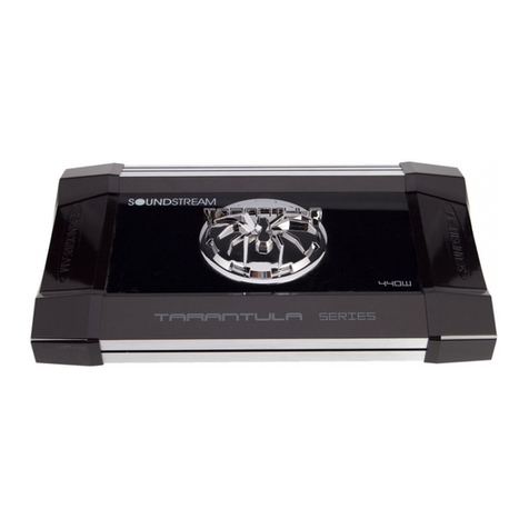
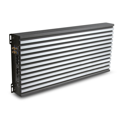
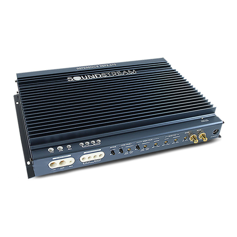
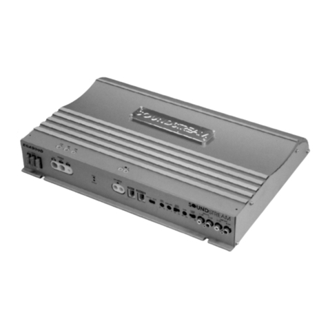
  9. Soundstream TARANTULA NANO User manual

Soundstream TARANTULA NANO User manual

NANO
LIMITED 90-DAY CONSUMER WARRANTY
LIMITED TWO-YEAR CONSUMER WARRANTY WITH PURCHASE AND INSTALLATION BY A SOUNDSTREAM
AUTHORIZED DEALER
Soundstream promises to theoriginal purchaser, to repairor replacethisproductwith anew or refurbished
unit(at Soundstream’ssoleand absolute discretion) shoulditproveto bedefectiveinworkmanship or
material under normal use, for aperiod of *two-years from thedate of purchase from theSoundstream
authorized dealer, PROVIDED theproductwas purchased and installed by aSoundstream authorized dealer.
During this*two-year period, therewill beno chargefor productrepairor replacement, PROVIDED theunitis
returned to Soundstream, return shipping pre-paid, along with therequired proof of installation, thebill of
saleor other dated proof of purchase, and theconsumer’scontactinformation.
If theunitisinstalled by anyone other than aSoundstream authorized dealer, thewarranty period will be
90-daysfromthedate of purchase. Thiswarranty isnon-transferableand does not apply to any unitthat has
been modied or used inamanner contrary to its intended purpose, and does not cover damageto theunit
caused by installation or removal of theunit. During this90-day period, there will beno chargefor therepairor
replacement PROVIDED theunitisreturned to Soundstream, return shipping prepaid, along with thebill of
saleor other dated proof of purchase and theconsumer’scontactinformation.
Thiswarranty isvoidif theproducthas been damaged by accident or unreasonableuse, neglect, improper
serviceor other causes not arising out of defects inmaterialsor construction. Thiswarranty does not cover the
elimination of externally generated static or noise, or thecorrection of antenna problems or weak reception,
damageto speakers, accessories, electrical systems, cosmetic damageor damagedue to negligence, misuse,
failure to follow operating instructions, accidental spillsor customer applied cleaners, damagedue to environ-
mental causes such as oods, airborne fallout, chemicals, salt, hail, lightning or extreme temperatures, damage
due to accidents, road hazards, re, theft, loss or vandalism, damagedue to improper connection to equipment
of another manufacturer, modication of existing equipment, or Productwhich has been opened or tampered
for any reason. Units which arefound to bedamaged by abuse resulting inthermally damaged voicecoilsare
not covered by thiswarranty but may bereplaced at theabsolute and solediscretion of Soundstream. Unit
must bereturned to Soundstream , postagepre-paid, with bill of saleor other dated proof of purchase bear-
ing thefollowing information: consumer'sname, telephone number, and address, authorized dealer'sname
and address, and productdescription. Please contactSoundstream warranty oceat 800-724-1377 or
repairs@soundstream.com to obtainaReturn Authorization number prior to shipping theproduct.
Note: Thiswarranty does not cover labor costs for theremoval and reinstallation of theunit. IN ORDER FOR THE
TWO-YEAR WARRANTY TO BE VALID, YOUR UNIT MUST BE SHIPPED WITH PROOF OF INSTALLATION BY A SOUND-
STREAM AUTHORIZED DEALER. ALL UNITSRECEIVED BY SOUNDSTREAM FOR WARRANTY REPAIR WITH-
OUT PROOF OF SOUNDSTREAM AUTHORIZED DEALER INSTALLATION AND PURCHASE WILL BE COVERED BY
THE LIMITED 1 YEAR WARRANTY.
BY PURCHASING THISPRODUCT, ALL WARRANTIESINCLUDING BUT NOT LIMITED TO EXPRESS WARRANTY,
IMPLIED WARRANTY, WARRANTY OF MERCHANTABILITY, FITNESS FOR PARTICULAR PURPOSE, AND WARRANTY
OF NON-INFRINGEMENT OF INTELLECTUAL PROPERTY ARE EXPRESSLY EXCLUDED TO THE MAXIMUM EXTENT
ALLOWED BY LAW, AND SOUNDSTREAM NEITHER ASSUMESNOR AUTHORIZESANY PERSON TO ASSUME FOR
IT ANY LIABILITY IN CONNECTION WITH THE SALE OF THE PRODUCT. SOUNDSTREAM HASABSOLUTELY NO
LIABILITY FOR ANY AND ALL ACTSOF THIRD PARTIESINCLUDING ITSAUTHORIZED DEALERSOR INSTALLERS. BY
PURCHASING THISPRODUCT, THE CONSUMER AGREESAND CONSENTSTHAT ALL DISPUTESBETWEEN THE
CONSUMER AND SOUNDSTREAM SHALL BE RESOLVED IN ACCORDANCE WITH CALIFORNIA LAWSIN LOS
ANGELESCOUNTY, CALIFORNIA. Some states do not allow limitation on how long an implied warranty lasts. In
such states, thelimitation or exclusions of thisLimitedWarranty may not apply. Some states do not allow the
exclusion or limitation of incidental or consequential damages. Insuch states, theexclusion or limitation of this
LimitedWarranty may not apply to you. ThisLimited Warranty gives you specic legal rights, and you may have
other rights which vary from state to state.

1. Remote Level Control Connection
Connect the remote level control to this terminal.The remote level
control allows adjustment ofthe subwoofer level from a remote
location in the vehicle.
2. Low Pass Crossover
Adjust the frequencysettingofthe lowpass crossover.The
frequencyrange is 40Hz-220Hz. Frequencies higher than the
3. Subsonic Crossover
Adjust the frequencysettingofthe subsonic crossover.The
frequencyrange is 20Hz-38Hz. Frequencies lower than the setting
4. Protection Indicator LED
red.Refer to the TroubleshootingGuide for possible solutions if
5. Power Indication LED
LED will illuminate green.Refer to the TroubleshootingGuide
6. Level Sensitivity
sensitivitylevel is 200mv, while the maximum level is 6V.
7. RCA Audio Input Connection
Usinghigh qualityshielded stereo RCA cables,connect the
8. RCA Audio Output Connection
Usinghigh qualityshielded stereo RCA cables,connect the
audio signal to the RCA audio inputs ofadditional system
components.
9. Bass Boost
TN1.1200D Pre-Amp
TN1.1200D Pre-Amp Panel
9
TN1.1200D
TN1.1200D Wire Connections
TN1.1200D Wire Connections End Panel
1. Power Connection Terminal
GND Connectgood quality 8ga. ground wire to thenearest
vehiclechassisground. Takeamoment to properly prepare the
ground location for thebest ground.
REM Connecttheremote turn-on output of thesourceunitto
theremote terminal.
+12V Connectgood quality 8ga. power wire to thevehicle’s
battery. Alwaysprotectthevehicleby using afuse within18”
from thebattery.
2. Fuses
Thefuses protecttheamplier from internal electrical damage
if overloaded. Intheevent they fail, replacewith similar type
and amperagevalue. Using ahigher amperagevalue may lead
to electrical damageand isnot considered covered by the
limited warranty.
3. Speaker Connection Terminal
Connectthesubwoofer(s) to thecorresponding (+) & (-)
terminals. If only one subwoofer with 1Ω isused, use only one
(+) & (-) terminal. If twosubwoofers are used with 2Ω each, use
one (+) & (-) terminal for each subwoofer.
NOTE: Twosubwoofers with 1Ω each CAN NOT beconnected to
separate (+) & (-) terminals. Thewoofers shouldberst series
wired together for 2Ω, then use only one (+) & (-)
123
TN1.1200D
Power Rating
RMSOutput Power, 14.4V, 4Ω 660w x1
RMSOutput Power, 14.4V, 2Ω 1,050wx1
RMSOutput Power, 14.4V, 1Ω 1,200w x1
RMSOutput Power, 12.0V, 4Ω 466w x 1
RMSOutput Power, 12.0V, 2Ω 610w x 1
RMSOutput Power, 12.0V, 1Ω 900w x 1
Pre-Amp Features
Low Pass Crossover 40Hz-220Hz 12db
Subsonic Crossover 20Hz-38Hz 12db
Bass Boost 45Hz, 0dB-12db
Input Level Sensitivity 200mV-6V
IdleCurrent Draw 1.98A
12V Ground Isolation 10k Ohm
Damping Factor 91
Input Impedance105k Ohm
Signal-to-Noise Ratio106dB
Fuse Rating 40A x 3
Dimensions 12.75''LX6.75''WX1.75''H(INCH)
TN2.600D Pre-Amp
TN2.600D Pre-Amp Panel
1. RCA Audio Output Connection
Usinghigh qualityshielded stereo RCA cables,connect the
audio signal to the RCA audio inputs ofadditional system
components.
2. RCA Audio Input Connection
Usinghigh qualityshielded stereo RCA cables,connect the
source signal outputs to the amplifer RCA inputs.
3. Level Sensitivity
Adjust the amplifers pre-ampsensitivitylevel.The minimum
sensitivitylevel is 200mv, while the maximum level is 6V.
4. Power Indication LED
When the amplifer is on and in proper workingcondtion,this
LED will illuminate green.Refer to the TroubleshootingGuide
for possible solutions if the amplifer will not power on.
5. Protection Indicator LED
If the amplifer activates protection mode,this LED will illumi-
nate red.Refer to the TroubleshootingGuide for possible
solutions if the amplifer activates protection mode.
6. High Pass Crossover
Adjust the frequencysettingofthe High Pass Crossover.The
frequencyrange is 20Hz-4kHz. Frequencies lower than the
7. Crossover Frequency Multiplier
Use the frequencymultiplier to change the High Pass Crossover
frequencyrange x10.
8. Low Pass Crossover
Adjust the frequencysettingofthe LowPass Crossover.The
frequencyrange is 50Hz-5kHz. Frequencies higher than the
9. Crossover Frequency Multiplier
Use the frequencymultiplier to change the LowPass Crossover
frequencyrange x10.
10. Crossover Selector Switch
Choose to activate the High Pass Crossover,LowPass Crossover,
or Band Pass Crossover.Band Pass Crossover uses the high pass
and lowpass crossovers simultaneously.
TN2.600D
TN2.600D Wire Connections
TN2.600D Wire Connections End Panel
1. Speaker Connection Terminal
Connectspeaker(s) with aminimum impedanceof 2Ω to the
corresponding (+) & (-) terminals.
If one subwoofer with 4Ω isused, bridgetheamplier using
the(R+) & (L-) terminal. If twosubwoofers are used with 2Ω
each, use one (+) & (-) terminal for each subwoofer.
2. Fuses
Thefuses protecttheamplier from internal electrical damage
if overloaded. Intheevent they fail, replacewith similar type
and amperagevalue. Using ahigher amperagevalue may lead
to electrical damageand isnot considered covered by the
limited warranty.
3. Power Connection Terminal
GND Connectgood quality 8ga. ground wire to thenearest
vehiclechassisground. Takeamoment to properly prepare the
ground location for thebest ground.
REM Connecttheremote turn-on output of thesourceunitto
theremote terminal.
+12V Connectgood quality 8ga. power wire to thevehicle’s
battery. Alwaysprotectthevehicleby using afuse within18”
from thebattery.
TN2.600D
Power Rating
RMSOutput Power, 14.4V, 4Ω 200w x 2
RMSOutput Power, 14.4V, 2Ω 300w x 2
RMSOutput Power, 14.4V, 4Ω Bridged 600w x 1
RMSOutput Power, 12.0V, 4Ω 100w x 2
RMSOutput Power, 12.0V, 2Ω 200w x 2
RMSOutput Power, 12.0V, 4Ω Bridged 400w x 1
Pre-Amp Features
Low Pass Crossover 50Hz-5kHz 12db
High Pass Crossover 20Hz-4kHz 12db
Input Level Sensitivity 200mV-6V
IdleCurrent Draw 0.93A
Damping Factor 114
Input Impedance20k Ohm
Signal-to-Noise Ratio94dB
Fuse Rating 25A x 2
Dimensions 6.825''LX6.75''WX1.75''H(INCH)
TN4.900D Pre-Amp
TN4.900D Pre-Amp End Panel
1. Front RCA Audio Input Connection
Usinghigh qualityshielded stereo RCA cables,connect the
2. Front Level Sensitivity
sensitivitylevel is 200mv, while the maximum level is 6V.
3. Front High Pass Crossover
Adjust the frequencysettingofthe High Pass Crossover.The
frequencyrange is 20Hz-4kHz. Frequencies lower than the
4. Front Crossover Frequency Multiplier
Use the frequencymultiplier to change the High Pass Cross-
over frequencyrange x10.
5. Front Low Pass Crossover
Adjust the frequencysettingofthe LowPass Crossover.The
frequencyrange is 50Hz-5kHz. Frequencies higher than the
6. Front Crossover Frequency Multiplier
Use the frequencymultiplier to change the LowPass Crossover
frequencyrange x10.
7. Front Crossover Selector Switch
Choose to activate the High Pass Crossover,LowPass Cross-
over,or Band Pass Crossover.Band Pass Crossover uses the
high pass and lowpass crossovers simultaneously.
8. Input Selector Switch
Choose ST for single stereo input.This allows the front &rear
channels to receive signal from onlythe front RCA inputs.
Choose 4CH for 4channel input.This allows for independent
front &rear RCA inputs.
9. Power Indication LED
LED will illuminate green.Refer to the TroubleshootingGuide
for possible solutions if the amplifer will not power on.
10. Protection Indicator LED
red.Refer to the TroubleshootingGuide for possible solutions if
11. Rear Crossover Selector Switch
Choose to activate the High Pass Crossover,LowPass Crossover,
or Band Pass Crossover.Band Pass Crossover uses the high pass
and lowpass crossovers simultaneously.
12. Rear Crossover Frequency Multiplier
Use the frequencymultiplier to change the LowPass Crossover
frequencyrange x10.
13. Rear Low Pass Crossover
Adjust the frequencysettingofthe LowPass Crossover.The
frequencyrange is 50Hz-5kHz. Frequencies higher than the
14. Rear Crossover Frequency Multiplier
Use the frequencymultiplier to change the High Pass Crossover
frequencyrange x10.
15. Rear High Pass Crossover
Adjust the frequencysettingofthe High Pass Crossover.The
frequencyrange is 20Hz-4kHz. Frequencies lower than the
16. Rear Level Sensitivity
sensitivitylevel is 200mv, while the maximum level is 6V.
17. Rear RCA Audio Input Connection
Usinghigh qualityshielded stereo RCA cables,connect the
123
4
5
6
78
910
11 13
12 14
15 16 17
TN4.900D
TN4.900D Wire Connections
TN4.900D Wire Connections End Panel
123
1. Speaker Connection Terminal
Connectspeaker(s) with aminimum impedanceof 2Ω to the
corresponding (+) & (-) terminals.
the(R+) & (L-) terminal. If twosubwoofers are used with 2Ω
each, use one (+) & (-) terminal for each subwoofer.
2. Fuses
if overloaded. Intheevent they fail, replacewith similar type
and amperagevalue. Using ahigher amperagevalue may lead
to electrical damageand isnot considered covered by the
limited warranty.
3. Power Connection Terminal
GND Connectgood quality 8ga. ground wire to thenearest
vehiclechassisground.Takeamoment to properly prepare the
ground location for thebest ground.
REM Connecttheremote turn-on output of thesourceunitto
theremote terminal.
+12V Connectgood quality 8ga. power wire to thevehicle’s
battery. Alwaysprotectthevehicleby using afuse within18”
from thebattery.
Power Rating
RMSOutput Power, 14.4V, 4Ω 150w x 4
RMSOutput Power, 14.4V, 2Ω 225w x 4
RMSOutput Power, 14.4V, 4Ω Bridged 450w x 2
RMSOutput Power, 12.0V, 4Ω 100w x 4
RMSOutput Power, 12.0V, 2Ω 150w x 4
RMSOutput Power, 12.0V, 4Ω Bridged 300w x 2
Pre-Amp Features
Low Pass Crossover 50Hz-5kHz 12db
High Pass Crossover 20Hz-4kHz 12db
Input Level Sensitivity 200mV-6V
IdleCurrent Draw 1.34A
Damping Factor 114
Input Impedance3.3k Ohm
Signal-to-Noise Ratio102dB
Fuse Rating 40A+35AX1
Dimensions 8.875''LX6.75''WX1.75''H(INCH)
TN4.900D Specifications
TN5.950D Pre-Amp
TN5.950D Pre-Amp End Panel
1 2 3 4 6 7 8 9 10 115
1. Front RCA Audio Input Connection
Usinghigh qualityshielded stereo RCA cables,connect the
2. Rear RCA Audio Input Connection
Usinghigh qualityshielded stereo RCA cables,connect the
4. Rear Level Sensitivity
channels.The minimum sensitivitylevel is 200mv, while the
maximum level is 6V.
5. Rear High Pass Crososver
Adjust the frequencysettingofthe High Pass Crossover for the
rear channels.The frequencyrange is 50Hz-4kHz. Frequencies
6. Rear Low Pass Crossover
Adjust the frequencysettingofthe LowPass Crossover for the
rear channels.The frequencyrange is 250Hz-4kHz. Frequencies
7. Rear Crossover Selector Switch
Choose to activate the High Pass Crossover,LowPass Crossover,
or Band Pass Crossover for the rear channels.Band Pass Cross-
over uses the high pass and lowpass crossovers simultaneously.
8. Front Level Sensitivity
channels.The minimum sensitivitylevel is 200mv, while the
maximum level is 6V.
9. Front High Pass Crossover
Adjust the frequencysettingofthe High Pass Crossover for the
front channels.The frequencyrange is 50Hz-4kHz. Frequencies
3. Input Selector Switch
Choose ST for single stereo input.This allows the front,rear,and
subwoofer channels to receive signal from onlythe front RCA
inputs.Choose 4CH for 4channel input.This allowsfor indepen
dent front &rear RCA inputs,and the subwoofer signal is taken
form the rear channel input.Select 5CH to use independent
signal inputs.
10. Front Crossover Selector Switch
Choose HPF to activate the High Pass Crossover,or select FULL to
allowfull range audio signal for the front channels.
11. Subwoofer RCA Audio Input Connection
Usinghigh qualityshielded stereo RCA cables,connect the
-
12. Subwoofer Level Sensitivity
channel.The minimum sensitivitylevel is 200mv, while the
maximum level is 6V.
13. Subsonic Crossover
Adjust the frequencysettingofthe subsonic crossover.The
frequencyrange is 20Hz-38Hz. Frequencies lower than the
16. Remote Level Control Connection
Connect the remote level control to this terminal.The remote
level control allows adjustment ofthe subwoofer level from a
remote location in the vehicle.
15. Subwoofer Low Pass Crossover
Adjust the frequencysettingofthe LowPass Crossover for the
subwoofer channel.The frequencyrange is 40Hz-220Hz.
audio signal.
14. Protection Indicator LED
red.Refer to theTroubleshootingGuide for possible solutions if
14. Power Indicator LED
LED will illuminate green.Refer to theTroubleshootingGuide
1516 14 13 12
L
TN5.950D Wire Connections
TN5.950D Wire Connections End Panel
123
1. Speaker Connection Terminal
Connectspeaker(s) with aminimum impedanceof 2Ω to the
corresponding (+) & (-) terminals.
2. Fuses
if overloaded. Intheevent they fail, replacewith similar type
and amperagevalue. Using ahigher amperagevalue may lead
to electrical damageand isnot considered covered by the
limited warranty.
3. Power Connection Terminal
GND Connectgood quality 8ga. ground wire to thenearest
vehiclechassisground.Takeamoment to properly prepare the
ground location for thebest ground.
REM Connecttheremote turn-on output of thesourceunitto
theremote terminal.
+12V Connectgood quality 8ga. power wire to thevehicle’s
battery. Alwaysprotectthevehicleby using afuse within18”
from thebattery.
Connectasubwoofer with aminimum impedanceof 2 to
thecorresponding (SUB-) & (SUB+) terminals.
Power Rating
RMSOutput Power,14.4V, 4Ω 85wx4&270 x1
RMSOutput Power,14.4V, 2Ω 130w x4&430 x1
RMSOutput Power,14.4V, 4Ω Bridged 260w x2&430 x1
RMSOutput Power,12.0V,4Ω 50w x4&185 x1
RMSOutput Power,12.0V, 2Ω 80w x4&300 x1
RMSOutput Power,12.0V, 4Ω Bridged 160w x2
Pre-Amp Features
Idle Current Draw2.2A
DampingFactor 110
Input Impedance 3.8k Ohm
Signal-to-Noise Ratio 100dB
High Pass Crossover -Front 50Hz-4kHz-3db
High Pass Crossover -Rear 50Hz-4kHz-3db
LowPass Crossover -Rear 250Hz-4kHz-3db
LowPass Crossover -CH.SUB 45Hz-450Hz-3db
SubsonicCrossover 10Hz-50Hz
Bass Boost,45Hz -CH.SUB 0dB-12dB
Input Sensitivity200mV-6V
Fuse Rating40A x2
Dimensio
ns 12.625''LX6.75''WX1.75''H(INCH)
TN5.950D Specifications
TARANTULA Troubleshooting Guide
Symptom Possible Remedy
Amplier
will not
power up
Check to make sure you have a good ground connection.
Check that there is battery power on the (+)terminal .
Check all fuses, replace if necessary .
Make sure that the Protection LED is not illuminated.
Protection
LED Comes on
Check for short circuits on speaker leads.
Check the speaker load not beyond the minimum load.
Remove speaker lead, and reset the amplifier. If the protection LED still
Comes on, then the amplifier is faulty and needs servicing .
No output Check that the RCA audio cables are plugged into the proper inputs.
Check all speakers wiring.
Check the headunit output and the amplifier level setting.
Low output Reset the level Control.
Check the Crossover Control settings.
High hiss in
The speakers
Check the RCA cable is not shorted to power ground at amplifier side.
Check the amplifier grounding.
Distorted sound
Check that the Input level control is set to match the signal level of the head
unit. Always try to set the Input level as low as possible.
Check that all crossover frequencies are properly set.
Check for short circuits on the speaker leads.
Amplifier gets
Very hot
Check that the minimum load impedance for the amplifier model is correct.
Check that there is good air circulation around the amplifier. In some
applications, It may be necessary to add an external cooling fan.
Soundsteram Technologies 2012, Montebello, CA USA
All Rights Reserved. Specications & Designs
Are Subjectto ChangeWithout Notice.
NANO

Other manuals for TARANTULA NANO

1

This manual suits for next models

4

Other Soundstream Amplifier manuals

Soundstream CLASS-A-10.0 User manual

Soundstream

Soundstream CLASS-A-10.0 User manual

Soundstream Picasso Service manual

Soundstream

Soundstream Picasso Service manual

Soundstream Rubicon 102 Programming manual

Soundstream

Soundstream Rubicon 102 Programming manual

Soundstream Reference Series 200 Programming manual

Soundstream

Soundstream Reference Series 200 Programming manual

Soundstream DIGI-Q User manual

Soundstream

Soundstream DIGI-Q User manual

Soundstream LIL WONDER LW1.400 User manual

Soundstream

Soundstream LIL WONDER LW1.400 User manual

Soundstream RUBICON 204 Programming manual

Soundstream

Soundstream RUBICON 204 Programming manual

Soundstream Picasso Nano P4.320D User manual

Soundstream

Soundstream Picasso Nano P4.320D User manual

Soundstream A4 Programming manual

Soundstream

Soundstream A4 Programming manual

Soundstream SA.120 Programming manual

Soundstream

Soundstream SA.120 Programming manual

Soundstream Reference 500sx Programming manual

Soundstream

Soundstream Reference 500sx Programming manual

Soundstream L1.600D Troubleshooting guide

Soundstream

Soundstream L1.600D Troubleshooting guide

Soundstream Rubicon RUB2.250 Programming manual

Soundstream

Soundstream Rubicon RUB2.250 Programming manual

Soundstream D'Artagnan5.1 User manual

Soundstream

Soundstream D'Artagnan5.1 User manual

Soundstream RUBICON 1002 Programming manual

Soundstream

Soundstream RUBICON 1002 Programming manual

Soundstream RUBICON 355 Programming manual

Soundstream

Soundstream RUBICON 355 Programming manual

Soundstream Tarantula Amplifier Series User manual

Soundstream

Soundstream Tarantula Amplifier Series User manual

Soundstream Van Gogh Series VGA1600.2 User manual

Soundstream

Soundstream Van Gogh Series VGA1600.2 User manual

Soundstream Rubicon RUB600-4 Programming manual

Soundstream

Soundstream Rubicon RUB600-4 Programming manual

Soundstream ST4.1000DB User manual

Soundstream

Soundstream ST4.1000DB User manual

Soundstream Rubicon 1000D User manual

Soundstream

Soundstream Rubicon 1000D User manual

Soundstream Rubicon RUB550-5 User manual

Soundstream

Soundstream Rubicon RUB550-5 User manual

Soundstream REFERENCE 300SX Programming manual

Soundstream

Soundstream REFERENCE 300SX Programming manual

Soundstream LW1.350 Programming manual

Soundstream

Soundstream LW1.350 Programming manual

Popular Amplifier manuals by other brands

Plinius SA-201 instruction manual

Plinius

Plinius SA-201 instruction manual

Pioneer A-91D Service manual

Pioneer

Pioneer A-91D Service manual

JVC KS-AX201 instruction manual

JVC

JVC KS-AX201 instruction manual

Bose AmPlus 50 Supplement

Bose

Bose AmPlus 50 Supplement

LY International Electronics P.B. Series owner's manual

LY International Electronics

LY International Electronics P.B. Series owner's manual

SONICTONE AMPLIFICATION Classic Royal Crown 30 owner's manual

SONICTONE AMPLIFICATION

SONICTONE AMPLIFICATION Classic Royal Crown 30 owner's manual

Plinius Tautoro instruction manual

Plinius

Plinius Tautoro instruction manual

technetix AIMA-FPAS Product user manual

technetix

technetix AIMA-FPAS Product user manual

Biamp VOCIA VA-8600 Operation manual

Biamp

Biamp VOCIA VA-8600 Operation manual

Samson POWER AMPLIFERS SZ1120 owner's manual

Samson

Samson POWER AMPLIFERS SZ1120 owner's manual

Crown I-Tech I-T4000 Specification sheet

Crown

Crown I-Tech I-T4000 Specification sheet

Sonifex Redbox Series introduction

Sonifex

Sonifex Redbox Series introduction

ECdesigns PowerDAC-B user guide

ECdesigns

ECdesigns PowerDAC-B user guide

Mass-Kobo 404 A user manual

Mass-Kobo

Mass-Kobo 404 A user manual

Onkyo M-504 instruction manual

Onkyo

Onkyo M-504 instruction manual

NAD T977 C/AH Service manual

NAD

NAD T977 C/AH Service manual

Line Magnetic LM-501IA manual

Line Magnetic

Line Magnetic LM-501IA manual

Bogen PM-3180 Specifications

Bogen

Bogen PM-3180 Specifications

manuals.online logo
manuals.online logoBrands
  • About & Mission
  • Contact us
  • Privacy Policy
  • Terms and Conditions

Copyright 2025 Manuals.Online. All Rights Reserved.