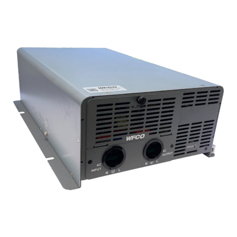
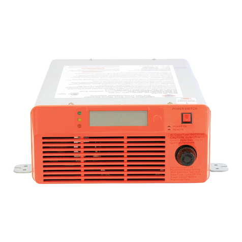
WFCO WF-5300 Series User manual

WF-5300 SERIES
PURE SINE WAVE INVERTER
WF-5318 & WF-5320
Product Manual

TABLE OF CONTENTS
SAFETY INFORMATION.....................................................................................................................1
FEATURES AND APPLICATIONS……...............................................................................................2
OPERATION
Control/Display Panel.........................................................................................................................3
Load Considerations..........................................................................................................................4
Inverter Run Time …..........................................................................................................................5
Standby/Backup Operation...............................................................................................................5
Protection Systems…........................................................................................................................6
Maintenance……….….......................................................................................................................7
SPECIFICATIONS
Electrical Performance.......................................................................................................................8
Mechanical Drawings.........................................................................................................................9
INSTALLATION
Installation Precautions....................................................................................................................10
Installation Location.........................................................................................................................11
System Design.................................................................................................................................12
Wire Selection..................................................................................................................................14
Inverter Mounting.............................................................................................................................15
Control Panel Mounting...................................................................................................................16
Ground Connection..........................................................................................................................17
Dc Connections...............................................................................................................................17
Ac Connections...............................................................................................................................19
Control Panel Connection................................................................................................................22
Testing the Inverter...........................................................................................................................23
Test Switch.......................................................................................................................................23
TROUBLESHOOTING
Protect Modes..................................................................................................................................24
No Output........................................................................................................................................24
Incorrect Output...............................................................................................................................24
WARRANTY......................................................................................................................................25
SERVICE..........................................................................................................................................25

SAFETY INFORMATION WF-5300 Series Pure Sine Wave Inverter
Before operating the inverter, familiarize yourself with all safety precautions outlined in this
manual. Installing or testing inverters can present a safety hazard since there can be multiple
sources of high energy.
• Avoid contact with electrical terminals or exposed wiring when the inverter is operational.
• Turning the inverter o does not disconnect the batteries or ac power source. The ac output will
still be active if there is any other power source, such as shore power.
• Before working on an inverter, carefully check that the inverter is NOT connected to any
batteries, and that all wiring is disconnected from any electrical sources, including shore power
and generator inputs.
PRECAUTIONS WHEN WORKING WITH BATTERIES
• Remove personal metal items such as rings, bracelets, necklaces, and watches when working
with a battery. Batteries can produce a short-circuit current high enough to weld a ring or similar
item to metal causing a severe burn.
• Be very careful when working near exposed battery terminals. Do not drop a metal tool on the
battery. The resulting spark or short-circuit on the battery or other electrical part may cause a re
or explosion.
• If battery acid contacts skin or clothing, wash immediately with soap and water. If acid enters an
eye, immediately wash eyes with running cold water for at least 20 minutes and get medical
attention immediately.
• Never smoke or allow a spark or ame in vicinity of a lead-acid battery.
1

FEATURES AND APPLICATIONS
The WF-5300 series inverters convert 12-volt battery power to 115-volt ac power. They are de-
signed with an internal transfer switch that allows the use of shore power or generator power
when available, and if that power stops, the inverter can automatically and immediately start
providing continuous ac power from the battery. The inverter will continue operating as long as
battery power is available, or until an external source of ac power becomes available again; then
it will
automatically switch back. These inverters are designed for RV applications.
FEATURES
The following features make this inverter an ideal choice for applications that need this level of
output power:
• 2 kW or 1.8 kW output power can easily operate most appliances when ac power is otherwise
not available
• User-friendly remote control for easy and convenient operation
• Remote control displays ac and dc voltage, current, and power to allow verication and
optimization of system operation
• Ruggedized design can handle the bumps from being in a vehicle or trailer
• High eciency provides maximum run time from battery power
• Inverter can start if ac input voltage is outside of a safe range to protect appliances
• Inverter will alert and then stop if the battery voltage is out of range to avoid battery damage
• Output is protected from short circuit, overload, and over temperature to ensure safe and
reliable operation
• Input is protected from reverse battery polarity to ensure safe installation
• Ac connections utilize lever connectors to help with quick, safe, and reliable installation
APPLICATIONS
In trailers, vehicles, and similar o-grid power systems, the 5300 series inverters can operate
many types of 120-volt appliances such as:
• Most air conditioners
• Kitchen appliances – refrigerators, coee makers, toasters, blenders, ice makers
• Household items – device chargers, vacuum cleaners, fans, shavers, sewing machines,
uorescent, incandescent, and LED lights.
• Entertainment electronics – televisions, video games, VCRs, stereos, sound equipment, musical
instruments, satellite equipment
• Oce equipment – computers, printers, monitors, scanners, facsimile machines
• Power tools – drills, circular saws, grinders, sanders, buers, weed and hedge trimmers, air
compressors
2

OPERATION
WF-5300 Series Pure Sine Wave Inverter
CONTROL/DISPLAY PANEL
The 5300 series inverters are operated with a control panel that is separate from the main
inverter unit, which is usually installed in an electrical compartment. The control panel is typically
wall mounted and allows convenient operation in or near a living area in a vehicle.
The control panel includes two pushbuttons and
a display (see Figure 1). The top pushbutton (1)
controls the inverter power on/o status. To turn
on the inverter, press the power button for about
1 second. If it is on, and you want to turn it o,
press the power button again for about 1 sec-
ond.
When the inverter is on, the display will show the
operational status of the power system in various
ways. The graphic shows whether external ac
power is present, whether the unit is in standby
mode, whether it is inverting, and the battery
charge level. In addition, if there is an overload or
other type of fault condition, this will be shown
on the display.
The lower SELECT pushbutton (2) changes the
information shown with the numeric readout on
the display. Initially it will show the ac output
voltage in rms volts. Each time the SELECT
button is pressed, the display’s numeric readout
will change as shown in Figure 2.
Figure 1. Control Panel
Figure 2. Display Readout Sequence
1
3

Figure 3 shows a list of common appli-
ances and how much power they typically
use. This is a generic estimate; for a more
exact rating, look for the label on the
appliance, it should indicate the specic
input power rating.
Many loads, especially motor loads, will
have some inrush current – they will take
more than their rated current or power for
a moment when initially started.
Therefore, it is best to turn these high-
er-power devices on rst, and one at a
time, rather than having everything start at
once (which would happen if their power
switches were already on when starting
the
inverter).
This will help prevent an overload condi-
tion when the inverter starts operating.
LOAD CONSIDERATIONS
When starting the inverter, it’s important to consider how it will be loaded, partly because it has
a certain power limit, and partly because the load directly aects how long it can operate from a
given battery source. Electric heating appliances and air conditioners use a lot of power and
probably can operate only one at a time, but smaller devices, such as phone chargers and small
electronic devices typically use very little power and can be easily operated alongside other
devices.
Figure 3. Typical Device Power
4

INVERTER RUN TIME
The amount of time the inverter can operate before the battery is expended depends on the
loads and the battery (or battery bank) capacity. Figure 4 can be helpful to estimate this based
on the battery capacity and load conditions.
In this chart, three types of battery setups with dierent capacities are shown; 30 Ah is typical
for one lead-acid group 27 battery taken down to 50%, 90 Ah is typical for one lithium group 31
battery taken down to 10%, and 180 Ah is typical for two lithium group 31 batteries taken down
to 10%. This can be used as a reference to estimate the relative time available with dierent
battery
capacities. The eciency is about 90% at mid power levels (it will be lower when under 200
watts). The exact run time is:
Run Time in hours = (Battery Capacity in amp-hours) x (12 volts) x (eciency)
(Total Power Draw in watts)
STANDBY/BACKUP OPERATION
If the inverter is started while external ac power is present (from shore power, generator, etc.), or
if external ac power starts while the inverter is operating, then it will go into standby mode. When
in standby, the inverter will be ready to operate if the external ac source stops. If shore power is
disconnected, or if the generator stops, then the inverter will immediately provide output voltage
so that the connected appliances will continue operating uninterrupted. During standby, the
inverter will use idle power, but this should be supplied by your converter/charger without
aecting the battery.
5
Total Load
Power
Watts
Run Time
using 30Ah
of Battery
Run Time
using 90 Ah
of Battery
Run Time
using 180 Ah
of Battery
0 (idle) 20.0 hours 50.0 hours 120.0 hours
100 2.9 hours 8.7 hours 17.5 hours
250 1.3 hours 3.8 hours 7.6 hours
500 39 minutes 1.9 hours 3.9 hours
1000 19 minutes 58 minutes 1.9 hours
1500 13 minutes 38 minutes 1.3 hours
Figure 4. Approximate continuous load run time.
Approximate Continuous Run Time vs. Power Usage From 12-volt Battery

PROTECTION SYSTEMS
The WF-5318 and WF-5320 inverters include protection features that ensure safe operation and
recovery from a wide range of fault conditions.
When a protection feature is activated, the inverter will sound an audible alarm to indicate that
output power has stopped. In the case of the battery voltage approaching its limit, the alarm will
provide a warning sound before the power actually stops. Fault alarms may continue for up to
one minute.
Overload
If too much current or too much power is drawn by the load on the inverter, it will stop. The
design includes considerable margin for providing momentary inrush current to start motors
or other dicult loads. But if the overload continues for a longer time (which depends on the
amount of overload), then the unit will stop to prevent equipment damage. The remedy is to
reduce the load on the inverter, so that it can operate. After 40 seconds, the inverter will
automatically attempt to restart. You can also turn the inverter o and on to restart it sooner.
Under or Over Voltage at Input
If the battery input voltage drops below 11 volts, the alarm will sound to warn of a low battery
voltage. If the voltage drops below 10 volts, then the inverter will stop.
If the battery input voltage is above 15 volts, the alarm will sound to warn of a high battery
voltage. The inverter will stop if the input is above 16 volts.
Over Temperature
An excessively high temperature inside the inverter will cause the inverter to stop. When the unit
cools down, it will restart once. If overheating persists after that, it will remain o. If it is cool
enough, manually cycling the power switch can restart operation.
Short Circuit
A short circuit on the ac output – that is, if the line and neutral output are accidentally
connected together – will cause the inverter to stop. After the problem is corrected, the inverter
can be restarted.
Dc Reverse Polarity
Be very careful when connecting a battery to the dc system. It is usually very critical that the
polarity is correct because some equipment may be permanently damaged if the polarity is
6

reversed. However, the WF-5318 and WF-5320 will survive that; the inverter simply will not
operate. When the polarity is corrected, the inverter will function normally.
Ac Circuit Breaker
The ac output circuit is protected by a 30-amp auto-resettable circuit breaker. If excessive
current is drawn at the output (including when in pass-through mode), the breaker may open
the circuit. If that happens, the circuit breaker will automatically reset within one minute.
MAINTENANCE
To ensure years of reliable performance, it’s a good idea to periodically check the following:
• Make sure the inverter is clean. Turn o all sources of ac power including the inverter, and
then clean the exterior of the inverter with a slightly-damp cloth to prevent accumulation of dust
and dirt.
• Make sure the vents and fan openings are not clogged.
• Inspect the wiring and terminations; make sure the connections are tight and all wiring and
insulation is in good condition. Check for any discoloration of conductors or insulation, melted
plastic, or other sign of heat. Evidence of excessive heat usually indicates a loose or corroded
connection; this needs to be corrected immediately.
7

MODEL WF-5318 WF-5320
Inverter
Waveform
Output Voltage
Output Current 15.7 A 17.4 A
Continuous Output Power 1800 W 2000 W
Surge Power, 2 sec. 3600 W 4000 W
Output Frequency
Output THD, resistive load
Input Voltage Range
Input Current (no load), 12 Vdc input
Input Current (full load), 12 Vdc input 180 A 200 A
Peak Efficiency
Transfer Switch
Transfer Time
Ac Pass-Through Rating
Switch to Shore Power
Switch to Inverter
Remote Control Panel
Control Functions
Display Functions
Protection
Output Circuit Breaker
Overload
Short Circuit
Over Temperature
Battery Reverse Polarity
Safety Listing
Connectors
Dc Input
Ac Input and Output
Ground
Remote Control Panel Connector Type
Remote Control Panel Cable Length 20 ft (6 m) 30 ft (9 m)
Mechanical/Environment
Dimensions (LxWxH)
Weight
Cooling
Unit Installation
Operating Environment
14 °F to 104 °F and 20% to 90% RH Non-condensing
SPECIFICATIONS
Screw Clamp for up to 2 AWG wire
12.3 (13.6) x 9.5 (10.7) x 4 inches
11.5 lb
Allow at least 2 cubic feet of air around unit with 3 inches
of space at each end for air flow.
Bottom or side panel facing downward
Auto shutdown
Auto shutdown, one auto recovery during operation
No damage
UL 458
Bolts for Ring Lugs Size M8/1.25, 13mm hex nuts
Lever connectors for up to 10 AWG wire
Sine Wave
115 V ac ±3%
60 Hz ±0.3 Hz
< 4%
10.0 - 16.0 V dc
< 90 Vac or > 140 Vac
Ac Output Voltage, Current, Power
6P6C (RJ-25)
< 1.6 amps
> 90%
Ac Input/Standby/Invert Status
Protect/Fault Diagnostics
30 A
Auto shutdown, auto recovery
< 20 ms
24.8 amps
> 80 Vac or < 130 Vac
Dc Input Voltage, Current, Power
Inverter Start/Stop
Display Select
8

Figure 5. Control Panel Dimen-
MECHANICAL DRAWINGS
Figure 6. Inverter Dimensions
9

INSTALLATION: WF-5300 Series Pure Sine Wave Inverter
CAUTION!
The electrical installation must conform to the local electrical codes and should be carried out by
a certied technician. The safe installation of an inverter requires some knowledge and skill. Only
a qualied technician should perform this electrical work.
Turning the inverter o does not disconnect the batteries or ac power source. Therefore, the ac
output will still be active if there is any other power source, such as shore power, generator, etc.
Shock Hazard. Before proceeding further, carefully check that the inverter is NOT connected to
any batteries, and that all wiring is disconnected from any electrical sources such as shore
power,
generator, etc. Do not connect the output terminals of the inverter to an incoming AC source.
INSTALLATION PRECAUTIONS
• Always turn o or disconnect all power sources (ac and dc) before working on any of the wir-
ing. Do not restore power until the wiring is complete and fully inspected.
• Be very careful about polarity and correct wiring terminations. Be sure to check the wire colors
and make sure they are connected correctly. If there is any doubt about wire colors or
connections, check the connections at the other end of the wire and make sure it is connected
as expected. For dc circuits, the wiring polarity is critical to avoid damage. With ac circuits, the
line, neutral, and ground must each be connected to its intended terminal to avoid a very
dangerous result.
• Do not expose the Inverter to rain, snow, spray, bilge, or dust. To reduce risk of hazard, do not
cover or obstruct the ventilation openings. To avoid overheating, do not install the inverter in a
zero-clearance compartment.
• To avoid the risk of re and electric shock, please make sure that existing wiring is in good
electrical condition; and that wire size is not undersized. Do not operate the Inverter with
damaged or substandard wiring.
• This equipment contains components which can produce arcs or sparks.
• To prevent re or explosion do not install in compartments containing vented batteries or
ammable materials or in locations which require ignition protected equipment. This includes
any space containing gasoline-powered machinery, fuel tanks, joints, ttings, or other
connection between components of the fuel system.
• Separate over-current protection for the AC output circuit shall be provided as necessary.
10
WARNING
WARNING

Operating the inverter without a proper ground connection may cause an electrical safety haz-
ard. An 8 AWG or larger ground wire is required to connect the inverter ground to the chassis.
INSTALLATION GUIDELINES
• Please determine the remote control panel cable route throughout the vehicle, both to and
from the inverter before connecting any wires.
• Always check for existing electrical, plumbing, or other areas of potential damage before
drilling or cutting into walls to mount the control panel.
• Make sure all wires have a smooth bend radius and do not become kinked. The allowable
bend radius depends on the type of cable and wire gauge.
• Please ensure that all conductors passing through walls, bulkheads, or other structural
members are protected. This minimizes insulation damage such as chang, which can be
caused by vibration or constant rubbing when installing in a vehicle.
INSTALLATION LOCATION
The power inverter should be installed in a location that meets the following requirements:
• Dry – Do not allow water to drip or splash on the inverter.
• Cool – Ambient air temperature should be between -20°C and 40°C, but the cooler the better.
• Safety – Do not install inverter with lead-acid batteries in the compartment, or other areas
near ammable fumes such as fuel storage areas or engine compartments.
• Ventilated – Allow at least one cubic foot of clearance around the Inverter for air ow. Ensure
the vents on the ends and top of the unit are not obstructed.
• Dust-free – Do not install the Inverter in environments where dust, wood particles, or other
lings or shavings are present. The dust can be pulled into the unit when the cooling fan is in
operation.
• Close to batteries – Avoid excessive cable lengths but do not install the inverter in the same
compartment as lead-acid batteries.
• Do not mount the inverter where it is exposed to the gases produced by a lead-acid battery.
These gases are very corrosive and prolonged exposure will damage the inverter.
• Use the recommended wire lengths and sizes in accordance with this manual and the relevant
electrical codes.
11
WARNING

SYSTEM DESIGN
Before installing an inverter system, it’s important to plan the design and procure the necessary
tools and materials. In addition to the inverter, batteries, appropriate wire, wire terminals, fuses
or circuit breakers, and possibly other accessories will be needed.
Figure 7. Typical Installation for RV.
12

Ac Power Distribution Panel
Branch rated over current protection for the AC output circuit is to be provided at the time of
installation.
A branch circuit at the ac power distribution panel can be used to supply the ac input to the
inverter for bypass operation. This circuit should use a 15-amp or 20-amp circuit breaker. The ac
output from the inverter can feed a separate section in the same panel, such as the WF-7923-S
or WF-7925-S, to supply multiple circuits that can be powered by the inverter. Alternatively, a
second panel can be used for the inverter-powered circuit distribution, if more than one circuit is
to be powered by the inverter. Refer to Figure 6 for a wiring example.
The wire gauge needed for the ac wiring should follow NEC requirements for ampacity and circuit
protection. Strain relief should be provided near the inverter for the ac cables.
MANUFACTURER MODEL NUMBER
Hubbell GFRST20W
Leviton GFWR2-W
Cooper Wiring Devices TRSGF20
Pass & Seymour, Inc. BGFCI-20
Guangzhou Bosslyn BGFCI-20
Figure 8. Allowable GFCI Devices
13

WIRE SELECTION
The wiring in an electrical system is important both for safety and for proper operation. The
wiring needs to conform to the NEC (National Electrical Code) in the U.S.A. and any other
regional or local codes or electrical regulations. If there is uncertainty about this, be sure to
check the codes that apply to your installation.
The main considerations are:
• Wire Gauge for Ampacity
To prevent a re, the wire must be capable of handling the maximum possible current without
overheating.
• Wire Gauge for Voltage Drop
The wire needs to have a low enough resistance to avoid excessive voltage drop across its
entire length.
• Stranded or Solid Conductors
Solid copper wire conductors can be used if the wire is not going to move; for permanent
ac wiring this is okay. For the battery cables and dc wiring, stranded conductors are usually
preferable due to exibility and ease of installation with the typically heavier gauge wire that is
used. In some cases, stranded may be needed if the wires are bundled.
• Insulation Rating
The wire’s insulation must have the correct type, voltage rating, and temperature rating for the
application.
Circuit Protection
Each electrical wire in a vehicle or trailer must be protected by a fuse or circuit breaker that will
open before the wire can overheat. The current rating of the fuse or circuit breaker should not
be higher than the ampacity of the wire.
Ground
The inverter needs to be grounded to the vehicle chassis. The electrical code requires that an 8
AWG wire is used for this, since it needs to be able to open the main circuit breaker in case of
a short circuit to ground. See the Inverter Ground Connection section on page 24.
14

INVERTER LOCATION AND MOUNTING
In addition to being as close to the battery or batteries as possible, with lead-acid batteries
being in a separately ventilated compartment, the WF-5318 and WF-5320 can be mounted to
a horizontal deck or vertical wall. Mounting anges are provided on each side and they can
accommodate ¼” bolts for mounting to a deck or wall. Vent openings (the ends or top) should
not be oriented downward. See Figure 8 for the mounting orientation.
In addition, for proper air cooling, there should be at least 2 cubic feet of air around the inverter
and at least three inches of space at each end.
Figure 9. Inverter wall mounting orientation. Horizontal is okay, vertical is
not.
CORRECT
15
CORRECT INCORRECT

CONTROL PANEL LOCATION AND MOUNTING
The control panel is designed to be mounted in a wall; it can be positioned in any convenient
location that can be reached from the inverter by its cable. The included cable is 20 feet (6 m)
or 30 feet (9 m) long, depending on the model. The cutout for mounting the control panel can
be made with a 2-7/8” diameter hole saw. The panel is secured to the wall with four #10 or
#12 screws. See Figure 6 for control panel dimensions and Figure 9 for the mounting cutout
pattern
Figure 10. Panel Mounting Pattern
16

DC WIRING CONNECTIONS
Battery Cables
During high power operation, the battery cables to the inverter will see a very high current which
will cause some voltage drop. This voltage drop represents power loss, and if it’s too high it can
aect the surge power capability of the inverter.
The best solution is to position the inverter close to the batteries (as previously stated, if
lead-acid batteries are used, they need to be in a separate compartment). If they are within a
few feet, then cables with suitable ampacity will work well, with low voltage drop (less than 2%).
But if the
inverter is more distant from the batteries, then a larger gauge wire may be needed to prevent
excessive voltage drop. Use only high-quality copper wire.
The positive battery connection requires a fuse or circuit breaker that is within 18 inches of the
battery or its cable entrance to the vehicle. The fuse rating should conform with safety stan-
dards and be determined according to the specied wire ampacity. Suggested wiring and pro-
tection for the WF-5318 and WF-5320 is shown in Figure 11.
ITEM WF-5318 WF-5320
Rated Continuous Current 180 200
Minimum Safety Ground Wire Size 8 AWG 8 AWG
Minimum Dc Wire Size 2/0 2/0
90 degrees C insulation 105 degrees C insulation
Maximum Dc Fuse Size 195 amps 225 amps
Figure 11. Dc wiring suggestion for WF-5318 and WF-5320.
The cables from the battery and fuse are connected to the positive and negative bolt
terminals on the inverter. Be sure to observe correct polarity; the red terminal is positive (12
volts) and the black terminal is negative. The bolt terminals should be tightened to 6 ft-lbs or
8.1 Nm
maximum torque.
Rubber covers are provided for the terminations; slip these over the cable ends before
attaching the cables, then after the connections are secured, the cover can be moved over the
terminals for insulation and protection.
17

Notes:
• Make sure all the connections are tight. Loose connections can overheat and result in a
potential hazard.
• The installation of a fuse must be on the positive cable. Failure to place a fuse on this cable
running between the inverter and battery creates a safety hazard.
• Do not place anything between the battery cable lug and the terminal surface. If desired, a
at washer can be used on top of the terminal to protect it as the nut is tightened.
• During the rst installation, a small spark is a normal phenomenon when the battery is
connected because the internal capacitors will charge.
18
This manual suits for next models
2
Table of contents
Other WFCO Inverter manuals
Popular Inverter manuals by other brands

Cypress
Cypress CPA-1 user manual

Winco
Winco W6010DI Installation and operator's manual

Heat IQ
Heat IQ EcoLogic IQ AS7V1Ph Operation, installation & maintenance instructions

Westinghouse
Westinghouse 2400i instruction manual

Miller
Miller Bobcat 250 Application guide

SolaX Power
SolaX Power X3-ULTRA installation manual

SamplexPower
SamplexPower PST-1500-12 owner's manual

Sermatec
Sermatec SMT-10K-TL-TH Basic Introduction

SOLARMG
SOLARMG SG-OST50-60T user manual

Trace Engineering
Trace Engineering DR Series owner's manual

socomec
socomec SUNSYS - B10 Installation and operation manual

MULTIQUIP
MULTIQUIP WHISPERWELD SGW-250SS Parts and operation manual