Zlpower IG500-12-C User manual

USERMANUAL

General Precautions
1. Before using thisInverter, read allinstructionsand cautionarymarkings
on :
(1)Inverter(2)the batteries(3)thismanual
2. CAUTION --To reduce riskofinjury, charge onlylead-acid rechargeable
batteries. Othertypesofbatteriesmaycausedamage and injury.
3. Do not exposeInverterto rain,snoworliquidsofanytype. Inverteris
designed forindoor.
4. Do not disassemble Inverter.Take it to a qualified service centerwhen
service orrepairisrequired.
5. WARNING: Provide ventilation to outdoors fromthe batterycompartment.
The batteryenclosure should be designed to prevent accumulation and
concentration ofhydrogengasat the top ofthe compartment.
6. NEVER charge a frozen battery.
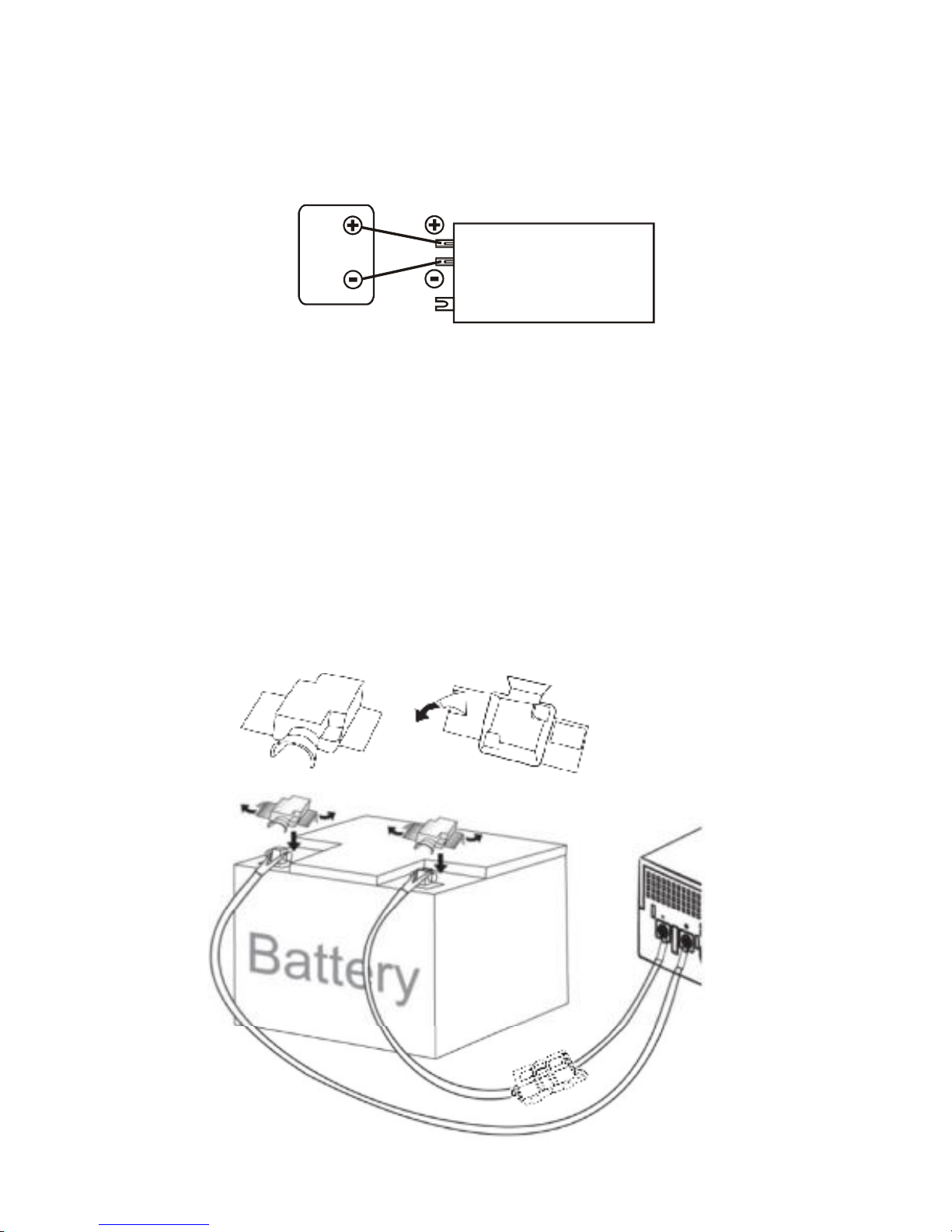
7. Input/outputACwiring must be no less than 18AWGgaugecopperwire
and rated for75oC orhigher. Batterycablesmust be rated for75oCor
higherand shouldbe no less than 10AWGgauge. The innerdiameterof
the copperring terminalwhich isused toconnect batterycablesto
InverterDC terminalsshould be no less than 6mm.
8. Be extracautiouswhen working with metaltoolsaround batteries.
Short-circuiting the batteriescould cause anexplosion.
9. Read the batterymanufacturer sinstallation and maintenanceinstructions
priortooperating.
Personnel Precautions
1. Have plentyoffresh waterand soap nearbyin case batteryacidcontacts
skin, clothing, oreyes.
2. Avoid touching eyeswhileworking nearbatteries.
3. NEVER smoke orallowasparkorflame in vicinityofa battery.
4. Remove personalmetalitemssuch asrings, bracelets, necklaces, and
watcheswhen working with batteries.Batteriescanproduce a short-circuit
current high enough to make metalmelt, and couldcause severeburns.
5. Ifa remote orautomaticgeneratorstart systemisused, disablethe
automaticstarting circuitordisconnect thegeneratortoprevent accident
during servicing.

Introduction
This Inverterisa DC-to-ACinverterwithauto line-to-batterytransferand
integrated chargingsystem, serving asan extended run UPS,a standalone
powersourceoran automotive inverter.
InvertersuppliespowerfromAC powerand DC source. When AC cableis
connected to awallsocket, utilitypowergoesto connected equipment(s)
and/orchargesthe batteryset via charging system. In UPSmode, Inverter
automaticallyconvert batteryenergyintoACpowerforbacking up the
connected devices.
Features:
lAutomaticline-to-batteryswitchover
lSelectable Inputvoltage ranges
lHighefficient DC-to-ACconversion, minimizingenergyloss
lRackTowerdesignforflexibleplacement
lBuilt-in enhanced charger
lIntelligent 2-stage chargercontrolforefficient chargingand preventing
overcharge
lProvidesoverload protection
lAutorestartwhileAC recovery
lMulti-function LCDdisplayand buzzeralarms

Operation
FrontPanel Controlsand LCD display
Shown below arethe controlsand indicatorlightson the front ofInverter.
Figure 1FrontPanel
PowerOn/Off
Poweron/offbutton isshown asabove. OnceInverterhasbeen properly
installed and batteriesare connected, press thisbutton and Inverterwillturn
on automatically,and worksin mainsmode orinvertermode according to
input AC sourcesstatus.When press thisbutton again, Inverterwillturnoff
automatically.
LCD DISPLAY
1. LCD Back-Light
The LCD will alwaysturnson when inverterworks, including in off
charging mode and fault mode.
2. When LCD startsto work, itwilldisplayallinformation for3 seconds.
POWER ON/OFF LCD display

3. When inAC mode, itwilldisplayasbelow.
4. When in Batterymode, it will displayasbelow.And the markwill
flickerevery1second.
5. When in offcharging mode,itwilldisplayasbelow. Batterycapacity
displayssame asbelowitem5.
6. When in charging mode, the batterysegmentswilldisplayasbelow.
Remark: Offmodechargingissame.
7. Loadleveldefinition(the tolerance is 10%rating power):
Whenover load, themarkwill flicker every1second.
status Batteryvoltage
12V 24V 1 2 3 4
CC/CV
Bat>13V Bat>26.0V Solid on Solid on Solid on Flashing
Bat>12.5V Bat>25.0V Solid on Solid on Flashing1
Flashing2
Bat>12.0V Bat>24.0V Solid on Flashing1
Flashing2
Flashing3
Bat<=12.0V Bat<=24.0V Flashing1 Flashing2
Flashing3
Flashing4
Floating
Anybatteryvoltage Solid on Solid on Solid on Solid on

8. Batterycapacitydefinitionin invertermode 24Vbatteryindication isas
twice as12Vbattery,the tolerance is 0.2V ):
Whenbatterylow, themarkwill flicker every1second.
9. Troubleshooting.
Wheninfault mode, it will displayasbelow.
Fault codetable
Faultmode Linemode Batterymode
FaultcodeOutputstatus
Overload1(Vout<195V) / / 0 Off
OutputvoltageRMS low / / 2 Off
Shortcircuit / / 3 Off
Fanlocked 4 On 4 Off
Batteryvoltagehigh 5 On 5 Off
Overload2(Vout ≧195V;
Pout﹥80%ratedhalf-waveload) 6 On 6 Off
Overload3(Whenunitpowers
half-waveload, differencevalue
betweenpeakvoltageofpositive
halfwaveform andnegativehalf
waveform﹥150Vandlastout20
cycles)
/ / 7 Off
OutputvoltageRMS high / / 8 Off
Peakoutputvoltagehigh / / 8 Off
Ifanyabnormal situationsoccur that arenotlistedabove, pleasecall service
people immediately.

Back Panel Description
Shown below arethe componentson the backofInverter.
Figure 2BackPanel
DC Input Connector(BatteryTerminal)
②Input Fuse
③AC Input Receptacle
④Output Receptacle(s)
⑤Input Voltage RangeSelector: (Input voltage rangeisdefined in
specification chapter,andoutputvoltage isthesame asinput voltage in
mainsmode)
A.Select Narrow’setting forgeneralelectricalappliance: If you select
thismode, theInverteroperatingvoltageinLine mode is within
170~280Vac(90~145Vac) with the same output voltage. The line
sensitivityishigher. Hence, you can connect the computersystemsor
otherprecision home equipment whenyou select thismode.
B.Select Wide’setting tosaveenergy: If you select thismode, the
Inverteroperating voltage in Line mode willbe extended within
90~280Vac(50~145Vac) with the same output voltage.The Inverteris
with the lowerline sensitivity.Moreover,there will be taking a long transfer
○
2

time when the InvertertransferfromNormalmode to Batterymode during
powerfailure. Hence, you can connect the home equipments, such as
light bulb, fan, fluorescent tube, orTVwhen youselectthismode.
Caution!! If you select the Wide’mode and connectthe computerto the
output ofInverter, the computermayreboot iftheinput voltage istoo low
to beaccepted. In addition,the long transfertime willhappenwhen power
failure makesthe computerreboot.
BatteryConnection
Step1- Pinch the bottomof DC inputcoverandOpenit. See Figure4.
Step2- Following batterypolarityguide located nearbattery
terminal!Place the batterycable ring terminalover
Inverter sbatteryterminal. Tighten the M5 nut. Do not
placeanythingbetween the flat part ofbatteryterminal
and the batterycable ringterminal, oroverheating may
occur.
Caution! DONOT place anything between
batterycable ring terminalsand battery
terminals.The terminalstud isnot designed
to carrycurrent.ApplyAnti-oxidant paste to
terminalsafterterminalshavebeen torqued.
Figure 4BatteryCableConnectiontoInverex

Step3- Connect batterycablestoyourbatteries
lSingle batteryconnection: When using a singlebattery, itsvoltage must
be equaltothevoltage ofInverterNominalInputVoltage (see specs)
12VDC
lForthe useroperation safety,we stronglyrecommend that you should
isolate the batteryterminalsbeforeyou start to operate the unit. Please
referto belowinstruction forfurtherinformation. If you parallelmore
batteriesto extend the backup time, please make sure that you already
use tapesto isolate the restbatteryterminalsbeforeyou start to operate
the unit.
lNote: When connect the inverterand battery,need to string into the fuse
between inverterand battery.

lSeriesbatteryconnection: When using multiplebatteriesin series, all
batteriesmust be equalinvoltage and amp hourcapacity,and the sumof
theirvoltagesmust be equalto the voltage ofInverterNominalInput
Voltage (see specs)
24VDC
lParallelbatteryconnection:When using multiplebatteriesin parallel,each
batterysvoltage must be equalto the voltage ofInverterNominalInput
Voltage (see specs)
AC Connection
Before havingAC connection, match the powerrequirementsofconnected
deviceswith the poweroutput ofInverterto avoidoverload. Consult a
qualifiedelectrician, and followlocalcodeforthe properwire sizes,
connectors and conduit requirements.

Specification
MODEL IG500-12-C
IG1000-12-C
IG2000-24-C IG 1000-24-C
CAPACITYVA/W 500VA/300W 1000VA/600W 2000VA/1200W 1000VA/600W
INPUT NominalVoltage 110/120VAC or 220/230/240VAC
Voltage Range 90-145VAC or 170-280VAC (NarrowRange)
50-145VAC or 90-280VAC (WideRange)
OUTPUT Voltage 120VAC or 230VAC
Voltage Regulation (Batt. Mode)
+10%/ -18%
Frequency 50Hz or 60Hz
Frequency Regulation (Batt.
Mode) +/-0.1Hz
OutputWaveform Modified Sine-wave
BATTERY&
CHARGER Charger Current 10Amp+/-1Amp
10 Amp+/-1Amp
10Amp+/-1Amp
10A+/-1Amp
DC Voltage 12V+/-0.2V 12V+/-0.2V 24V+/-0.4V 24V+/-0.4V
Overcharge Protection 14.5V+/-0.3Vchargerstops and
fault 29V+/-0.6Vcharger stops and
fault
TRANSFER
TIME Typical 10-20ms typical(narrowrange); 40msmax(wide range)
EFFICIENCY AC toAC >95%
DC toAC >80%
INDICATOR AC Mode Green lighting
Battery Mode Yellowlighting
Battery Charging Mode Green flashing every 2seconds
Overload Red flashing every 0.5second
Fault Red lighting
AUDIBLE
ALARM LowBattery at Battery Mode Sounding every 2seconds
Overload Sounding every 0.5second
Fault Continously sounding
PROTECTION Full Protection Discharge, overcharge, and overload protection
PHYSICAL Dimension (DxWxH)mm 224 X255 X80
NetWeight (kgs) 1.7 2.1 2.3 2.1
ENVIRONMENT
OperatingEnvironment 0- 40°C, 0-90 %relativehumidity (non-condensing)
NoiseLevel Less than 55dB
*Product specificationsaresubject to change without furthernotice.
Version:00
614-00005-00
This manual suits for next models
3
Table of contents
Other Zlpower Inverter manuals
Popular Inverter manuals by other brands

DASS Tech
DASS Tech SOLEAF DSP-3320i-ODS Manual for use and installation

Visicomm
Visicomm 4KSS60400 user manual

Growatt
Growatt MID 17-33KTL3-X Installation & operation manual

Leroy-Somer
Leroy-Somer POWERDRIVE MD2CS Installation and Maintenance

Mastervolt
Mastervolt Whisper 6 user manual

FujiFilm
FujiFilm FRENIC-Mini instruction manual

Atlas Copco
Atlas Copco QAS366 Gd USA instruction manual

CPS
CPS SCA23 Installation and operation manual

Stanley
Stanley PC500 instruction manual

Toshiba
Toshiba HX7+ ASD Installation & operation manual

Solectria Renewables
Solectria Renewables PVI 15KW Installation and operation manual

LG
LG RESU16H Prime installation manual