Sourcetronic MD-5075 Series User manual

3
MD-5075x
5kV Insulation tester
User’s Guide
© 2009 Sourcetronic. All rights reserved.

4
Safety warnings
•
Before to use this instrument the User’s guide and Safety warnings must
be read and understood.
•
Safety procedures and rules for working near high voltage energized
systems must be observed during the use of this equipment. The
generated voltages may be dangerous.
•
Do not connect or disconnect the test leads during the measurement.
•
Be careful not to make short-circuit between the terminals while a
measurement is running, because it could be dangerous for the operator.
•
Be sure that there are not any voltage difference between the points to
which the megohmmeter will be connected to, neither between them and
ground.
•
The panel, terminals and connectors of the equipment must stay dry and
clean.
This equipment should be used only by a trained and
competent person, strictly applying suitable safety rules.
Used symbols
Caution, risk of electric shock.
Caution, refer to User Guide.
Equipment complies with current EU Directives.
Battery
Printer
Capacitance
Backlight

5
Index
Used symbols_______________________________________________________4
1. Description _______________________________________________________6
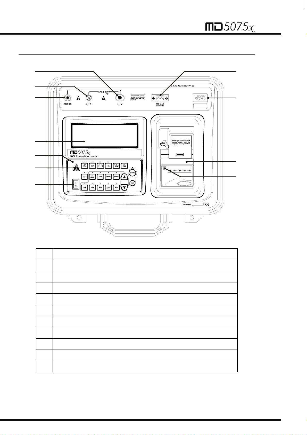
2. Panel control functions______________________________________________7
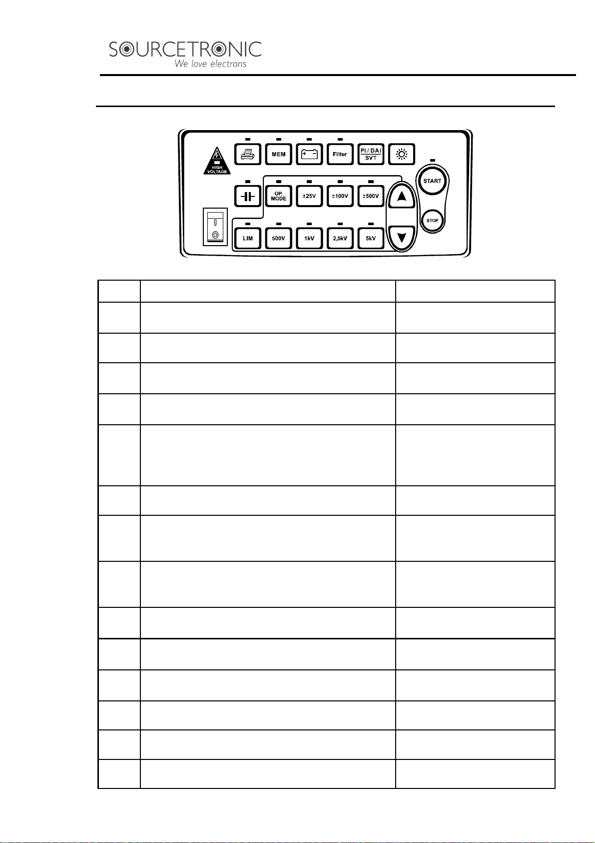
3. Keyboard ________________________________________________________8
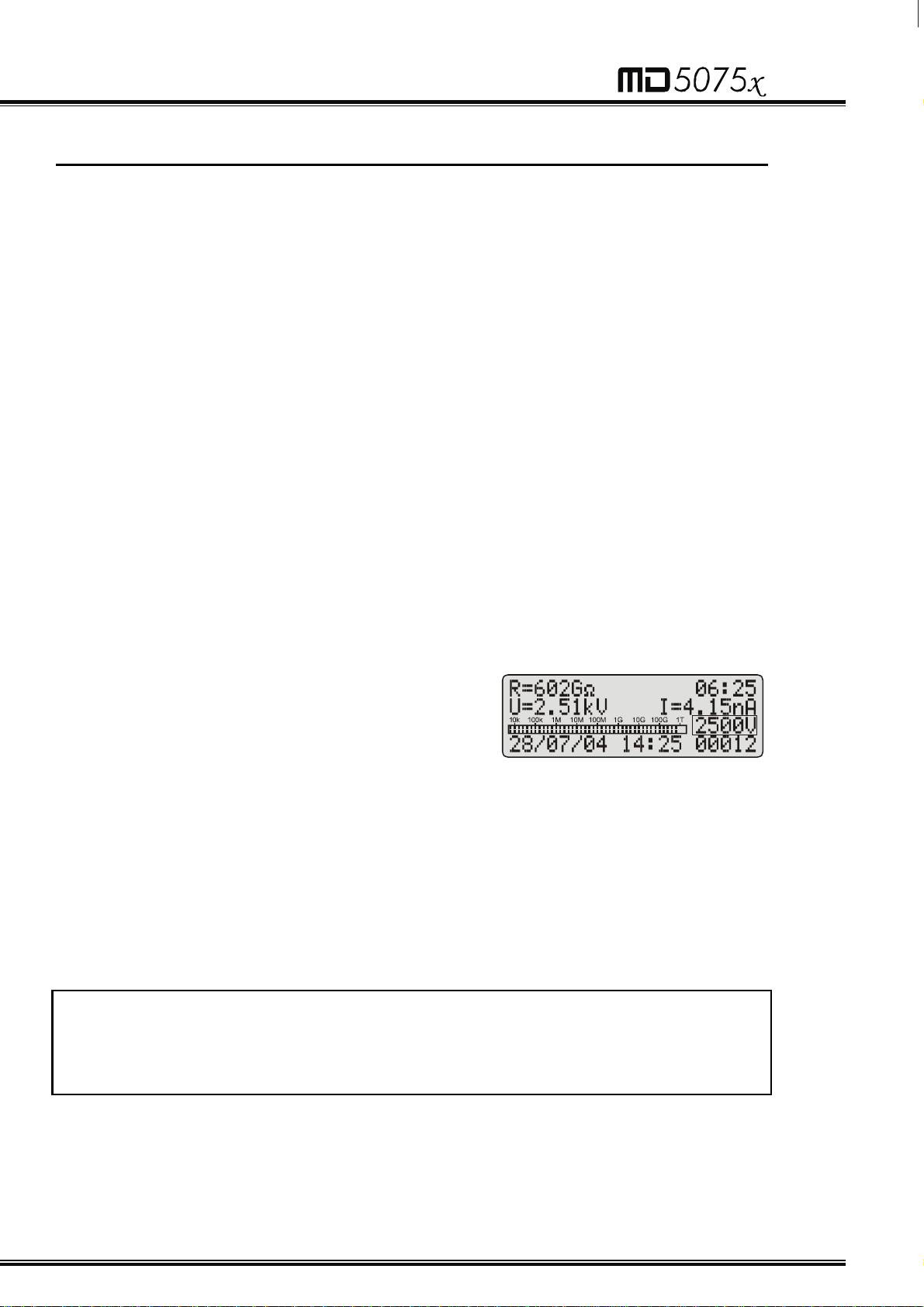
4. Display __________________________________________________________9
5. Charging Battery _________________________________________________10
6. Connecting the MD-5075x __________________________________________10
7. Use of “Guard” (G) terminal _________________________________________12
8. Setting tests _____________________________________________________12
8.1. Test voltage definition __________________________________________13
8.2. Selection of the operation mode __________________________________13
8.2.1. Normal mode _____________________________________________13
8.2.2. “TIMER” Mode ____________________________________________13
8.2.3. SVT Mode (step voltage tests)________________________________14
8.2.4. “Pass / Fail” Test mode _____________________________________14
9. How to perform tests ______________________________________________15
9.1. Measurement of the Polarization Index (PI) _________________________16
9.2. Measurement of the Dielectric Absorption Index (DAI) _________________16
10. Other functions__________________________________________________17
10.1.1. Backlight________________________________________________17
10.1.2. Filter ___________________________________________________17
10.1.3. True RMS AC/DC Voltmeter_________________________________17
10.1.4. Leakage current measurement_______________________________17
10.1.5. Capacitance Measurement__________________________________18
10.1.6. Memory ________________________________________________18
10.1.7. Battery status check_______________________________________18
10.1.8. Auto power-off ___________________________________________19
11. Data Transfer ___________________________________________________19
12. MegaLogg2 Software _____________________________________________20
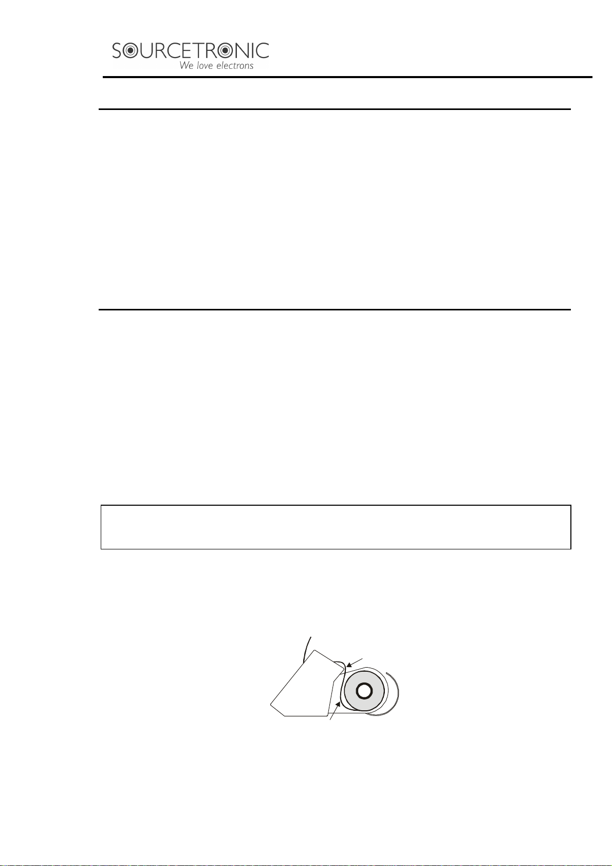
13. Printer_________________________________________________________20
14. Cleaning_______________________________________________________21
15. Technical specifications ___________________________________________22
16. Application note 32_______________________________________________24
17. Warranty_______________________________________________________26

6
1. Description
The digital insulation tester model MD-5075x is at the cutting edge of
SOURCETRONIC insulation analyzer equipment and it is one of the more
complete and sophisticated of the international market. It uses an efficient
well experienced technology, which provides safe, reliable and accurate
measurements of insulation resistances up to 5TΩ
ΩΩ
Ω, with 4 pre-selected test
voltages, 500V -1kV –2.5kV -5kV. Other test voltages may be selected in
steps of 25V, 100V, or 500V.
A microprocessor controls the equipment, making the operation easier and
enabling the incorporation of advanced features such as: Auto-range
selection, Memory enabling storing up to 4000 readings, AC/DC voltmeter,
Polarization and Dielectric absorption index automatic measurement,
Measurement of Leakage Current and Capacitance, “TIMER” to program
resistance test time, “Limit” allowing making test type "Pass / Fail" with
programmable limit. Step Voltage Test, Built-in Printer, Real Time Clock and
Calendar for measurement identification. Built-in chronometer, indicating
elapsed time, in minutes and seconds, since the test started
RS-232 interface enables communication of the equipment with a computer
to transmit registered data. MegaLogg2 software analyzes the results and
shows through drawings and tables, automatically generating the test
protocol. The built-in printer records values on paper every each 15
seconds, as a measurement taken document.
Owing to its constructive features, this instrument is strong delivering an
excellent performance both with laboratory and field works, under hard
environment conditions, typical from tropical regions.

7
2. Panel control functions
Voltage output terminal (-V)
Zero reference terminal (+R)
Guard (G) Terminal
Display
Keyboard
High Voltage led
On / Off key
RS-232 communication port
Power supply input
Printer
Paper feed control

8
3. Keyboard
Key Function LED
Α
Turns the printer on/off Indicates that the printer is
turned on.
Β
Hold – Freeze the last reading on the display The Hold function is on
Χ
Battery – exhibits the battery load status on
the display Indicates that the battery
charger is on
∆
Filter – Activates the filter that minimizes the
interferences of the external noise Indicates that the filter is on
Ε
Shows the calculated value on the display as
a result of a Step Voltage Test (SVT),
Polarization Index (PI) and Dialectic
Absorption Index (DAI)
–
Φ
Backlight – activates the display light –
Γ
Capacitance – exhibit the capacitance value Indicates that the
capacitance value is being
exhibited
Η
Activated enables the programming of the
Operation Mode (Normal, SVT or with TIMER
of selectable time)
Indicates that the selection
of the Operation Mode is
enabled
Ι
Activated, enables programming of 25V step
tests voltages 25V steps activated
ϑ
Activated, enables programming of 100V
step tests voltages 100V steps activated
Κ
Activated, enables programming of 500V
step tests voltages 500V steps activated
Μ
Selection of 500V test voltage Indicates 500V selected
Ν
Selection of 1kV test voltage Indicates 1kV selected
Ο
Selection of 2.5kV test voltage Indicates 2.5kV selected

9
Π
Selection of 5kV test voltage Indicates 5kV selected
Θ
Ρ
These keys (decrease or increase) enable
the selection of the value that is being
programmed.
–
Λ
Activates/ enables programming of the limit
for the “Pass / Fail” test Indicates when the
measured resistance is
lower than programmed
limit
Σ
Start – Start test Indicates that the test is
being executed
Υ
Stop – End of test –
4. Display
Measurement results in the corresponding measuring unit, elapsed time
since the measurement started, selected test voltage, analogue indication
by means of a bar-graph and several messages to the operator are
displayed on alphanumeric LCD.
Applied voltage
Measured result
Bar-graph
Data & Time
Elapsed time
Current
Selected voltage
Test Nº.

10
5. Charging Battery
The MD-5075x uses a rechargeable Ni-MH 12V – 3Ah battery. This battery
should be recycled at the end of its service life or placed in an appropriate
site, in order to protect the environment.
Charging Procedure:
Test if the MD-5075x is off and connect it to the mains. The charging
indicator (led over key
Χ
) will turn on red and will remain that way until the
battery is totally charged. Then the light will remain green and keep in that
way until the MD-5075x is disconnected of the mains. If the equipment is
turned on, the charging procedure will be momentarily interrupted, with the
mains supplying the operation of the MD-5075x till it is again turned off.
Note: the battery losses part of its charge slowly, even when it is not under
use. Before using this device, or after not using it for a long time, the battery
may need to be recharged.
6. Connecting the MD-5075x
ATTENTION: Bearing in mind operator’s safe working conditions,
procedures detailed below should be carried out with the device being in
OFF position.
Please, do check there is no difference of potential voltages between the
points where the MD-5075x shall be connected to. Please, check the same
between those points and the ground. Connect the red cable security
terminal to the megohmmeter (-V) output terminal, the BNC terminal of the
black cable to the zero reference (+R) terminal and the “alligator” terminals
to the element to be measured as indicated in the figure detailed below.

11
SAFETY
TERMINAL
BLACK BNC
CONNECTOR
ELEMENT TO BE MEASURED
BLACK
TERMINAL
RED TERMINAL
The terminals in the picture are merely illustrative, so there can be differences between them and
the ones which really come with the equipment.
Observation: At the time of the connection, the equipment automatically
enters in the voltmeter mode and begins to exhibit both the circuit voltage
and current in the display.

12
7. Use of “Guard” (G) terminal
Depending on the measurement to be made, the Guard (G) may be used or
not. During measurements, the equipment should be electrically grounded
to avoid unsteady readings. When insulation is measured regarding
grounding, the Rterminal is connected to earth and the condition by means
of which the equipment potential setting is fulfilled. If the measurement is
performed between two parts, which are not grounded (for example,
between two phase conductors in a three-phase cable), the megohmmeter
GUARD terminal must be grounded This implies that whenever a
measurement is performed, one of the GUARD or R terminals must be
grounded, but not both of them simultaneously.
Technical Note #32, reproduced at the end of the manual, explains the
usage of GUARD terminal in order to eliminate the parasite resistance effect
over the result of measurements.
8. Setting tests
The megohmmeter MD-5075x is an extremely versatile instrument that
enables automatic performance of several types of insulation tests, and
records them in its internal memory and/or prints the results. Thus, it is
necessary to appropriately define the tests to be performed, setting the
following parameters before starting the measurement:
• Test voltage
• Test duration for “TIMER” mode test
• Maximum Voltage for step voltage test (SVT)
• Minimum resistance limit for “Pass/ Fail” tests

13
8.1. Test voltage definition
In order to define the test voltage value, first it is necessary to select one of
voltage adjustment keys:
Ι
,
ϑ
or
Κ
. These keys enable both the pre-
programmed voltage selection (
Μ
,
Ν
,
Ο
and
Π
) and the
Θ
and
Ρ
keys
which increase or decrease the value of the step voltage test for 25V, 100V
or 500V, depending on the selected voltage adjustment key. As long as the
equipment is on, the voltage adjustment key
Κ
will be selected. Please,
press again the adjustment key selected at the moment with the aim of
leaving the test voltage selection mode.
Note: Test voltage is the only one parameter that may be modified during
tests.
8.2. Selection of the operation mode
The MD-5075x megohmmeter has four operation modes: Normal, with
“TIMER”, SVT and “Pass / Fail”. The first three modes are selected using
the
Η
key; the “Pass/ Fail” test mode is activated pressing
Λ
key.
8.2.1.
Normal mode
The normal mode is used in the resistance measurement with unique
voltage, without time limit. When selected, there are no special indications
in the display.
8.2.2.
“TIMER” Mode
The use of
Η
key allows the MD-5075x setting for the performance of a pre-
set - duration test; when this mode is selected, the display shows the
programmed time. Use
Θ
and
Ρ
keys to define the duration of the tests in
30 seconds, 1 minute, 3 minutes, 10 minutes or 30 minutes.

14
8.2.3.
SVT Mode (step voltage tests)
The use of
Η
key allows the MD-5075x setting for the performance of a step
voltage test; when this mode is selected, the display shows the SVT
abbreviation. Under this operation mode, the user does not define a specific
voltage test, but a maximum voltage value the device will start tests
applying a 500V voltage and increase this value in 500V steps each minute
until reaching the programmed voltage. At each stage, the MD-5075x
measures the resistance before advancing towards the following step.
The use of voltage adjusting keys, determines the value of the highest
voltage – which will be, in all cases, a multiple of 500V, up to a 5000V limit.
It is advisable to use the
Κ
key in order to select this value;
Ι
and
ϑ
keys
may be used, but if the selected value is not a multiple of 500, it will be
rounded down. The test result is calculated according to the following
formula:
=
SVT
R
R
V MAX
500
After test ending, the value may be recovered by pressing
Ε
key.
8.2.4.
“Pass / Fail” Test mode
Press
Λ
key in order to determine the lower insulation limit for type “Pass /
Fail” test. Select this value using
Θ
and
Ρ
keys. Possible values are 10MΩ,
100MΩ, 1GΩ or 10GΩ.
During a “Pass/ Fail” test, the MD-5075x will indicate when the insulation
resistance is lower than the programmed limit, both with an intermittent BIP
and the
Λ
key led flashing . The
Λ
key led will remain flashing until the end
of tests, or until the measurement of the resistance value is greater than the
programmed limit.

15
9. How to perform tests
After having set the desired measurement, press
Σ
key. The HIGH
VOLTAGE indicator will turn on indicating that the megohmmeter is
applying high voltage to the element under test. During some seconds the
intelligent auto- range system will search for the most convenient range for
the value under measure. At this moment the display will show the message
“WAIT...”. As soon as the MD-5075x selects the appropriate scale, the
display will show the number of tests, the selected voltage value, exhibiting
the value of the applied voltage and of the leakage current, date and time,
will start counting the elapsed time and the resistance value indication will
be exhibited with its corresponding unit, and the analogue indication will
start by bar-graph. In order to end tests, press the
Υ
key. At that moment,
last measured values will remain frozen in the MD-5075x display. By
pressing the
Υ
key again, the equipment will return to the voltmeter
function.
Example:
The measured value is 602GΩ with voltage
selected of 2,500V. The display exhibits the
number of tests (00012), the measured resistance
value (602GΩ), the elapsed time (06:25 minutes),
the applied voltage (2.51kV), the leakage current
(4.15nA), both the date and time.
Note: If the resistance to be measured overpasses the 5TΩ @ 5kV limit, the
following message will be exhibited: R > 5TΩ
ΩΩ
Ω
ATTENTION: Please, n
ever connect or disconnect test cables with the
megohmmeter under operation or while the High Voltage led is on. If there
is a need to modi
fy connections, this should be done with the equipment
disconnected and with discharged potentials (High Voltage led off)

16
9.1. Measurement of the Polarization Index (PI)
When pressing the
Ε
key during the tests, the Polarization Index (PI) value
will be exhibited on the display. It is only possible to apply this function after
a minimum of 10 minutes of measurement; in case the key is pressed
before this minimum limit, the display will show the message of value
exhibition of PI value, but will not show any value. The polarization index is
the quotient between the values of the insulation resistance measured both
in 10 minutes and 1 minute. This index is useful to detect the damage of the
insulation resistance by the excessive presence of dust, dirt and greases or
through the action of chemical and physical agents.
=
PI
R
R
10 minutes
1 minute
9.2. Measurement of the Dielectric Absorption Index
(DAI)
When pressing the
Ε
key during the tests, the Dielectric Absorption Index
(DAI) value will be exhibited on the display. It is only possible to apply this
function after a minimum of 1 minute of measurement; in case the key is
pressed before this minimum limit, the display will show the message of
value exhibition of DAI value, but will not show any value. The polarization
index is the quotient between the values of the insulation resistance
measured at the 60 and 30 second, and it is useful for preventive and
predictive maintenance of windings (present in transformers, motors,
generators, etc.)
=
DAI
R
R
60 seconds
30 seconds

17
10. Other functions
10.1.1.
Backlight
The equipment display has a backlight. In order to activate it, press
Φ
key.
After 10 seconds the backlight will auto-turn off in order to economize the
battery charge. If you want to reactivate it, press
Φ
key again.
10.1.2.
Filter
When insulation measurements are carried out in transformers or in large
dimension machines, in presence of strong electromagnetic fields, it is
possible for the equipment reading to be unstable, especially for resistance
values higher than 300MΩ. In these cases it is convenient to press the
∆
key before starting the measurement activating the filter which allows for the
reaching of the insulation resistance value in an upward curve without
significant oscillation.
10.1.3.
True RMS AC/DC Voltmeter
In order to use this function, connect the test points and turn on MD-5075x.
The measured value will be exhibited automatically in the display.
AC DC
30V up to 600V r.m.s. 30V up to 600V
Precision: ± (5% of the reading + 3 digits)
10.1.4.
Leakage current measurement
During the tests, the megohmmeter measures and exhibits in the display
the leakage current value within an interval of 1nA up to 1500nA, with a
Precision of ± (10% of the reading + 3 digits).

18
10.1.5.
Capacitance Measurement
The capacitance value is obtained by measuring the insulation resistance.
After finishing measuring (When the Υkey has been pressed), press the
Γ
key and the capacitance value will be exhibited on the display.
Voltage Capacitance
500V 50nF up to 10µF
1.000V 50nF up to 5µF
2.500V 30nF up to 2µF
5.000V 30nF up to 1µF
Precision: ±10% of the measured value ±3 digits
Note: “0” will be exhibited on the display when measuring values lower than
50nF
10.1.6.
Memory
It allows holding the last performed reading on the display at the moment
when pressing the
Β
key without interrupting the tests. When this key is
pressed again, the megohmmeter updates the resistance and chronometer
values. The led on
Β
key and the letter Hon the display indicate that the
function has been activated
10.1.7.
Battery status check
Hold the Χkey pressed in order to check the battery status during
measurements. The analogue bar-graph will give an approximate visual
representation of the remaining charge percentage; additionally, the display
will show the message “Battery Status OK” if the charge is enough, or
“Battery Status Low” if the charge is low. In this last case, it is highly
advisable to charge the battery before using the apparatus. If battery charge
is under 20% of the total, the message Battery Low will automatically
appears on the display.

19
10.1.8.
Auto power-off
The MD-5075x auto-turns off after 10 minutes of inactivity, or after 35
minutes of measuring without checking the battery status.
11. Data Transfer
In order to transfer data from the MD-5075x to a computer, please use the
cable provided with the accessories Connect it to the RS 232 port of the
MD-5075x and the computer.
Open Windows "Start" Menu, then go to "Programs", "Accessories",
"Communications", and select the "Hyper Terminal" program. In order to
create a new connection, enter a name, select an icon and click on OK.
Choose the correct communication port in the next window. After clicking on
OK, select the following data in the next window:
Bits by second: 4800
Data bits: 8
Parity: none
Stop bits: 1
Flow control: none
Now the PC is correctly set to receive the information obtained from
measurements. If memory stored data transference to the computer is
desirable, the MegaLogg2 software must be used; in order to carry out data
transference in real time, just start a test with the
Σ
key and the MD-5075x
will send measured values.

20
12. MegaLogg2 Software
This software makes communication between MD-5075x and a computer
with Windows operative system easier. It makes the transference of all the
data recorded in the apparatus memory, enabling the user to synchronize
the date and time of the equipment internal clock with the computer date
and time, to generate graphics and reports of tests and to clear the memory
of the megohmmeter. Installation and operation instructions are included in
the software.
13. Printer
Please, press
Α
key in order to enable the results automatic printing.
Measured values will be printed every 15 seconds, while the Dielectric
Absorption Index and Polarization Index will be printed after 1 minute and
10 minutes respectively. Printing may be started or stopped at any time
during the test. However, it is convenient to turn the printer on before
starting the test in order to print it completely, including the heading. After
last measurement, press PAPER FEED CONTROL key – placed in the
printer - three times to see the last lines before cutting the paper.
Attention: Do not pull the paper. Never try to put the paper back into the
printer. In any of these cases, the printer may be easily damaged
This MD-5075x printer uses 37mm-wide thermal paper, which comes in a
33mm-diameter reel. The figure shown below indicates how to introduce the
paper correctly.
White side
Yellow side
Press the PAPER FEED CONTROL key until the paper turns up. In order to
remove the old paper reel, cut the paper next to it and press the key PAPER
FEED CONTROL.

21
14. Cleaning
The panel, terminals and connectors of the equipment must stay dry and
clean. Cleaning should be made using a wet cloth in water and a soft
detergent or isopropyl alcohol (be sure that the products to be used for
cleaning does not affect plastic goods).

22
15. Technical specifications
Test voltages :
500 - 1,000 - 2,500 - 5,000V with fast selection.
From 500V to 5kV selectable in 25V, 100V or 500V
steps. DC, negative in relation to grounding.
Maximum resistance reading
:
5TΩ@ 5kV
DC Voltmeter :
30V up to 600Vcc
Precision: ± (5% of the reading + 3 digits)
AC voltmeter :
30V up to 600V r.m.s.
Precision: ± (5% of the reading + 3 digits)
Over voltage protection :
CAT. III – 600V
Current measurement :
1nA up to 1500nA
± (10% of the reading + 3 digits)
Capacitance Measurement :
50nF up to 10µF @ 500V
50nF up to 5µF @ 1,000V
30nF up to 2µF @ 2,500V
30nF up to 1µF @ 5,000V
Precision: ± 10% of the reading ± 3 digits
Short circuit current :
Max. 2mA
Display :
Alphanumeric. It exhibits measurements both
digitally and analogically by bar-graph.
Test voltages accuracy :
± 3% of nominal value over a 10GΩresistance
Megohmmeter accuracy :
± 5% of reading between 1MΩand 1TΩ@ 5kV
± 20% of reading between 1TΩand 5TΩ@ 5kV
(For minor test voltages, the superior limit is
proportionally reduced)
± 20% of the reading between 10kΩand 100kΩ
± 10% of the reading between 10kΩand 1MΩ
Advanced features :
• Automated Polarization Index computing
• Automated Dielectric Absorption Index computing
• “Pass-fail” and fixed time tests
• Step Voltage Test
• Memory for up to 4000 measurements
• Filter to minimize interferences
Printer :
Prints elapsed time, actual voltage applied to the
element under test and measured resistance
PC Interface :
Serial output of data RS-232 to 4800 b.p.s., opto-
insulated.
Table of contents
Other Sourcetronic Test Equipment manuals

Sourcetronic
Sourcetronic TM-25R User manual

Sourcetronic
Sourcetronic ST2883-5 User manual

Sourcetronic
Sourcetronic ST9110/A User manual

Sourcetronic
Sourcetronic ST2826 User manual

Sourcetronic
Sourcetronic ST2883 Series User manual

Sourcetronic
Sourcetronic ST2523 User manual

Sourcetronic
Sourcetronic MD-5060 Series User manual

Sourcetronic
Sourcetronic ST9201 Series User manual

Sourcetronic
Sourcetronic ST9010 Series User manual