South Bend Tools SB1119 User manual

®
A Tradition of Excellence
South Bend Tools
© May, 2021 by South Bend Tools For Machines Mfd. Since 3/21
MODEL SB1119/SB1120
3 HP/5 HP SPINDLE SHAPER
OWNER'S MANUAL

Customer Service
We stand behind our machines. If you have any service questions, parts requests or general questions
about your purchase, feel free to contact us.
South Bend Tools
P.O. Box 2027
Bellingham, WA 98227
Phone: (360) 734-1540
Fax: (360) 676-1075 (International)
Fax: (360) 734-1639 (USA Only)
Email: [email protected]
Updates
For your convenience, any updates to this manual will be available to download free of charge
through our website at:
www.southbendtools.com
Scope of Manual
This manual helps the reader understand the machine, how to prepare it for operation, how to control
it during operation, and how to keep it in good working condition. We assume the reader has a basic
understanding of how to operate this type of machine, but that the reader is not familiar with the
controls and adjustments of this specific model. As with all machinery of this nature, learning the
nuances of operation is a process that happens through training and experience. If you are not an
experienced operator of this type of machinery, read through this entire manual, then learn more
from an experienced operator, schooling, or research before attempting operations. Following this
advice will help you avoid serious personal injury and get the best results from your work.
Manual Feedback
We've made every effort to be accurate when documenting this machine. However, errors sometimes
happen or the machine design changes after the documentation process—so
the manual may not
exactly match your machine.
If a difference between the manual and machine leaves you in doubt,
contact our
customer service for clarification.
We highly value customer feedback on our manuals. If you have a moment, please share your
experience using this manual. What did you like about it? Is there anything you would change to
make it better? Did it meet your expectations for clarity, professionalism, and ease-of-use?
South Bend Tools
C
/O Technical Documentation Manager

Table of Contents
ACCESSORIES.............................................................. 40
Shop-Made Safety Accessories .......................... 40
Other Accessories...............................................44
MAINTENANCE ............................................................. 47
Maintenance Schedule....................................... 47
Cleaning & Protecting .......................................47
Machine Storage ................................................48
Lubrication......................................................... 48
Checking & Replacing V-Belt............................ 50
SERVICE........................................................................... 51
Replacing Spindle Bearings ..............................51
Adjusting Table Inserts .....................................51
Calibrating Fence Scales ...................................52
Aligning Fence Faces......................................... 53
Truing Wooden Fences ...................................... 54
Aligning Pulleys.................................................55
Adjusting Spindle Gib........................................56
Squaring Spindle ...............................................57
TROUBLESHOOTING................................................. 59
ELECTRICAL................................................................... 61
Electrical Safety Instructions ...........................61
SB1119 Wiring Diagram ...................................62
SB1120 Wiring Diagram ...................................63
Electrical Component Photos ............................ 64
Electrical Component Photos (Cont.)................ 65
PARTS................................................................................66
Table ...................................................................66
Cabinet ...............................................................68
Accessories .........................................................71
Machine Labels ..................................................72
WARRANTY..................................................................... 73
INTRODUCTION...............................................................2
Identification ........................................................2
Description of Controls & Components ..............3
SB1119 Product Specifications............................ 6
SB1120 Product Specifications............................ 8
SAFETY............................................................................. 10
Understanding Risks of Machinery ..................10
Basic Machine Safety ........................................10
Additional Shaper Safety ..................................12
PREPARATION .............................................................. 13
Preparation Overview........................................ 13
Required for Setup............................................. 13
Power Supply Requirements.............................14
Unpacking ..........................................................16
Inventory ............................................................16
Cleaning & Protecting .......................................17
Location ..............................................................18
Lifting & Moving................................................19
Assembly ............................................................19
Dust Collection................................................... 21
Test Run .............................................................22
OPERATION.................................................................... 24
Operation Overview........................................... 24
Workpiece Inspection......................................... 25
Using Featherboards .........................................25
Changing Cutter Rotation................................. 26
Changing Spindle Speed....................................27
Adjusting Cutterhead Guard ............................ 28
Installing Cutters ..............................................28
Using Push Sticks..............................................29
Using Table Inserts ........................................... 30
Adjusting Spindle Height ..................................30
Operating Spindle Height Digital Readout......31
Adjusting Fence .................................................31
Straight Shaping................................................32
Using Rub Collars.............................................. 35
Irregular Shaping ..............................................36
Pattern Work......................................................38
Shaping Small Stock..........................................39
INTRODUCTION
-2-
For Machines Mfd. Since 3/21
South Bend Tools
Model SB1119/SB1120 INTRODUCTION
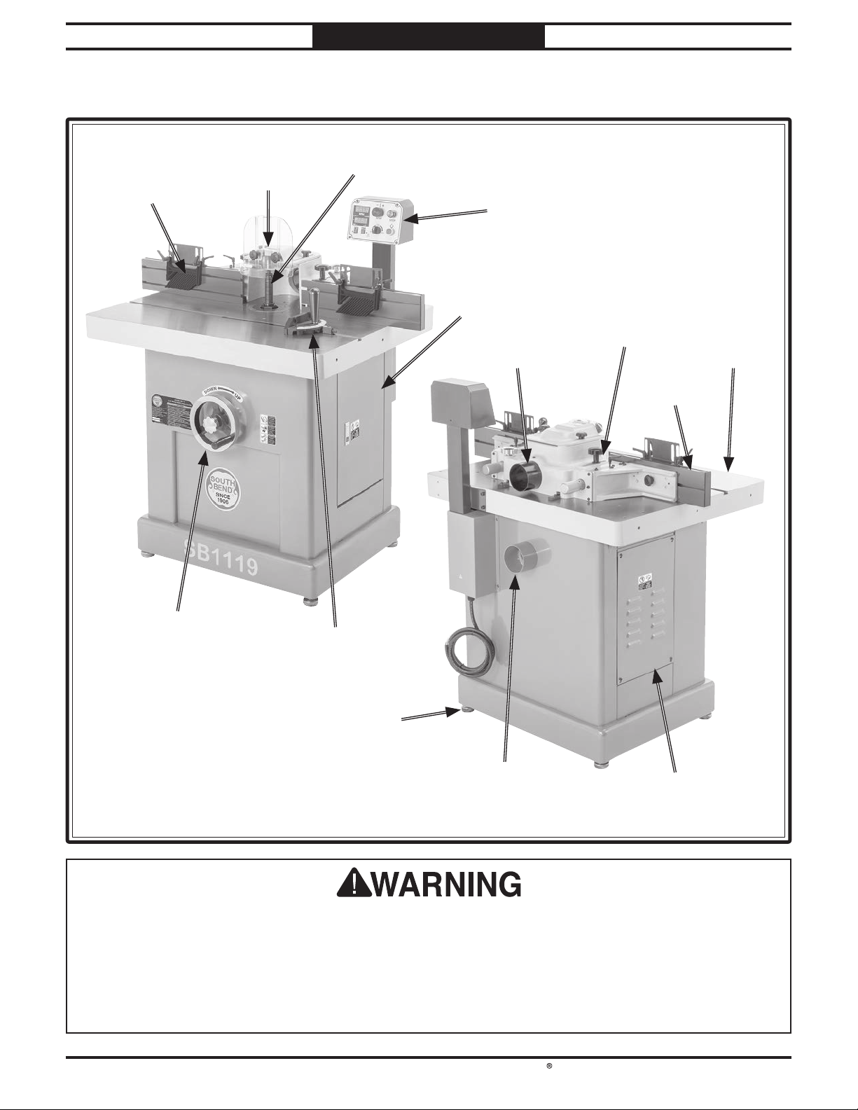
Identification
FenceFence
Work TableWork Table
For Your Own Safety Read Instruction Manual Before Operating Shaper
a) Wear eye protection.
b) Be sure keyed washer is directly under spindle nut and spindle nut is tight.
c) Feed workpiece against rotation of cutter.
d) Do not use awkward hand positions.
e) Keep fingers away from revolving cutter–use fixtures when necessary.
f) Use overhead guard when adjustable fence is not in place.
SpindleSpindle
ControlControl
PanelPanel
4" Dust Port4" Dust Port
SpindleSpindle
HeightHeight
HandwheelHandwheel
Cabinet AccessCabinet Access
PanelPanel
Cabinet DoorCabinet Door
Miter GaugeMiter Gauge
Machine FootMachine Foot
(1 of 4)(1 of 4)
Fence GuardFence Guard
AssemblyAssembly
CutterCutter
GuardGuard
Hold-DownHold-Down
FeatherboardFeatherboard
(1 of 2)(1 of 2)
4" Dust Port4" Dust Port

South Bend Tools
For Machines Mfd. Since 3/21 Model SB1119/SB1120
-3-
INTRODUCTION
Description of Controls
& Components
Refer to Figures 1–9 and the following
descriptions to become familiar with the basic
controls and components used to operate this
machine.
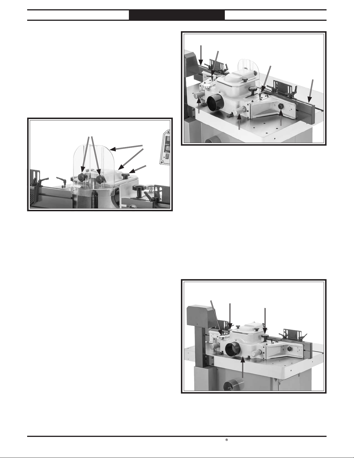
FigureFigure 1. Control panel.. Control panel.
AA
HH
GG
FF
BB
CC
DD
EE
JJ
FigureFigure 3. Cabinet components.. Cabinet components.
KK
J. Miter Gauge: Supports workpiece for
controlled straight or angled cuts as it slides
along the work table miter slot.
K. Spindle Height Handwheel: Raises and
lowers spindle and cutter to desired height.
Serious personal injury could occur if
you connect the machine to power before
completing the setup process. DO NOT
connect power until instructed to do so later
in this manual.
Untrained users have an increased risk
of seriously injuring themselves with this
machine. Do not operate this machine until
you have understood this entire manual and
received proper training.
A. RPM Digital Readout Screen: Displays
spindle RPM.
B. RPM Adjustment Knob: Adjusts spindle
speed between 5,000–10,000 RPM.
C. STOP Button: Turns machine OFF and
prevents it from starting.
D. ON Button: Turns machine ON.
E. Forward/Reverse (FOR/REV) Switch:
Starts, stops, and reverses spindle rotation.
F. Unit (mm/in.) Button: Switches spindle
height display to either inches or
millimeters.
G. Zeroing (0" Set) Button: Adjusts spindle/
cutter height to 0 in./mm.
H. Spindle Height Digital Readout Screen:
Displays spindle/cutter height in either
inches or millimeters.
II
FigureFigure 2. Starting pin.. Starting pin.
I. Starting Pin: Supports workpiece during
freehand cuts until it contacts rub collar
(refer to Page 36).
-4-
For Machines Mfd. Since 3/21
South Bend Tools
Model SB1119/SB1120 INTRODUCTION
O. Fence: Adjusts side to side and forward
and backward to support workpiece during
operation. Each fence is independently
adjustable and both can be removed and
replaced with a zero-clearance or other
custom-made fence.
P. Fence Lock Handles: Loosen to allow for
independent fence micro-adjustment and
tighten to secure.
Q. Fence Lock Knob (1 of 2): Loosens to allow
for independent fence adjustment in relation
to cutterhead (side to side) and tightens to
secure.
R. Fence Micro-Adjustment Knobs: Move each
fence independently forward and backward
(i.e., cutting depth). One turn moves each
fence approximately 1⁄64" (.015").
S. Guard/Fence Base Adjustment Knob:
Adjusts guard/fence base forward and
backward on table using rack and pinion.
One turn is approximately 15⁄8" of movement.
T. Guard/Fence Base Lock Knobs: Loosen to
allow for guard/fence base adjustment and
tighten to secure.
U. Guard/Fence Base: Adjusts forward and
backward on table to provide safety and
support as required by operation. Assembly
can be removed or adjusted to use custom-
made box guard for small stock or irregular
shaping.
OOPP
RRQQ
FigureFigure 5. Fence controls and components.. Fence controls and components.
PP
RR
OO
UU
SSTT
TT
FigureFigure 6. Guard/fence base controls and components.. Guard/fence base controls and components.
FigureFigure 4. Cutter guard controls and components.. Cutter guard controls and components.
MM
LL
NN
L. Guard Height Lock Knobs: Loosen to adjust
front cutter guard height and tighten to
secure.
M. Cutter Guard: Adjusts to protect user from
accidental cutter contact or chips thrown by
cutterhead.
N. Guard Position Lock Knob (1 of 2): Loosen to
adjust cutter guard forward or backward and
tighten to secure.
South Bend Tools
For Machines Mfd. Since 3/21 Model SB1119/SB1120
-5-
INTRODUCTION
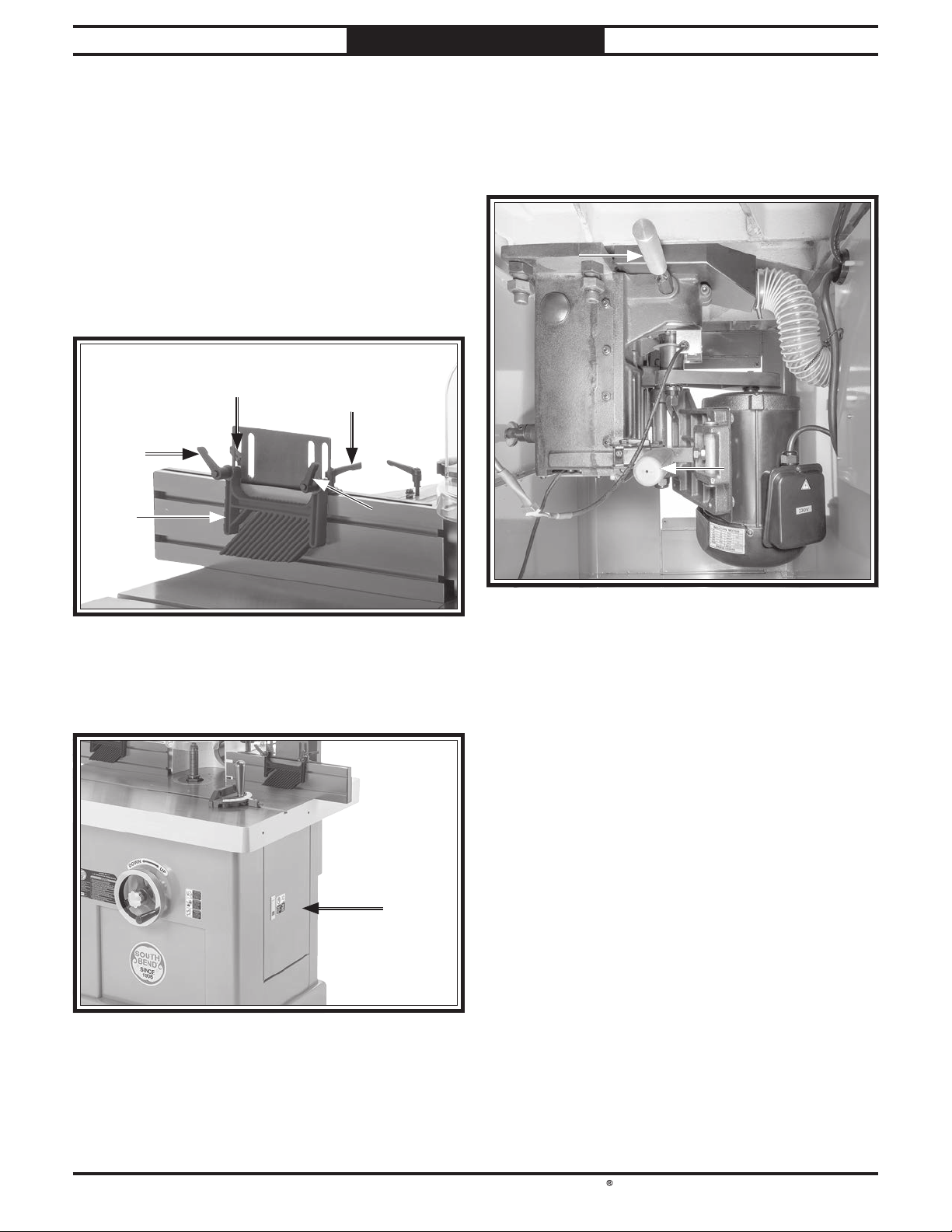
V. Featherboard Position Lock Handle: Loosen
to adjust featherboard closer or farther away
from cutterhead along fence (i.e., workpiece
length) and tighten to secure.
W. Featherboard Height Lock Handle: Loosen to
adjust featherboard closer or farther away
from table (i.e., workpiece thickness) and
tighten to secure.
X. Featherboard: Guides and supports
workpiece as it moves past cutterhead.
VV
XXWW
FigureFigure 7. Featherboard controls and components.. Featherboard controls and components.
VV
Z. Spindle Assembly Lock Handle: Locks/
unlocks spindle seat to change spindles.
AA. Motor Bracket Handle: Engages and releases
V-belt tension.
ZZ
FigureFigure 9. Inside cabinet controls.. Inside cabinet controls.
AAAA
WW
Y. Cabinet Door: Allows access to inside cabinet
for maintenance, service, or to change
spindles.
YY
FigureFigure 8. Cabinet door location.. Cabinet door location.

-6-
For Machines Mfd. Since 3/21
South Bend Tools
Model SB1119/SB1120 INTRODUCTION
SB1119 Product
Specifications
Model SB1119 Page 1 of 3
Model SB1119
3 HP SinglePhase Spindle Shaper
Product Dimensions
Weight............................................................................................................................................................. 660 lbs.
Width (side-to-side) x Depth (front-to-back) x Height......................................................... 39-1/2 x 34 x 51-1/2 in.
Footprint (Length x Width)................................................................................................................. 25-1/2 x 31 in.
Shipping Dimensions
Type.......................................................................................................................................................... Wood Crate
Content.......................................................................................................................................................... Machine
Weight............................................................................................................................................................. 780 lbs.
Length x Width x Height................................................................................................................... 44 x 39 x 58 in.
Electrical
Power Requirement......................................................................................................... 230V, Single-Phase, 60 Hz
Full-Load Current Rating.................................................................................................................................... 20A
Minimum Circuit Size.......................................................................................................................................... 20A
Connection Type..................................................................................................................................... Cord & Plug
Power Cord Included............................................................................................................................................. Yes
Power Cord Length.......................................................................................................................................... 120 in.
Power Cord Gauge......................................................................................................................................... 12 AWG
Plug Included........................................................................................................................................................ Yes
Included Plug Type.............................................................................................................................................. 6-20
Switch Type....................................................................................... Control Panel w/Magnetic Switch Protection
Inverter (VFD) Type............................................................................................................................. Delta ME300
Inverter (VFD) Size............................................................................................................................................ 3 HP
Motors
Main
Horsepower............................................................................................................................................... 3 HP
Phase.................................................................................................................................................... 3-Phase
Amps............................................................................................................................................................. 8A
Speed................................................................................................................................................ 3450 RPM
Type........................................................................................................................................ TEFC Induction
Power Transfer .......................................................................................................................................... Belt
Bearings................................................................................................ Shielded & Permanently Lubricated
Product Specifications
P.O. Box 2027, Bellingham, WA 98227 U.S.A.
www.southbendtools.com
PHONE: (360) 734-1540 • © South Bend Tools

South Bend Tools
For Machines Mfd. Since 3/21 Model SB1119/SB1120
-7-
INTRODUCTION
Model SB1119 Page 2 of 3
Main Specifications
Operation Info
Max. Cutter Height.................................................................................................................................... 5 in.
Max. Cutter Diameter............................................................................................................................... 7 in.
Spindle Sizes................................................................................................................................. 3/4, 1-1/4 in.
Spindle Lengths......................................................................................................................... 3-7/8, 5-7/8 in.
Exposed Spindle Length........................................................................................................... 3-7/8, 5-7/8 in.
Spindle Cap. Under the Nut..................................................................................................... 3-1/2, 5-1/8 in.
Spindle Speeds................................................................................................................... 5000 - 10,000 RPM
Spindle Travel............................................................................................................................................ 4 in.
Spindle Openings........................................................................................................ 2-1/2, 4-1/8, 5-3/4, 7 in.
Table Info
Number of Table Inserts................................................................................................................................. 3
Table Insert Sizes I.D..................................................................................................... 2-1/2, 4-1/8, 5-3/4 in.
Table Insert Sizes O.D.................................................................................................... 4-5/8, 6-1/4, 8-3/8 in.
Table Counterbore Diameter.............................................................................................................. 8-1/4 in.
Table Counterbore Depth..................................................................................................................... 3/16 in.
Table Size Length.............................................................................................................................. 39-1/4 in.
Table Size Width............................................................................................................................... 31-1/2 in.
Table Size Thickness........................................................................................................................... 3-1/4 in.
Floor to Table Height........................................................................................................................ 36-1/4 in.
Table Fence Length........................................................................................................................... 44-1/2 in.
Table Fence Width............................................................................................................................... 1-1/4 in.
Table Fence Height.............................................................................................................................. 4-3/4 in.
Miter Gauge Info
Miter Angle................................................................................................................................ 0 - 60 deg. L/R
Miter Gauge Slot Type............................................................................................................................ T-Slot
Miter Gauge Slot Width......................................................................................................................... 3/4 in.
Miter Gauge Slot Height........................................................................................................................ 3/8 in.
Construction
Table.................................................................................................................... Precision-Ground Cast Iron
Cabinet........................................................................................................................................ Formed Steel
Fence................................................................................................................................................ Aluminum
Miter Gauge..................................................................................................................................... Aluminum
Guard......................................................................................................................................... Polycarbonate
Spindle Bearings............................................................................................................. Sealed & Lubricated
Paint Type/Finish................................................................................................................................. Enamel
Other
Number of Dust Ports..................................................................................................................................... 2
Dust Port Size............................................................................................................................................ 4 in.
Other
Country of Origin ........................................................................................................................................... Taiwan
Warranty ........................................................................................................................................................ 2 Years
Approximate Assembly & Setup Time ................................................................................................... 30 Minutes
Serial Number Location .............................................................................................................................. ID Label
Sound Rating .................................................................................................................................................... 85 dB
ISO 9001 Factory ................................................................................................................................................. Yes
Certified by a Nationally Recognized Testing Laboratory (NRTL) ................................................................... Yes

-8-
For Machines Mfd. Since 3/21
South Bend Tools
Model SB1119/SB1120 INTRODUCTION
Model SB1120 Page 1 of 3
Model SB1120
5 HP 3Phase Spindle Shaper
Product Dimensions
Weight............................................................................................................................................................. 682 lbs.
Width (side-to-side) x Depth (front-to-back) x Height......................................................... 39-1/2 x 34 x 51-1/2 in.
Footprint (Length x Width)................................................................................................................. 25-1/2 x 31 in.
Shipping Dimensions
Type.......................................................................................................................................................... Wood Crate
Content.......................................................................................................................................................... Machine
Weight............................................................................................................................................................. 800 lbs.
Length x Width x Height................................................................................................................... 44 x 39 x 58 in.
Electrical
Power Requirement................................................................................................................. 230V, 3-Phase, 60 Hz
Full-Load Current Rating................................................................................................................................. 16.5A
Minimum Circuit Size.......................................................................................................................................... 20A
Connection Type..................................................................................................................................... Cord & Plug
Power Cord Included............................................................................................................................................. Yes
Power Cord Length.......................................................................................................................................... 120 in.
Power Cord Gauge......................................................................................................................................... 12 AWG
Plug Included........................................................................................................................................................ Yes
Included Plug Type.......................................................................................................................................... L15-20
Switch Type....................................................................................... Control Panel w/Magnetic Switch Protection
Inverter (VFD) Type............................................................................................................................. Delta ME300
Inverter (VFD) Size............................................................................................................................................ 5 HP
Motors
Main
Horsepower............................................................................................................................................... 5 HP
Phase.................................................................................................................................................... 3-Phase
Amps........................................................................................................................................................... 16.5
Speed................................................................................................................................................ 3450 RPM
Type........................................................................................................................................ TEFC Induction
Power Transfer .......................................................................................................................................... Belt
Bearings................................................................................................ Shielded & Permanently Lubricated
Product Specifications
P.O. Box 2027, Bellingham, WA 98227 U.S.A.
www.southbendtools.com
PHONE: (360) 734-1540 • © South Bend Tools

South Bend Tools
For Machines Mfd. Since 3/21 Model SB1119/SB1120
-9-
INTRODUCTION
Model SB1120 Page 2 of 3
Main Specifications
Operation Info
Max. Cutter Height.................................................................................................................................... 5 in.
Max. Cutter Diameter............................................................................................................................... 7 in.
Spindle Sizes................................................................................................................................. 3/4, 1-1/4 in.
Spindle Lengths......................................................................................................................... 3-7/8, 5-7/8 in.
Exposed Spindle Length........................................................................................................... 3-7/8, 5-7/8 in.
Spindle Cap. Under the Nut..................................................................................................... 3-1/2, 5-1/8 in.
Spindle Speeds................................................................................................................... 5000 - 10,000 RPM
Spindle Travel............................................................................................................................................ 4 in.
Spindle Openings........................................................................................................ 2-1/2, 4-1/8, 5-3/4, 7 in.
Table Info
Number of Table Inserts................................................................................................................................. 3
Table Insert Sizes I.D..................................................................................................... 2-1/2, 4-1/8, 5-3/4 in.
Table Insert Sizes O.D.................................................................................................... 4-5/8, 6-1/4, 8-3/8 in.
Table Counterbore Diameter.............................................................................................................. 8-1/4 in.
Table Counterbore Depth..................................................................................................................... 3/16 in.
Table Size Length.............................................................................................................................. 39-1/4 in.
Table Size Width............................................................................................................................... 31-1/2 in.
Table Size Thickness........................................................................................................................... 3-1/4 in.
Floor to Table Height........................................................................................................................ 36-1/4 in.
Table Fence Length........................................................................................................................... 44-1/2 in.
Table Fence Width............................................................................................................................... 1-1/4 in.
Table Fence Height.............................................................................................................................. 4-3/4 in.
Miter Gauge Info
Miter Angle................................................................................................................................ 0 - 60 deg. L/R
Miter Gauge Slot Type............................................................................................................................ T-Slot
Miter Gauge Slot Width......................................................................................................................... 3/4 in.
Miter Gauge Slot Height........................................................................................................................ 3/8 in.
Construction
Table.................................................................................................................... Precision-Ground Cast Iron
Cabinet........................................................................................................................................ Formed Steel
Fence................................................................................................................................................ Aluminum
Miter Gauge..................................................................................................................................... Aluminum
Guard......................................................................................................................................... Polycarbonate
Spindle Bearings............................................................................................................. Sealed & Lubricated
Paint Type/Finish................................................................................................................................. Enamel
Other
Number of Dust Ports..................................................................................................................................... 2
Dust Port Size............................................................................................................................................ 4 in.
Other
Country of Origin ........................................................................................................................................... Taiwan
Warranty ........................................................................................................................................................ 2 Years
Approximate Assembly & Setup Time ................................................................................................... 30 Minutes
Serial Number Location .............................................................................................................................. ID Label
Sound Rating .................................................................................................................................................... 85 dB
ISO 9001 Factory ................................................................................................................................................. Yes
Certified by a Nationally Recognized Testing Laboratory (NRTL) ................................................................... Yes

SAFETY
-10-
For Machines Mfd. Since 3/21
South Bend Tools
Model SB1119/SB1120 SAFETY
Understanding Risks of Machinery
Operating all machinery and machining equipment can be dangerous or relatively safe depending
on how it is installed and maintained, and the operator's experience, common sense, risk awareness,
working conditions, and use of personal protective equipment (safety glasses, respirators, etc.).
The owner of this machinery or equipment is ultimately responsible for its safe use. This
responsibility includes proper installation in a safe environment, personnel training and usage
authorization, regular inspection and maintenance, manual availability and comprehension,
application of safety devices, integrity of cutting tools or accessories, and the usage of approved
personal protective equipment by all operators and bystanders.
The manufacturer of this machinery or equipment will not be held liable for injury or property
damage from negligence, improper training, machine modifications, or misuse. Failure to read,
understand, and follow the manual and safety labels may result in serious personal injury, including
amputation, broken bones, electrocution, or death.
The signals used in this manual to identify hazard levels are as follows:
Death or catastrophic
harm WILL occur.
Moderate injury or fire
MAY occur.
Death or catastrophic
harm COULD occur.
Machine or property
damage may occur.
Basic Machine Safety
Owner’s Manual: All machinery and machining
equipment presents serious injury hazards
to untrained users. To reduce the risk of
injury, anyone who uses THIS item MUST
read and understand this entire manual
before starting.
Personal Protective Equipment: Operating or
servicing this item may expose the user
to flying debris, dust, smoke, dangerous
chemicals, or loud noises. These hazards
can result in eye injury, blindness, long-
term respiratory damage, poisoning,
cancer, reproductive harm or hearing loss.
Reduce your risks from these hazards
by wearing approved eye protection,
respirator, gloves, or hearing protection.
Trained/Supervised Operators Only: Untrained
users can seriously injure themselves
or bystanders. Only allow trained and
properly supervised personnel to operate
this item. Make sure safe operation
instructions are clearly understood. If
electrically powered, use padlocks and
master switches, and remove start switch
keys to prevent unauthorized use or
accidental starting.
Guards/Covers: Accidental contact with
moving parts during operation may cause
severe entanglement, impact, cutting,
or crushing injuries. Reduce this risk by
keeping any included guards/covers/doors
installed, fully functional, and positioned
for maximum protection.

South Bend Tools
For Machines Mfd. Since 3/21 Model SB1119/SB1120
-11-
SAFETY
Entanglement: Loose clothing, gloves, neckties,
jewelry or long hair may get caught in
moving parts, causing entanglement,
amputation, crushing, or strangulation.
Reduce this risk by removing/securing
these items so they cannot contact moving
parts.
Mental Alertness: Operating this item with
reduced mental alertness increases the
risk of accidental injury. Do not let a
temporary influence or distraction lead to a
permanent disability! Never operate when
under the influence of drugs/alcohol, when
tired, or otherwise distracted.
Safe Environment: Operating electrically
powered equipment in a wet environment
may result in electrocution; operating near
highly flammable materials may result in a
fire or explosion. Only operate this item in
a dry location that is free from flammable
materials.
Electrical Connection: With electically powered
equipment, improper connections to the
power source may result in electrocution
or fire. Always adhere to all electrical
requirements and applicable codes when
connecting to the power source. Have all
work inspected by a qualified electrician to
minimize risk.
Disconnect Power: Adjusting or servicing
electrically powered equipment while it
is connected to the power source greatly
increases the risk of injury from accidental
startup. Always disconnect power
BEFORE any service or adjustments,
including changing blades or other tooling.
Secure Workpiece/Tooling: Loose workpieces,
cutting tools, or rotating spindles can
become dangerous projectiles if not
secured or if they hit another object during
operation. Reduce the risk of this hazard
by verifying that all fastening devices are
properly secured and items attached to
spindles have enough clearance to safely
rotate.
Chuck Keys or Adjusting Tools: Tools used to
adjust spindles, chucks, or any moving/
rotating parts will become dangerous
projectiles if left in place when the machine
is started. Reduce this risk by developing
the habit of always removing these tools
immediately after using them.
Work Area: Clutter and dark shadows increase
the risks of accidental injury. Only operate
this item in a clean, non-glaring, and well-
lighted work area.
Properly Functioning Equipment: Poorly
maintained, damaged, or malfunctioning
equipment has higher risks of causing
serious personal injury compared to
those that are properly maintained.
To reduce this risk, always maintain
this item to the highest standards and
promptly repair/service a damaged or
malfunctioning component. Always follow
the maintenance instructions included in
this documentation.
Unattended Operation: Electrically powered
equipment that is left unattended while
running cannot be controlled and is
dangerous to bystanders. Always turn the
power OFF before walking away.
Health Hazards: Certain cutting fluids and
lubricants, or dust/smoke created when
cutting, may contain chemicals known to
the State of California to cause cancer,
respiratory problems, birth defects,
or other reproductive harm. Minimize
exposure to these chemicals by wearing
approved personal protective equipment
and operating in a well ventilated area.
Difficult Operations: Attempting difficult
operations with which you are unfamiliar
increases the risk of injury. If you
experience difficulties performing the
intended operation, STOP! Seek an
alternative method to accomplish the
same task, ask a qualified expert how the
operation should be performed, or contact
our Technical Support for assistance.

-12-
For Machines Mfd. Since 3/21
South Bend Tools
Model SB1119/SB1120 SAFETY
Additional Shaper Safety
Small Workpieces: There is a high risk of
accidental cutter contact with small
workpieces, because they are closer to cutter
and more difficult to control. To reduce
risk, only feed small workpieces using jigs
or holding fixtures that allow hands to stay
safely away from cutter. When possible,
shape longer stock and cut to size.
Safe Cutter Clearances: Operator or bystanders
may be hit by flying debris if cutter contacts
fence, guard, or table insert upon startup.
Always ensure any cutter setup has proper
cutter rotational clearance before startup.
Safe Cutter Installation: Improperly secured
knives/inserts, cutters, or rub collars may
become dangerous projectiles if they come
loose. Always ensure keyed washer is
directly under cap screw and cap screw is
very secure. If spindle does not use a keyed
washer, always tighten two spindle nuts
together, and ensure BOTH are very secure.
Never use cutters/bits rated for an RPM
lower than spindle speed.
Avoiding Climb Cuts: Feeding workpiece in
same direction of cutter rotation is a “climb
cut.” Climb cutting can aggressively pull
workpiece—and hands—into cutter. Always
first verify direction of cutter rotation
before starting, and always feed workpiece
AGAINST cutter rotation.
Cutting Depth: Never attempt to remove too
much material in one pass. Doing this
increases risk of kickback. Instead, make
several light passes—this is a safer way to
cut and it leaves a cleaner finish.
Contour Shaping: To reduce risk of unintentional
cutter contact while freehand shaping
or using rub collar as guide, always use
overhead or “ring” type guard. To reduce
kickback risk, always use starting pin or
pivot board when starting cut. NEVER start
shaping at a corner!
Avoiding Cutter Contact: Keep unused portion of
cutter below table. Use smallest table insert
possible. Adjust fences and guards as close
as practical to cutter, or use zero-clearance
fence or box guard. Always keep some type
of guard or other protective device between
your hands and cutter at all times!
Protect Hands/Fingers: While feeding workpiece,
avoid awkward hand positions. Never pass
hands directly over, or in front of, cutter.
As one hand approaches 6-inch radius point
from cutter, move it in arc motion away from
cutter, and reposition it on outfeed side.
Feeding Workpiece: To reduce risk of accidental
cutterhead contact, always use push blocks
or some type of fixture, jig, or hold-down
device to safely feed workpiece while
cutting. Use outfeed support table if shaping
long workpieces to ensure proper support
throughout entire cutting procedure.
ALWAYS feed workpiece AGAINST
rotation of cutter. NEVER start shaper with
workpiece contacting cutter!
Safety Guards: To reduce risk of unintentional
contact with cutter, always ensure included
cutter guard, or properly dimensioned
box guard, or some other type of guard is
installed and correctly positioned before
operation.
Workpiece Condition: Shaping workpiece with
knots, holes, or foreign objects increases
risk of kickback and cutter damage/
breakage. Thoroughly inspect and prepare
workpiece before shaping. Always “square
up” workpiece before shaping or flatten
workpiece edges with jointer or planer.
Rough, warped, or wet workpieces increase
risk of kickback.
Cutter Positioning: Whenever possible, make
shaping cuts with cutter on underside of
workpiece to reduce operator exposure to
cutter.
Serious cuts, amputation, entanglement, or death can occur from contact with rotating cutter.
Cutters or other parts improperly secured to spindle can fly off and strike nearby operators with
great force. Flying debris can cause eye injuries or blindness. To minimize risk of getting hurt or
killed, anyone operating shaper MUST completely heed hazards and warnings below.

PREPARATION
South Bend Tools
For Machines Mfd. Since 3/21 Model SB1119/SB1120
-13-
PREPARATION
Like all machinery there is potential danger
when operating this machine. Accidents are
frequently caused by lack of familiarity or
failure to pay attention. Use this machine with
respect and caution to decrease the risk of
operator injury. If normal safety precautions
are overlooked or ignored, serious personal
injury may occur.
No list of safety guidelines can be complete.
Every shop environment is different. Always
consider safety first, as it applies to your
individual working conditions. Use this and
other machinery with caution and respect.
Failure to do so may result in serious personal
injury or property damage.
Preparation Overview Required for Setup
The purpose of the preparation section is to help
you prepare your machine for operation. The list
below outlines the basic process. Specific steps
for each of these points will be covered in detail
later in this section.
The typical preparation process is as follows:
1. Unpack the machine and inventory the
contents of the box/crate.
2. Clean the machine and its components.
3. Identify an acceptable location for the
machine and move it to that location.
4. Level the machine and either bolt it to the
floor or place it on mounts.
5. Assemble the loose components and make
any necessary adjustments or inspections to
ensure the machine is ready for operation.
6. Connect the machine to the power source.
7. Test run the machine to make sure it
functions properly and is ready for operation.
The items listed below are required to
successfully set up and prepare this machine for
operation.
For Lifting
• A forklift or other power lifting device rated
for the weight of the machine.
• Lifting Straps or Chain (rated for at least
1000 lbs.)
For Power Connection
• A power source that meets the minimum
circuit requirements for this machine. (Refer
to the Power Supply Requirements
section for details.)
• A qualified electrician to ensure a safe and
code-compliant connection to the power
source.
For Assembly
• Disposable Rags
• Cleaner/Degreaser
• Safety Glasses
• Disposable Gloves
• Straightedge 12"
• Socket or Wrench 13⁄16"
• Precision Level
• Dust Collection System
• Dust Hose 4"
• Hose Clamp 4"

-14-
For Machines Mfd. Since 3/21
South Bend Tools
Model SB1119/SB1120 PREPARATION
Power Supply
Requirements
Electrocution or fire may
occur if machine is not
correctly grounded and
attached to the power
supply. Use a qualified
electrician to ensure a safe
power connection.
Before installing the machine, consider the
availability and proximity of the required power
supply circuit. If an existing circuit does not meet
the requirements for this machine, a new circuit
must be installed.
To minimize the risk of electrocution, fire,
or equipment damage, installation work and
electrical wiring must be done by a
n electrician
or qualified service personnel
in accordance with
applicable electrical codes and safety standards.
Availability
The full-load current rating is the amperage
a machine draws at 100% of the rated output
power. On machines with multiple motors, this is
the amperage drawn by the largest motor or sum
of all motors and electrical devices that might
operate at one time during normal operations.
The full-load current is not the maximum
amount of amps that the machine will draw. If
the machine is overloaded, it will draw additional
amps beyond the full-load rating.
If the machine is overloaded for a sufficient
length of time, damage, overheating, or fire may
result—especially if connected to an undersized
circuit. To reduce the risk of these hazards,
avoid overloading the machine during operation
and make sure it is connected to a power supply
circuit that meets the requirements in the
following section.
Full-Load Current Rating
Full-Load Rating (SB1119) ................ 20 Amps
Grounding Requirements
This machine must be grounded! In the event
of
certain types of malfunctions or breakdowns,
grounding provides a path of least resistance
for electric current
in order to reduce the risk of
electric shock.
Improper connection of the equipment-grounding
wire can result in a risk of electric shock. The
wire with green insulation (with or without
yellow stripes) is the equipment-grounding wire.
If repair or replacement of the power cord or
plug is necessary, do not connect the equipment-
grounding wire to a live (current carrying)
terminal.
Check with an electrician or qualified service
personnel if you do not understand these
grounding requirements, or if you are in doubt
about whether the tool is properly grounded.
If you ever notice that a cord or plug is
damaged or worn, disconnect it from power, and
immediately replace it with a new one.
Full-Load Rating (SB1120) ............. 16.5 Amps
For your own safety and protection of property,
consult an electrician if you are unsure about
wiring practices or applicable electrical codes.
Note: The circuit requirements in this manual
are for
a dedicated circuit—where only one
machine will be running at a time. If this
machine will be connected to a shared circuit
where multiple machines will be running at
the same time, consult a qualified electrician to
ensure the circuit is properly sized.
A power supply circuit includes all electrical
equipment between the main breaker box or fuse
panel in your building and the incoming power
connections inside the machine. This circuit
must be safely sized to handle the full-load
current that may be drawn from the machine for
an extended period of time. (If this machine is
connected to a circuit protected by fuses, use a
time delay fuse marked D.)
Circuit Information
South Bend Tools
For Machines Mfd. Since 3/21 Model SB1119/SB1120
-15-
PREPARATION
SB1119 Circuit Requirements
This machine is prewired to operate on a power
supply circuit that has a verified ground and
meets the following requirements:
Nominal Voltage ........... 208V/220V/230V/240V
Cycle .............................................................60 Hz
Phase ..............................................Single-Phase
Circuit Rating....................................... 20 Amps
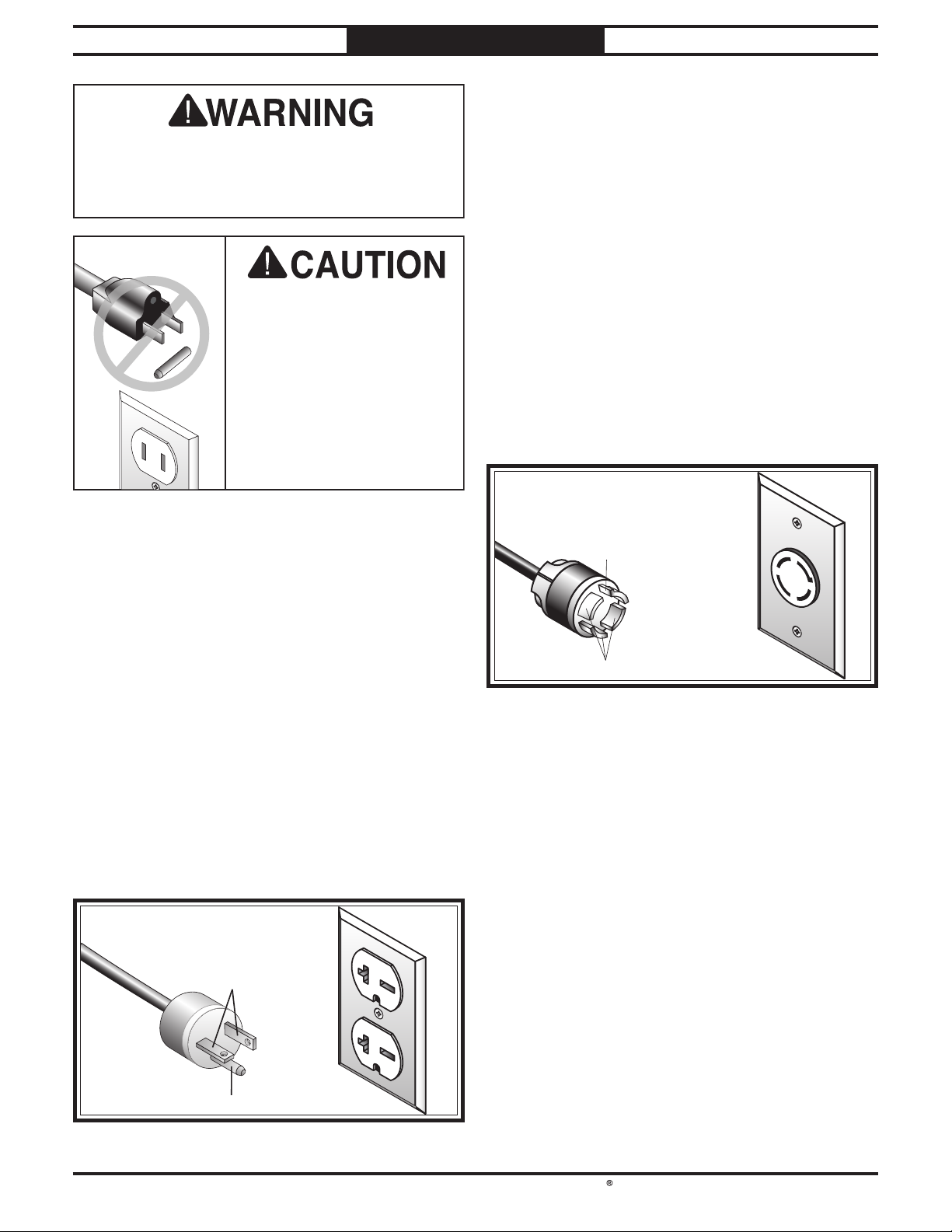
Plug/Receptacle (included) ...........NEMA 6-20
Serious injury could occur if you connect
the machine to power before completing the
setup process. DO NOT connect to power until
instructed later in this manual.
This machine is equipped with a power cord
that has
an equipment-grounding wire and a
grounding plug
(similar to the figure below).
The plug
must only be inserted into a matching
receptacle (outlet)
that is properly installed and
grounded in accordance with all local codes and
ordinances.
Grounding Prong
Current Carrying Prongs
6-20 PLUG
GROUNDED
6-20 RECEPTACLE
FigureFigure 10. NEMA 6-20 plug and receptacle.. NEMA 6-20 plug and receptacle.
DO NOT modify the
included plug or use an
adapter if it will not fit your
receptacle. Instead, have a
qualified electrician install
the proper receptacle on a
power supply circuit that
is grounded and meets
the requirements for this
machine.
Extension Cords
Minimum Gauge Size............................10 AWG
Maximum Length (Shorter is Better) ....50 ft.
We do not recommend using an extension cord
with this machine. If you must use one, only
use it if absolutely necessary and only on a
temporary basis.
Extension cords cause voltage drop, which may
damage electrical components and shorten motor
life. Voltage drop increases as the extension cord
size gets longer and the gauge size gets smaller
(higher gauge numbers indicate smaller sizes).
Any extension cord used with this machine
must contain a ground wire, match the required
plug and receptacle listed in the
Circuit
Requirements
for the applicable voltage, and
meet the following requirements:
SB1120 Circuit Requirements
This machine is prewired to operate on a power
supply circuit that has a verified ground and
meets the following requirements:
Nominal Voltage ........... 208V/220V/230V/240V
Cycle .............................................................60 Hz
Phase ....................................................... 3-Phase
Circuit Rating....................................... 20 Amps
Plug/Receptacle (included) ......NEMA L15-20
This machine is equipped with a power cord
that has
an equipment-grounding wire and a
grounding plug
(similar to the figure below).
The plug
must only be inserted into a matching
receptacle (outlet)
that is properly installed and
grounded in accordance with all local codes and
ordinances.
Grounding Prong
is Hooked
Current Carrying Prongs
GROUNDED
L15-20 RECEPTACLE
L15-20
PLUG
FigureFigure 11. NEMA L15-20 plug and receptacle.. NEMA L15-20 plug and receptacle.

-16 -
For Machines Mfd. Since 3/21
South Bend Tools
Model SB1119/SB1120 PREPARATION
Unpacking
This item was carefully packaged to prevent
damage during transport. If you discover any
damage, please immediately call Customer
Service at
(360) 734-1540 for advice. You may
need to file a freight claim, so save the containers
and all packing materials for possible inspection
by the carrier or its agent.
Inventory
NOTICE
If you cannot find an item on this list, carefully
check around/inside the machine and
packaging materials. Often, these items get
lost in packaging materials while unpacking or
they are pre-installed at the factory.
Inventory (Figure 12) Qty
A. Shaper (Not Shown)....................................... 1
B. Spindle 11⁄4" w/Spacers................................... 1
C. Spindle 3⁄4" w/Spacers..................................... 1
D. Drawbar.......................................................... 1
E. Starting Pin....................................................1
F. Combo Screwdriver #1, 1⁄4".............................1
G. Hex Wrenches 3, 6mm ............................ 1 Ea.
H. Spindle Wrench 50mm ..................................1
I. Open-End Wrench 22 x 24mm ......................1
J. Open-End Wrench 14 x 17mm ......................1
K. Miter Gauge ...................................................1
FigureFigure 12. Inventory.. Inventory.
CCBBDD
FF
EE
GG
II
HH
JJ
KK

South Bend Tools
For Machines Mfd. Since 3/21 Model SB1119/SB1120
-17-
PREPARATION
The unpainted surfaces are coated
at the factory
with a heavy-duty rust preventative that
prevents corrosion during shipment and
storage.
The benefit of this rust preventative is that it
works very well. The downside is that it
can be
time-consuming
to thoroughly remove.
Be patient and do a careful job when
cleaning
and removing the rust preventative
. The time
you spend doing this will reward you with
smooth
-sliding parts and a better appreciation
for the proper care of
the unpainted surfaces.
Although there are many ways to successfully
remove the rust preventative, the
following
process works well in most situations
.
Before cleaning, gather the following:
• Disposable
rags
• Cleaner/degreaser
(certain citrus-based
degreasers work extremely well and they
have non-toxic fumes)
• Safety glasses & disposable gloves
Note:
Automotive degreasers, mineral spirits, or
WD•40 can be used to remove rust preventative.
Before using these products, though, test them
on an inconspicuous area of a painted surface to
make sure they will not damage it.
Basic steps for removing rust preventative:
1. Put on safety glasses and disposable gloves.
2. Coat all surfaces that have rust preventative
with a liberal amount of your cleaner or
degreaser and let them soak for a few
minutes.
3. Wipe off the surfaces. If your cleaner or
degreaser is effective, the rust preventative
will wipe off easily.
Note: To clean off thick coats of rust
preventative on flat surfaces, such as beds
or tables, use a PLASTIC paint scraper to
scrape off the majority of the coating before
wiping it off with your rag. (Do not use a
metal scraper or it may scratch the surface.)
4. Repeat Steps 2–3 as necessary until clean,
then coat all unpainted surfaces with a
quality metal protectant or light oil to
prevent rust.
GAS
Gasoline and petroleum
products have low flash
points and can explode
or cause fire if used for
cleaning. Avoid using these
products to remove rust
preventative.
Many cleaning solvents are
toxic if inhaled. Minimize
your risk by only using
these products in a well
ventilated area.
Avoid chlorine-based solvents, such as
acetone or brake parts cleaner that may
damage painted surfaces. Always follow the
manufacturer’s instructions when using any
type of cleaning product.
T23692—Orange Power Degreaser
A great product for removing the waxy shipping
grease from the non-painted parts of the
machine during clean up.
Cleaning & Protecting
FigureFigure 13.. T23692 Orange Power Degreaser.
-18-
For Machines Mfd. Since 3/21
South Bend Tools
Model SB1119/SB1120 PREPARATION
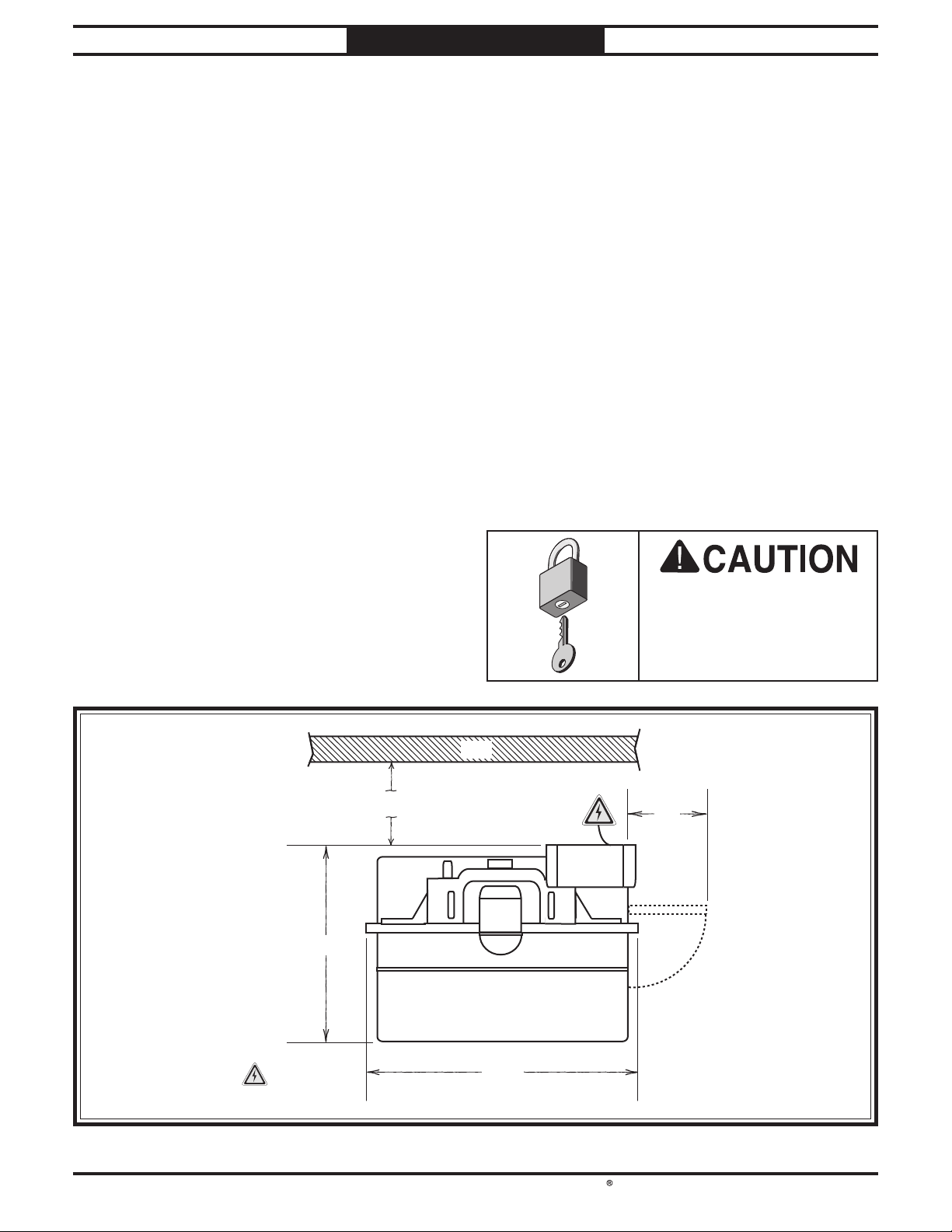
Min. 30"
Electrical
Connection
=
Wall
39½"
34"
13"
Figure 14. Minimum working clearances.Figure 14. Minimum working clearances.
Physical Environment
Electrical Installation
Lighting
Weight Load
Space Allocation
Weight Load
Refer to the Machine Specifications for the
weight of your machine. Make sure that the
surface upon which the machine is placed will
bear the weight of the machine, additional
equipment that may be installed on the machine,
and the heaviest workpiece that will be used.
Additionally, consider the weight of the operator
and any dynamic loading that may occur when
operating the machine.
Space Allocation
Consider the largest size of workpiece that will
be processed through this machine and provide
enough space around the machine for adequate
operator material handling or the installation
of auxiliary equipment. With permanent
installations, leave enough space around
the machine to open or remove doors/covers
as required by the maintenance and service
described in this manual.
Physical Environment
The physical environment where your machine
is operated is important for safe operation and
longevity of
parts. For best results, operate this
machine in a dry environment that is free from
excessive moisture, hazardous
or flammable
chemicals, airborne abrasives, or extreme
conditions. Extreme conditions for this type
of machinery are generally those where the
ambient temperature
is outside the range of 41°–
104°F; the relative humidity
is outside the range
of
20–95% (non-condensing); or the environment
is subject to vibration, shocks, or bumps.
Electrical Installation
Place this machine near an existing power
source. Make sure all power cords are protected
from traffic, material handling, moisture,
chemicals, or other hazards. Make sure to leave
access to a means of disconnecting the power
source or engaging a lockout/tagout device.
Lighting
Lighting around the machine must be adequate
enough to perform operations safely. Shadows,
glare, or strobe effects that may distract or
impede the operator must be eliminated.
Children or untrained
people may be seriously
injured by this machine.
Only install in an access
restricted location.
Location
This manual suits for next models
1
Table of contents
Other South Bend Tools Power Tools manuals


