South Bend Tools SB1125 User manual

®
A Tradition of Excellence
South Bend Tools
© December, 2021 by South Bend Tools For Machines Mfd. Since 11/21 (V1.12.21)
MODEL SB1125
19½" FLOOR DRILL PRESS
OWNER'S MANUAL

Customer Service
We stand behind our machines. If you have any service questions, parts requests or general questions
about your purchase, feel free to contact us.
South Bend Tools
P.O. Box 2027
Bellingham, WA 98227
Phone: (360) 734-1540
Fax: (360) 676-1075 (International)
Fax: (360) 734-1639 (USA Only)
Email: [email protected]
Updates
For your convenience, any updates to this manual will be available to download free of charge
through our website at:
www.southbendtools.com
Scope of Manual
This manual helps the reader understand the machine, how to prepare it for operation, how to control
it during operation, and how to keep it in good working condition. We assume the reader has a basic
understanding of how to operate this type of machine, but that the reader is not familiar with the
controls and adjustments of this specific model. As with all machinery of this nature, learning the
nuances of operation is a process that happens through training and experience. If you are not an
experienced operator of this type of machinery, read through this entire manual, then learn more
from an experienced operator, schooling, or research before attempting operations. Following this
advice will help you avoid serious personal injury and get the best results from your work.
Manual Feedback
We've made every effort to be accurate when documenting this machine. However, errors sometimes
happen or the machine design changes after the documentation process—so
the manual may not
exactly match your machine.
If a difference between the manual and machine leaves you in doubt,
contact our
customer service for clarification.
We highly value customer feedback on our manuals. If you have a moment, please share your
experience using this manual. What did you like about it? Is there anything you would change to
make it better? Did it meet your expectations for clarity, professionalism, and ease-of-use?
South Bend Tools
C
/O Technical Documentation Manager

Table of Contents
ACCESSORIES.............................................................. 29
MAINTENANCE ............................................................. 32
Maintenance Schedule....................................... 32
Cleaning & Protecting .......................................32
Lubrication......................................................... 32
Machine Storage ................................................35
Checking V-Belts ...............................................35
SERVICE...........................................................................36
Adjusting Return Spring Tension.....................36
Replacing V-Belts...............................................37
Aligning Motor Pulley........................................39
Replacing Worklight Bulb .................................40
TROUBLESHOOTING................................................. 41
ELECTRICAL...................................................................44
Electrical Safety Instructions ...........................44
Wiring Diagram .................................................45
Electrical Component Pictures..........................46
PARTS................................................................................ 47
Headstock........................................................... 47
Control Box.........................................................49
Column ...............................................................50
Machine Labels ..................................................52
WARRANTY..................................................................... 53
INTRODUCTION...............................................................2
Identification ........................................................2
Description of Controls & Components ..............3
Product Specifications ......................................... 5
SAFETY................................................................................7
Understanding Risks of Machinery ....................7
Basic Machine Safety ..........................................7
Additional Drill Press Safety ..............................9
PREPARATION .............................................................. 10
Preparation Overview........................................ 10
Required for Setup............................................. 10
Power Supply Requirements.............................11
Unpacking ..........................................................13
Inventory ............................................................13
Cleaning & Protecting .......................................14
Location ..............................................................15
Placing & Anchoring Machine ..........................16
Joining Drill Chuck & Arbor.............................18
Assembly ............................................................18
Test Run .............................................................19
Spindle Break-In................................................ 21
OPERATION.................................................................... 22
Operation Overview........................................... 22
Installing/Removing Arbor................................23
Installing/Removing Drill Bit............................ 24
Spindle Speed..................................................... 25
Calculating Spindle Speed for Drilling.............27
Adjusting Depth Stop ........................................28
Positioning Table ...............................................28

INTRODUCTION
-2-
For Machines Mfd. Since 11/21
South Bend Tools
Model SB1125 INTRODUCTION
Identification
MotorMotor
Spindle ReturnSpindle Return
SpringSpring
TableTable
ChuckChuck
DownfeedDownfeed
HandleHandle
(1 of 3)(1 of 3)
ColumnColumn
Table RotationTable Rotation
Lock HandleLock Handle
Table HeightTable Height
Lock HandleLock Handle
BaseBase
QuillQuill
SpindleSpindle
Depth StopDepth Stop
Table HeightTable Height
CrankCrank
Belt TensionBelt Tension
KnobKnob
Belt TensionBelt Tension
LockLock
BeltBelt
CoverCover
ControlControl
PanelPanel
For Your Own Safety, Read Instruction Manual Before Operating Drill Press
a) Wear eye protection.
b) Do not wear gloves, necktie, or loose clothing.
c) Clamp workpiece or brace against column to prevent rotation.
d) Use recommended speed for drill accessory and workpiece material.
Serious personal injury could occur if
you connect the machine to power before
completing the setup process. DO NOT
connect power until instructed to do so later
in this manual.
Untrained users have an increased risk
of seriously injuring themselves with this
machine. Do not operate this machine until
you have understood this entire manual and
received proper training.

South Bend Tools
For Machines Mfd. Since 11/21 Model SB1125
-3-
INTRODUCTION
Description of Controls
& Components
FigureFigure 3. Spindle travel components.. Spindle travel components.
Refer to Figures 1–6 and the following
descriptions to become familiar with the basic
controls and components used to operate this
machine.
A. RPM Digital Readout: Displays current
spindle speed.
B. Spindle Rotation Switch: Determines spindle
rotation direction / and stops (O)
spindle rotation.
C. EMERGENCY STOP Button: Stops spindle
rotation and prevents it from starting.
D. ON Button: Starts spindle rotation if spindle
rotation switch is in forward or reverse
position.
E. OFF Button: Stops spindle rotation.
F. Worklight Switch: Turns worklight ON and
OFF.
G. Spindle Speed Dial: Adjusts spindle speed
between 50–2,000 RPM.
I. Downfeed Handle (1 of 3): Moves
spindle down when pulled down. Spindle
automatically returns to top position when
released.
J. Spindle Return Spring: Automatically
returns quill into headstock.
CC
AA
BB
DDEE
FigureFigure 1. Control panel components.. Control panel components.
FF
GG
H. Master Power Switch: Turns incoming power
to control box ON (1) and OFF (0).
Note: ON/OFF buttons will illuminate when
master power switch is in ON (1) position.
HH
FigureFigure 2. Location of master power switch.. Location of master power switch.
II
JJ

-4-
For Machines Mfd. Since 11/21
South Bend Tools
Model SB1125 INTRODUCTION
FigureFigure 6. Belt tension components and depth stop.. Belt tension components and depth stop.
N. Belt Tension Knob: Adjusts motor position to
tension and release belt.
O. Belt Tension Lock: Locks motor position.
P. Depth Stop: Stops spindle travel at
predetermined depth.
NN
OO
FigureFigure 4. Table height controls.. Table height controls.
K. Table Height Lock Handle: Loosens to allow
use of table height crank; tightens to lock
table height.
L. Table Height Crank: Adjusts table up and
down.
LL
KK
PP
M. Table Rotation Lock Handle: Loosens to allow
table rotation; tightens to lock table rotation.
MM
FigureFigure 5. Table rotation lock handle.. Table rotation lock handle.

South Bend Tools
For Machines Mfd. Since 11/21 Model SB1125
-5-
INTRODUCTION
Product Specifications
Model SB1125 Page 1 of 3
Model SB1125
19‐1/2" Floor Drill Press
Product Dimensions
Weight............................................................................................................................................................. 448 lbs.
Width (side-to-side) x Depth (front-to-back) x Height......................................................... 21-1/2 x 33 x 68-1/2 in.
Footprint (Length x Width)........................................................................................................... 17-1/2 x 25-1/2 in.
Shipping Dimensions
Type.......................................................................................................................................................... Wood Crate
Content.......................................................................................................................................................... Machine
Weight............................................................................................................................................................. 514 lbs.
Length x Width x Height................................................................................................................... 36 x 30 x 76 in.
Must Ship Upright................................................................................................................................................ Yes
Electrical
Power Requirement......................................................................................................... 220V, Single-Phase, 60 Hz
Full-Load Current Rating................................................................................................................................... 3.8A
Minimum Circuit Size.......................................................................................................................................... 15A
Connection Type..................................................................................................................................... Cord & Plug
Power Cord Included............................................................................................................................................. Yes
Power Cord Length............................................................................................................................................ 80 in.
Power Cord Gauge......................................................................................................................................... 14 AWG
Plug Included........................................................................................................................................................ Yes
Included Plug Type.............................................................................................................................................. 6-15
Switch Type....................................................................................... Control Panel w/Magnetic Switch Protection
Inverter (VFD) Type................................................................................................................................. KBVF-24D
Motors
Main
Horsepower............................................................................................................................................... 1 HP
Phase.................................................................................................................................................... 3-Phase
Amps.......................................................................................................................................................... 3.8A
Speed................................................................................................................................................ 1720 RPM
Type......................................................................................................................................................... TEFC
Power Transfer .......................................................................................................................................... Belt
Bearings.................................................................................................... Sealed & Permanently Lubricated
Product Specifications
P.O. Box 2027, Bellingham, WA 98227 U.S.A.
www.southbendtools.com
PHONE: (360) 734-1540 • © South Bend Tools

-6-
For Machines Mfd. Since 11/21
South Bend Tools
Model SB1125 INTRODUCTION
Model SB1125 Page 2 of 3
Main Specifications
Operation Information
Type........................................................................................................................................................... Floor
Swing.................................................................................................................................................. 19-1/2 in.
Spindle Taper.......................................................................................................................................... MT#3
Spindle Travel...................................................................................................................................... 5-1/2 in.
Max. Distance From Spindle to Column............................................................................................ 9-3/4 in.
Max. Distance From Spindle to Table.............................................................................................. 31-1/2 in.
Number of Spindle Speeds................................................................................................................. Variable
Range of Spindle Speeds.......................................................................................................... 50 - 2000 RPM
Drilling Capacity (Mild Steel)........................................................................................................... 1-9/16 in.
Drill Chuck Type..................................................................................................................... JT6 Key Chuck
Drill Chuck Size............................................................................................................................. 3/64–5/8 in.
Spindle Information
Distance From Spindle to Base............................................................................................................... 45 in.
Quill Diameter.................................................................................................................................... 2.132 in.
Table Information
Table Swing......................................................................................................................................... 360 deg.
Table Swivel Around Center...................................................................................................... 0-30 deg. L/R
Table Swivel Around Column............................................................................................................. 360 deg.
Table Length............................................................................................................................................ 20 in.
Table Width.............................................................................................................................................. 16 in.
Table Thickness................................................................................................................................... 1-1/2 in.
Vertical Table Travel....................................................................................................................... 25-1/16 in.
Number of T-Slots........................................................................................................................................... 2
T-Slot Size............................................................................................................................................... 5/8 in.
T-Slot Centers...................................................................................................................................... 6-1/4 in.
Floor-To-Table Height.......................................................................................................... 18-1/2 - 43-5/8 in.
Construction
Table................................................................................................................................................... Cast Iron
Column...................................................................................................................................................... Steel
Spindle Housing................................................................................................................................ Cast Iron
Head................................................................................................................................................... Cast Iron
Base.................................................................................................................................................... Cast Iron
Paint Type/Finish................................................................................................................................. Enamel
Other Related Information
Base Length....................................................................................................................................... 25-1/2 in.
Base Width......................................................................................................................................... 17-5/8 in.
Column Diameter...................................................................................................................................... 4 in.
Quill Flange/Collar Diameter............................................................................................................. 3-3/4 in.
Depth Stop Type.............................................................................................. Threaded Rod w/Positive Stop
Has Work Light........................................................................................................................................... Yes
Light Socket Type...................................................................................................................................... LED
Other
Country of Origin ........................................................................................................................................... Taiwan
Warranty ........................................................................................................................................................ 2 Years
Approximate Assembly & Setup Time .......................................................................................................... 1 Hour
Serial Number Location .............................................................................................................................. ID Label
ISO 9001 Factory ................................................................................................................................................. Yes

SAFETY
South Bend Tools
For Machines Mfd. Since 11/21 Model SB1125
-7-
SAFETY
Understanding Risks of Machinery
Operating all machinery and machining equipment can be dangerous or relatively safe depending
on how it is installed and maintained, and the operator's experience, common sense, risk awareness,
working conditions, and use of personal protective equipment (safety glasses, respirators, etc.).
The owner of this machinery or equipment is ultimately responsible for its safe use. This
responsibility includes proper installation in a safe environment, personnel training and usage
authorization, regular inspection and maintenance, manual availability and comprehension,
application of safety devices, integrity of cutting tools or accessories, and the usage of approved
personal protective equipment by all operators and bystanders.
The manufacturer of this machinery or equipment will not be held liable for injury or property
damage from negligence, improper training, machine modifications, or misuse. Failure to read,
understand, and follow the manual and safety labels may result in serious personal injury, including
amputation, broken bones, electrocution, or death.
The signals used in this manual to identify hazard levels are as follows:
Death or catastrophic
harm WILL occur.
Moderate injury or fire
MAY occur.
Death or catastrophic
harm COULD occur.
Machine or property
damage may occur.
Basic Machine Safety
Owner’s Manual: All machinery and machining
equipment presents serious injury hazards
to untrained users. To reduce the risk of
injury, anyone who uses THIS item MUST
read and understand this entire manual
before starting.
Personal Protective Equipment: Operating or
servicing this item may expose the user
to flying debris, dust, smoke, dangerous
chemicals, or loud noises. These hazards
can result in eye injury, blindness, long-
term respiratory damage, poisoning,
cancer, reproductive harm or hearing loss.
Reduce your risks from these hazards
by wearing approved eye protection,
respirator, gloves, or hearing protection.
Trained/Supervised Operators Only: Untrained
users can seriously injure themselves
or bystanders. Only allow trained and
properly supervised personnel to operate
this item. Make sure safe operation
instructions are clearly understood. If
electrically powered, use padlocks and
master switches, and remove start switch
keys to prevent unauthorized use or
accidental starting.
Guards/Covers: Accidental contact with
moving parts during operation may cause
severe entanglement, impact, cutting,
or crushing injuries. Reduce this risk by
keeping any included guards/covers/doors
installed, fully functional, and positioned
for maximum protection.

-8-
For Machines Mfd. Since 11/21
South Bend Tools
Model SB1125 SAFETY
Entanglement: Loose clothing, gloves, neckties,
jewelry or long hair may get caught in
moving parts, causing entanglement,
amputation, crushing, or strangulation.
Reduce this risk by removing/securing
these items so they cannot contact moving
parts.
Mental Alertness: Operating this item with
reduced mental alertness increases the
risk of accidental injury. Do not let a
temporary influence or distraction lead to a
permanent disability! Never operate when
under the influence of drugs/alcohol, when
tired, or otherwise distracted.
Safe Environment: Operating electrically
powered equipment in a wet environment
may result in electrocution; operating near
highly flammable materials may result in a
fire or explosion. Only operate this item in
a dry location that is free from flammable
materials.
Electrical Connection: With electically powered
equipment, improper connections to the
power source may result in electrocution
or fire. Always adhere to all electrical
requirements and applicable codes when
connecting to the power source. Have all
work inspected by a qualified electrician to
minimize risk.
Disconnect Power: Adjusting or servicing
electrically powered equipment while it
is connected to the power source greatly
increases the risk of injury from accidental
startup. Always disconnect power
BEFORE any service or adjustments,
including changing blades or other tooling.
Secure Workpiece/Tooling: Loose workpieces,
cutting tools, or rotating spindles can
become dangerous projectiles if not
secured or if they hit another object during
operation. Reduce the risk of this hazard
by verifying that all fastening devices are
properly secured and items attached to
spindles have enough clearance to safely
rotate.
Chuck Keys or Adjusting Tools: Tools used to
adjust spindles, chucks, or any moving/
rotating parts will become dangerous
projectiles if left in place when the machine
is started. Reduce this risk by developing
the habit of always removing these tools
immediately after using them.
Work Area: Clutter and dark shadows increase
the risks of accidental injury. Only operate
this item in a clean, non-glaring, and well-
lighted work area.
Properly Functioning Equipment: Poorly
maintained, damaged, or malfunctioning
equipment has higher risks of causing
serious personal injury compared to
those that are properly maintained.
To reduce this risk, always maintain
this item to the highest standards and
promptly repair/service a damaged or
malfunctioning component. Always follow
the maintenance instructions included in
this documentation.
Unattended Operation: Electrically powered
equipment that is left unattended while
running cannot be controlled and is
dangerous to bystanders. Always turn the
power OFF before walking away.
Health Hazards: Certain cutting fluids and
lubricants, or dust/smoke created when
cutting, may contain chemicals known to
the State of California to cause cancer,
respiratory problems, birth defects,
or other reproductive harm. Minimize
exposure to these chemicals by wearing
approved personal protective equipment
and operating in a well ventilated area.
Difficult Operations: Attempting difficult
operations with which you are unfamiliar
increases the risk of injury. If you
experience difficulties performing the
intended operation, STOP! Seek an
alternative method to accomplish the
same task, ask a qualified expert how the
operation should be performed, or contact
our Technical Support for assistance.

South Bend Tools
For Machines Mfd. Since 11/21 Model SB1125
-9-
SAFETY
Additional Drill Press Safety
Drilling Preparation.
To avoid loss of drilling control
or bit breakage, only drill into a flat surface
that is approximately perpendicular to bit.
Clear table of all objects before starting spindle.
Never start spindle with bit pressed against
workpiece.
Securing Table and Headstock. To avoid loss of
control leading to accidental contact with tool/
bit, tighten all table and headstock locks before
operating drill press.
Correct Spindle Speed. Using wrong spindle speed
can cause bits/cutting tools to break and strike
operator or bystanders. Follow recommended
speeds and feeds for each size/type of bit/cutting
tool and workpiece material.
Securing Bit/Cutting Tool. Firmly secure bit/
cutting tool in chuck so it cannot fly out of
spindle during operation or startup.
Inspecting Bit/Cutting Tool. Damaged bits/cutting
tools may break apart during operation and
hit operator or bystanders. Dull bits/cutting
tools increase cutting resistance and are more
likely to grab and spin/throw workpiece. Always
inspect bits/cutting tools
for sharpness, chips, or
cracks before each use. Replace dull, chipped, or
cracked bits/cutting tools immediately.
Eye/Face/Hand Protection. Flying chips
created by drilling can cause eye injuries
or blindness. Always wear a face shield
in addition to safety glasses. Always keep
hands and fingers away from drill bit/cutting
tool. Avoid awkward hand positions, where
a sudden slip could cause hand to move into
bit/cutting tool.
Avoiding Entanglement. DO NOT wear loose
clothing, gloves, or jewelry. Tie back long hair.
Keep all guards in place and secure. Always
allow spindle to stop on its own. DO NOT stop
spindle using your hand or any other object.
Removing Adjustment Tools. Chuck key,
wrenches, and other tools left in spindle chuck
or on machine can become deadly projectiles if
thrown by rotating spindle. Remove all loose
items or tools used on spindle immediately after
use.
Workpiece Control. An unsecured workpiece
may unexpectedly shift, spin out of control,
or be thrown if bit/cutting tool “grabs” during
operation. Clamp workpiece to table or in
table-mounted vise, or brace against column
to prevent rotation. NEVER hold workpiece by
hand during operation. NEVER start machine
with bit/cutting tool touching workpiece; allow
spindle to gain full speed before drilling.
Serious injury or death can occur from getting clothing, jewelry, or long hair entangled in rotating
spindle or bit/cutting tool. Contact with rotating bit/cutting tool can result in severe cuts or
amputation of fingers. Flying metal chips can cause blindness or eye injuries. Broken bits/cutting
tools, unsecured workpieces, chuck keys, or other adjustment tools thrown from rotating spindle
can strike nearby operator or bystanders with deadly force. To reduce the risk of these hazards,
operator and bystanders MUST completely heed hazards and warnings below.
Like all machinery there is a potential danger
when operating this machine. Accidents are
frequently caused by lack of familiarity or
failure to pay attention. Use this machine with
respect and caution to decrease the risk of
operator injury. If normal safety precautions
are overlooked or ignored, serious personal
injury may occur.
No list of safety guidelines can be complete.
Every shop environment is different. Always
consider safety first, as it applies to your
individual working conditions. Use this and
other machinery with caution and respect.
Failure to do so could result in serious
personal injury, damage to equipment, or poor
work results.

PREPARATION
-10-
For Machines Mfd. Since 11/21
South Bend Tools
Model SB1125 PREPARATION
Preparation Overview Required for Setup
The items listed below are required to
successfully set up and prepare this machine for
operation.
For Lifting
• A forklift or other power lifting device rated
for the weight of the machine.
• Lifting sling (rated for at least 650 lbs.).
For Power Connection
• A power source that meets the minimum
circuit requirements for this machine. (Refer
to the Power Supply Requirements
section on Page 11 for details.)
• A qualified electrician to ensure a safe and
code-compliant connection to the power
source.
For Assembly
• Disposable Rags
• Cleaner Degreaser
• Safety Glasses (for each person)
• Disposable Gloves
• Open-End Wrench 13mm
• Another Person
• Mounting Hardware (As Needed)
• Acetone or Lacquer Thinner
• Block of Wood
• Hex Wrench 3⁄16"
The purpose of the preparation section is to help
you prepare your machine for operation. The list
below outlines the basic process. Specific steps
for each of these points will be covered in detail
later in this section.
The typical preparation process is as follows:
1. Unpack the machine and inventory the
contents of the box/crate.
2. Clean the machine and its components.
3. Identify an acceptable location for the
machine and move it to that location.
4. Either bolt machine to the floor or place it on
mounts.
5. Assemble the loose components and make
any necessary adjustments or inspections to
ensure the machine is ready for operation.
6. Connect the machine to the power source.
7. Test run the machine to make sure it
functions properly and is ready for operation.
Incorrect use of this
machine can result in
death or serious injury.
For your own safety, read
and understand this entire
document before using.
Wear safety glasses during
the entire setup process!

South Bend Tools
For Machines Mfd. Since 11/21 Model SB1125
-11-
PREPARATION
Power Supply
Requirements
Electrocution or fire may
occur if machine is not
correctly grounded and
attached to the power
supply. Use a qualified
electrician to ensure a safe
power connection.
Before installing the machine, consider the
availability and proximity of the required power
supply circuit. If an existing circuit does not meet
the requirements for this machine, a new circuit
must be installed.
To minimize the risk of electrocution, fire,
or equipment damage, installation work and
electrical wiring must be done by a
n electrician
or qualified service personnel
in accordance with
applicable electrical codes and safety standards.
Availability
The full-load current rating is the amperage
a machine draws at 100% of the rated output
power. On machines with multiple motors, this is
the amperage drawn by the largest motor or sum
of all motors and electrical devices that might
operate at one time during normal operations.
The full-load current is not the maximum
amount of amps that the machine will draw. If
the machine is overloaded, it will draw additional
amps beyond the full-load rating.
If the machine is overloaded for a sufficient
length of time, damage, overheating, or fire may
result—especially if connected to an undersized
circuit. To reduce the risk of these hazards,
avoid overloading the machine during operation
and make sure it is connected to a power supply
circuit that meets the requirements in the
following section.
Full-Load Current Rating
Full-Load Rating................................. 3.8 Amps
Circuit Requirements
This machine is prewired to operate on a power
supply circuit that has a verified ground and
meets the following requirements:
For your own safety and protection of property,
consult an electrician if you are unsure about
wiring practices or applicable electrical codes.
Note: The circuit requirements in this manual
are for
a dedicated circuit—where only one
machine will be running at a time. If this
machine will be connected to a shared circuit
where multiple machines will be running at
the same time, consult a qualified electrician to
ensure the circuit is properly sized.
A power supply circuit includes all electrical
equipment between the main breaker box or fuse
panel in your building and the incoming power
connections inside the machine. This circuit
must be safely sized to handle the full-load
current that may be drawn from the machine for
an extended period of time. (If this machine is
connected to a circuit protected by fuses, use a
time delay fuse marked D.)
Nominal Voltage ........... 208V/220V/230V/240V
Cycle .............................................................60 Hz
Phase ..............................................Single-Phase
Circuit Rating....................................... 15 Amps
Plug/Receptacle (included) ...........NEMA 6-15
Serious injury could occur if you connect
the machine to power before completing the
setup process. DO NOT connect to power until
instructed later in this manual.
-12-
For Machines Mfd. Since 11/21
South Bend Tools
Model SB1125 PREPARATION
Grounding Requirements
This machine must be grounded! In the event
of
certain types of malfunctions or breakdowns,
grounding provides a path of least resistance
for electric current
in order to reduce the risk of
electric shock.
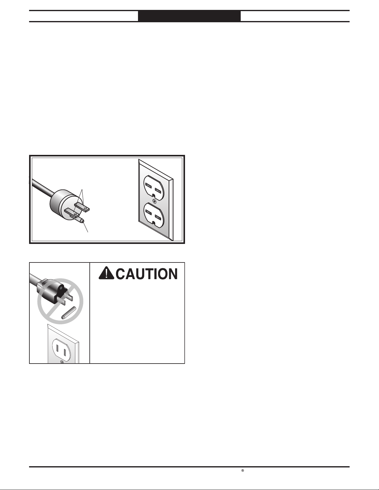
This machine is equipped with a power cord
that has
an equipment-grounding wire and a
grounding plug
(similar to the figure below).
The plug
must only be inserted into a matching
receptacle (outlet)
that is properly installed and
grounded in accordance with all local codes and
ordinances.
DO NOT modify the
included plug or use an
adapter if it will not fit your
receptacle. Instead, have a
qualified electrician install
the proper receptacle on a
power supply circuit that
is grounded and meets
the requirements for this
machine.
Improper connection of the equipment-grounding
wire can result in a risk of electric shock. The
wire with green insulation (with or without
yellow stripes) is the equipment-grounding wire.
If repair or replacement of the power cord or
plug is necessary, do not connect the equipment-
grounding wire to a live (current carrying)
terminal.
Check with an electrician or qualified service
personnel if you do not understand these
grounding requirements, or if you are in doubt
about whether the tool is properly grounded.
If you ever notice that a cord or plug is
damaged or worn, disconnect it from power, and
immediately replace it with a new one.
Extension Cords
Minimum Gauge Size............................16 AWG
Maximum Length (Shorter is Better) ....50 ft.
We do not recommend using an extension cord
with this machine. If you must use one, only
use it if absolutely necessary and only on a
temporary basis.
Extension cords cause voltage drop, which may
damage electrical components and shorten motor
life. Voltage drop increases as the extension cord
size gets longer and the gauge size gets smaller
(higher gauge numbers indicate smaller sizes).
Any extension cord used with this machine
must contain a ground wire, match the required
plug and receptacle listed in the
Circuit
Requirements
for the applicable voltage, and
meet the following requirements:
Grounding Prong
Current Carrying Prongs
6-15 PLUG
GROUNDED
6-15 RECEPTACLE
FigureFigure 7. NEMA 6-15 plug and receptacle.. NEMA 6-15 plug and receptacle.

South Bend Tools
For Machines Mfd. Since 11/21 Model SB1125
-13-
PREPARATION
Unpacking
This item was carefully packaged to prevent
damage during transport. If you discover any
damage, please immediately call Customer
Service at
(360) 734-1540 for advice. You may
need to file a freight claim, so save the containers
and all packing materials for possible inspection
by the carrier or its agent.
Inventory
NOTICE
If you cannot find an item on this list, carefully
check around/inside the machine and
packaging materials. Often, these items get
lost in packaging materials while unpacking or
they are pre-installed at the factory.
Wood Crate (Figure 8) Qty
A. Drill Press (not shown) ..................................1
B. Downfeed Handles .........................................3
C. Downfeed Levers............................................3
D. Table Height Crank Assembly ......................1
E. Arbor MT#3 x JT6.......................................... 1
F. Drill Chuck JT6 3⁄64"–5⁄8" ................................1
G. Drill Chuck Key ............................................. 1
H. Drift Key ........................................................ 1
I. Hex Wrench 5mm ..........................................1
J. Hex Wrench 4mm ......................................... 1
K. Hex Wrench 3mm ..........................................1
FigureFigure 8. Loose items inventory.. Loose items inventory.
BBCC
DD
EEFF
GG
HHII
JJKK

-14-
For Machines Mfd. Since 11/21
South Bend Tools
Model SB1125 PREPARATION
The unpainted surfaces are coated
at the factory
with a heavy-duty rust preventative that
prevents corrosion during shipment and
storage.
The benefit of this rust preventative is that it
works very well. The downside is that it
can be
time-consuming
to thoroughly remove.
Be patient and do a careful job when
cleaning
and removing the rust preventative
. The time
you spend doing this will reward you with
smooth
-sliding parts and a better appreciation
for the proper care of
the unpainted surfaces.
Although there are many ways to successfully
remove the rust preventative, the
following
process works well in most situations
.
Before cleaning, gather the following:
• Disposable
rags
• Cleaner/degreaser
(certain citrus-based
degreasers work extremely well and they
have non-toxic fumes)
• Safety glasses & disposable gloves
Note:
Automotive degreasers, mineral spirits, or
WD•40 can be used to remove rust preventative.
Before using these products, though, test them
on an inconspicuous area of a painted surface to
make sure they will not damage it.
Basic steps for removing rust preventative:
1. Put on safety glasses and disposable gloves.
2. Coat all surfaces that have rust preventative
with a liberal amount of your cleaner or
degreaser and let them soak for a few
minutes.
3. Wipe off the surfaces. If your cleaner or
degreaser is effective, the rust preventative
will wipe off easily.
Note: To clean off thick coats of rust
preventative on flat surfaces, such as beds
or tables, use a PLASTIC paint scraper to
scrape off the majority of the coating before
wiping it off with your rag. (Do not use a
metal scraper or it may scratch the surface.)
4. Repeat Steps 2–3 as necessary until clean,
then coat all unpainted surfaces with a
quality metal protectant or light oil to
prevent rust.
GAS
Gasoline and petroleum
products have low flash
points and can explode
or cause fire if used for
cleaning. Avoid using these
products to remove rust
preventative.
Many cleaning solvents are
toxic if inhaled. Minimize
your risk by only using
these products in a well
ventilated area.
Avoid chlorine-based solvents, such as
acetone or brake parts cleaner that may
damage painted surfaces. Always follow the
manufacturer’s instructions when using any
type of cleaning product.
T23692—Orange Power Degreaser
A great product for removing the waxy shipping
grease from the non-painted parts of the
machine during clean up.
Cleaning & Protecting
FigureFigure 9.. T23692 Orange Power Degreaser.

South Bend Tools
For Machines Mfd. Since 11/21 Model SB1125
-15-
PREPARATION
Min. 30"
Electrical
Connection
=
Wall
21½"
33"
Figure 10. Minimum working clearances.Figure 10. Minimum working clearances.
Physical Environment
Electrical Installation
Lighting
Weight Load
Space Allocation
Weight Load
Refer to the Machine Specifications for the
weight of your machine. Make sure that the
surface upon which the machine is placed will
bear the weight of the machine, additional
equipment that may be installed on the machine,
and the heaviest workpiece that will be used.
Additionally, consider the weight of the operator
and any dynamic loading that may occur when
operating the machine.
Space Allocation
Consider the largest size of workpiece that will
be processed through this machine and provide
enough space around the machine for adequate
operator material handling or the installation
of auxiliary equipment. With permanent
installations, leave enough space around
the machine to open or remove doors/covers
as required by the maintenance and service
described in this manual.
Physical Environment
The physical environment where your machine
is operated is important for safe operation and
longevity of
parts. For best results, operate this
machine in a dry environment that is free from
excessive moisture, hazardous
or flammable
chemicals, airborne abrasives, or extreme
conditions. Extreme conditions for this type
of machinery are generally those where the
ambient temperature
is outside the range of 41°–
104°F; the relative humidity
is outside the range
of
20–95% (non-condensing); or the environment
is subject to vibration, shocks, or bumps.
Electrical Installation
Place this machine near an existing power
source. Make sure all power cords are protected
from traffic, material handling, moisture,
chemicals, or other hazards. Make sure to leave
access to a means of disconnecting the power
source or engaging a lockout/tagout device.
Lighting
Lighting around the machine must be adequate
enough to perform operations safely. Shadows,
glare, or strobe effects that may distract or
impede the operator must be eliminated.
Children or untrained
people may be seriously
injured by this machine.
Only install in an access
restricted location.
Location

-16 -
For Machines Mfd. Since 11/21
South Bend Tools
Model SB1125 PREPARATION
Placing & Anchoring
Machine
Use a forklift to lift the machine off the pallet
and onto a suitable location, then secure the
machine to the shop floor.
This machine and its
parts are heavy! Serious
personal injury may occur
if safe moving methods are
not used. To reduce the
risk of a lifting or dropping
injury, ask others for help
and use power equipment.
To place machine:
1. Place shipping crate near final machine
mounting location.
2. Remove top and sides of crate from shipping
pallet.
3. Unbolt machine from pallet by removing
(4) hex nuts and fender washers shown in
Figure 11, and remove shipping support
braces.
Figure 11. Location of hex nuts and flat washers.Figure 11. Location of hex nuts and flat washers.
x 4
Placing Machine
4. Install table height crank assembly on table
height worm shaft, then tighten set screw to
secure (see Figure 12).
5. To help balance table when moving, loosen
table height lock handle shown in Figure
12, then use table height crank to lower
table as close to base as possible.
FigureFigure 12. Table height crank assembly installed on. Table height crank assembly installed on
table height worm shaft.table height worm shaft.
Table HeightTable Height
CrankCrank
AssemblyAssembly
Table HeightTable Height
LockLock
6. Tighten table height lock handle.
7. Place lifting sling around headstock (see
Figure 13), and attach sling securely to
forklift (or other power lifting equipment).
Figure 13. Lifting sling properly placed aroundFigure 13. Lifting sling properly placed around
headstock.headstock.

South Bend Tools
For Machines Mfd. Since 11/21 Model SB1125
-17-
PREPARATION
Anchoring to Concrete Floors
Note: Be sure sling does not put pressure on
belt cover or belt cover can become damaged
from force of sling while lifting.
8. Tighten all lock handles to keep moving
parts from shifting suddenly and
unbalancing machine.
9. With another person to help to steady
machine, lift machine just enough to clear
pallet and any floor obstacles, then place
machine in its final position in its final
position on shop floor.
Anchoring machinery to the floor prevents tip-
ping or shifting and reduces vibration that may
occur during operation, resulting in a machine
that runs slightly quieter and feels more solid.
If the machine will be installed in a commercial or
workplace setting, or if it is permanently connect-
ed (hardwired) to the power supply, local codes
may require that it be anchored to the floor.
If not required by any local codes, fastening the
machine to the floor is an optional step. If you
choose not to do this with your machine, we rec-
ommend placing it on machine mounts, as these
provide an easy method for leveling and they have
vibration-absorbing pads.
Number of Mounting Holes .............................4
Diameter of Mounting Hardware ...............5⁄16"
Figure 14. Popular method for anchoring machinery toFigure 14. Popular method for anchoring machinery to
a concrete floor.a concrete floor.
Lag shield anchors with lag screws (see below)
are a popular way to anchor machinery to a
concrete floor, because the anchors sit flush with
the floor surface, making it easy to unbolt and
move the machine later, if needed. However,
anytime local codes apply, you MUST follow the
anchoring methodology specified by the code.
Machine Base
Concrete
Lag Screw
Lag Shield Anchor
Flat Washer
Drilled Hole

-18-
For Machines Mfd. Since 11/21
South Bend Tools
Model SB1125 PREPARATION
Assembly
The machine must be fully assembled before it
can be operated. Before beginning the assembly
process, refer to Required for Setup on Page
10 and gather all listed items. To ensure the
assembly process goes smoothly, first clean any
parts that are covered or coated in heavy-duty
rust preventative (if applicable).
To assemble machine:
1. Thread (3) downfeed handles onto (3)
downfeed levers (see Figure 16).
Note: Lever end with notch should face away
from handle.
2. Thread (3) downfeed levers into hub on side
of headstock (see Figure 16).
x 3
HubHub
FigureFigure 16. Downfeed handles and levers installed.. Downfeed handles and levers installed.
Joining Drill Chuck
& Arbor
An arbor is included for the drill chuck that
comes with this machine. The following
procedure describes how to install the arbor in
the chuck.
After the arbor is installed in the drill chuck, it
is very difficult to separate the assembly. If you
would like to use a different chuck in the future,
we recommend obtaining a new arbor.
IMPORTANT:
DO NOT install the drill chuck and
arbor assembly into the spindle until AFTER the
test run.
To join drill chuck and arbor:
1.
Use acetone or lacquer thinner to clean drill
chuck and arbor mating surfaces, especially
the bore.
2.
Retract chuck jaws completely into chuck.
3.
Insert small end of arbor into chuck.
4.
Hold assembly by the arbor and tap chuck
onto a block of wood with medium force, as
illustrated below.
5. Attempt to separate drill chuck and arbor by
hand—if they separate, repeat Steps 3–4.
Figure 15. Joining drill chuck and arbor.Figure 15. Joining drill chuck and arbor.
Table of contents
Other South Bend Tools Power Tools manuals


