Southco EA-P3-200 User manual

EA-P3-200 High Frequency RFID Access
Controller Operating Instructions
J-EA-P3-200-M_revB Page 1 of 5
PRN: P2017-2297 (RJH/KAM)
1)Package Contents
•EA-P3-200 Proximity Reader
•Wire Harness
•Mounting Screws (x2)
•Operating Instructions
EA-P3-200 Proximity Reader
1. Status LED
2. Power LED
3. Loopback LED
Features
•LED and buzzer indicators
•Two operation modes:
oTimed mode with 10 user-selectable
operation times between 1-13s
oLatched mode
•Tamper switch
•Auxiliary Input
Specifications
Supply Voltage: 12VDC ± 10%
Supply Current: 160 mA maximum (no
attached devices)
Transmit Frequency: 13.56 MHz (ISO 14443A)
Card Reading Range: up to 5 cm (depending on
installation)
Operating Temperature: -15 to 55 °C
Dimensions: 94 mm x 43 mm x 15 mm
Note: Read range distance may vary depending on card
type, mounting conditions, or environmental conditions.
In some cases, the card may need to make contact with,
or be moved across, the RFID reader.
CAUTION: The High Frequency RFID Access
Controller PCA is an ESD-sensitive device. Observe ESD
best practices when accessing the PCA to avoid damage to
the PCA.
Reader Mounting and Installation
Please refer to Southco trade drawing J-EA-P3-200 for
mounting and installation details.
Wire Descriptions
The EA-P3-200 has a 12-wire stripped and tinned harness,
as described below:
Color
Description
Red +12 VDC
Black GND
Brown Relay N.O.
Orange Relay COM
Yellow Relay N.C.
Green No function (cut this wire)
Blue Auxiliary Input
Light Green Loopback LED GND
Pink Loopback LED Control (+12 VDC)
Purple Tamper Switch N.C.
Gray Tamper Switch N.O.
White Tamper Switch COM
An example connection diagram is shown below.
Default Settings
Operation Mode: Timed Mode
Default Access Time: Approximately 5 seconds
Set Up
1. Choose operation mode, timed or latched, using
the jumper settings shown in section “Operation
Mode Change”. The default setting is timed mode.
See sections “Timed Mode Use” and “Latched
Mode Use” for specific details on each mode.
2. Apply power to unit.
Supervisor Card Setup
3. Hold down SW1 for at least 10 seconds. This will
clear the reader memory of all cards. During this
time, the unit will beep once after approximately 2
EA-P3-200 High Frequency RFID Access
Controller Operating Instructions
J-EA-P3-200-M_revB Page 2 of 5
PRN: P2017-2297 (RJH/KAM)
seconds, and again after approximately 10
seconds. This will indicate that the operation has
been completed. Release SW1.
4. Hold down SW1 for 2 seconds. The unit will beep
once. Release SW1.
5. Present a card to be made the “supervisor” card
within 3 seconds.
a. Note: Any card can be promoted to
supervisor by repeating steps 4 and 5.
b. Note: Only one supervisor card may be
active at a time.
c. Note: Supervisor cards cannot be used
to activate the relay.
6. Remove the supervisor card from the reader.
User Card Setup
7. Present the supervisor card to the reader.
8. The green LED will flash, indicating that a “user”
card may be enrolled.
9. After the user card is presented to the reader, the
green LED will go out.
a. Note: No cards may be deleted, other
than by using Step 3.
b. Up to 64 user cards may be enrolled by
repeating steps 7 and 8, after which
performing Step 7 will result in three
short beeps, indicating that no more
cards may be enrolled.
c. Note: Only a user card can be used to
activate the relay.
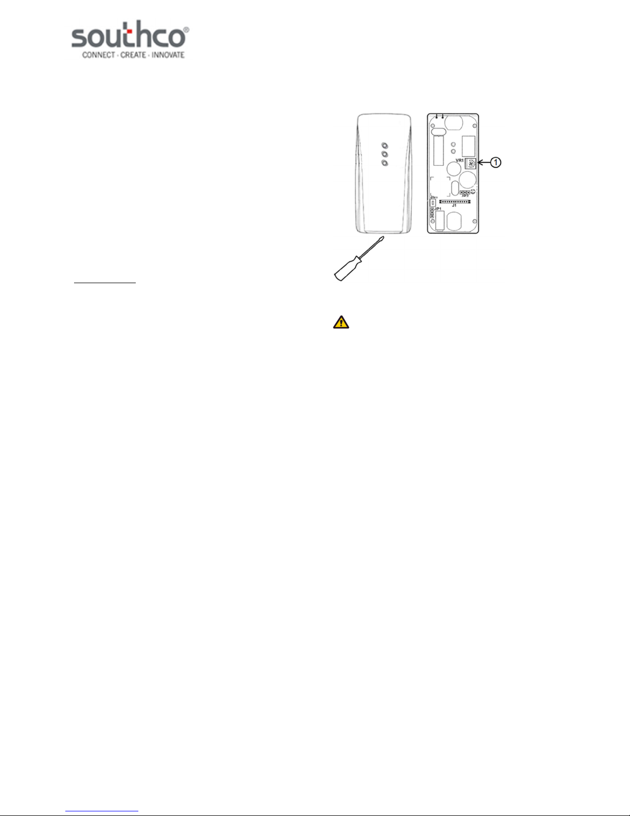
Timed Mode Use
1. Set the desired relay active time using VR1 (see
illustration below).
a. To access VR1, remove the cover from
the unit using a flathead screwdriver to
pry the cover off.
b. Use a Phillips screwdriver to turn the
dial on VR1 to adjust the relay active
time: clockwise to lengthen the time,
counter-clockwise to shorten the time.
2. When a user card is presented to the reader, the
relay will activate for the time set on VR1, then de-
activate automatically. The unit will beep once
when the relay activates.
1. VR1
CAUTION: The High Frequency RFID Access
Controller PCA is an ESD-sensitive device. Observe ESD
best practices when accessing the PCA to avoid damage to
the PCA.
Latched Mode Use
When a user card is presented to the reader, the relay will
switch state from inactive to active, until a user card is again
presented to the reader. The unit will beep once each time.
Unauthorized Card Use
When an unenrolled card is presented to the unit, the unit
will beep twice, indicating that the card is unenrolled.

EA-P3-200 High Frequency RFID Access
Controller Operating Instructions
J-EA-P3-200-M_revB Page 3 of 5
PRN: P2017-2297 (RJH/KAM)
Operation Mode Change
This product uses jumpers to configure its operation mode.
To access the jumpers on this product, use a flathead
screwdriver on the slot in the housing and pry to remove the
cover. See the installation directions in J-EA-P3-200 for
details.
1. SW1
2. JP1
3. JP2
CAUTION: The High Frequency RFID Access
Controller PCA is an ESD-sensitive device. Observe ESD
best practices when accessing the PCA to avoid damage to
the PCA.
Timed Mode Latched Mode
JP1
JP2
Note: Controller is set for timed mode by default
Tamper Switch
This unit is equipped with a switch that opens when the
cover is removed from the unit. The status of the switch can
be sensed between the white wire (Tamper Switch COM)
and either the purple wire (Tamper Switch N.C.) or gray wire
(Tamper Switch N.O.). The switch logic is as follows:
1. White-Gray: When the cover is closed, this circuit
is closed. When the cover is open, this circuit is
open.
2. White-Purple: When the cover is closed, this
circuit is open. When the cover is open, this circuit
is closed.
An example connection diagram with a +12 VDC audible
alarm is shown below.
NOTE: Southco does not supply audible alarms.
EA-P3-200 High Frequency RFID Access
Controller Operating Instructions
J-EA-P3-200-M_revB Page 4 of 5
PRN: P2017-2297 (RJH/KAM)
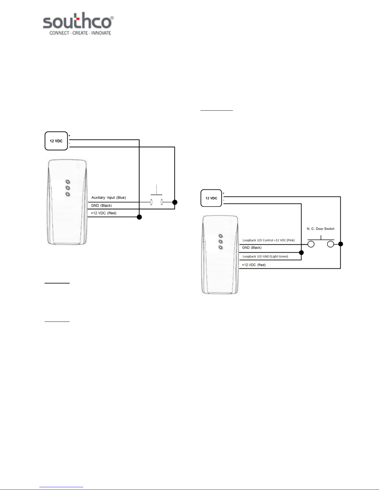
Auxiliary Input
This unit is equipped with an Auxiliary Input function. When
the Auxiliary Input wire (Blue) is connected to GND (Black), it
has the same effect as a user card being presented to the
unit (see Timed Mode Use and Latched Mode Use). An
example Auxiliary Input circuit is illustrated below.
NOTE: Southco does not supply Auxiliary Input switches.
LED Behavior
The EA-P3-200 has three LEDs to indicate status.
Power LED
When power is first applied to the reader, the Power LED will
turn solid orange. It will remain orange as long as power is
supplied.
Status LED
When a credential is presented to the reader, the Status
LED will turn green. It will then do the following based on the
status of the credential presented:
Supervisor card – the LED will flash for
approximately three seconds, indicating the unit is ready to
enroll a new user card
User card – the LED will flash once upon granting
access
Unenrolled MIFARE card – the LED will remain
solid for approximately three seconds
The status LED will also light up when SW1 is pressed, and
will remain on as long as it is held down.
Loopback LED
When +12 VDC is applied between the Loopback LED
Control (+12 VDC) (Pink) and Loopback LED GND (Light
Green) wires, the Loopback LED will light up red as long as
voltage continues to be applied. If paired with a normally
closed door switch (N.C. Door Switch), the Loopback LED
can be used to indicate whether the door controlled by the
Access Controller is open or closed. An example circuit is
given below.
NOTE: Southco does not supply door switches.
Compatible Card types
The following MIFARE card types are compatible with this
unit:
MIFARE Classic MIFARE Ultralight, MIFARE DESFire EV1,
MIFARE Plus, MIFARE with 7B UID, HID MIFARE, HID
MIFARE DESFire EV1
Southco offers the following Part Numbers that are
compatible with this unit: EA-C3-101-9, EA-C3-300-9

EA-P3-200 High Frequency RFID Access
Controller Operating Instructions
J-EA-P3-200-M_revB Page 5 of 5
PRN: P2017-2297 (RJH/KAM)
FCC Compliance Statement
This device complies with Part 15 of the FCC Rules. Operation is subject to the following two conditions:
1) This device may not cause harmful interference, and
2) This device must accept any interference received, including interference that may cause undesired operation.
This equipment has been tested and found to comply with the limits for a Class B digital device, pursuant to Part 15 of the FCC Rules. These limits
are designed to provide reasonable protection against harmful interference in a residential installation.
This equipment generates, uses and can radiate radio frequency energy and, if not installed and used in accordance with the instructions, may cause
harmful interference to radio communications. However, there is no guarantee that interference will not occur in a particular installation. If this
equipment does cause harmful interference to radio or television reception, which can be determined by turning the equipment off and on, the user is
encouraged to try to correct the interference by one of the following measures:
• Reorient or relocate the receiving antenna.
• Increase the separation between the equipment and receiver.
• Connect the equipment into an outlet on a circuit different from that to which the receiver is connected.
• Consult the dealer or an experienced radio/TV technician for help.
FCC Caution: To assure continued compliance, any changes or modifications not expressly approved by the party responsible for compliance could
void the user's authority to operate this equipment. (Example - use only shielded interface cables when connecting to computer or peripheral devices).
Industry Canada Compliance Statement
This device complies with Industry Canada licence-exempt RSS standard(s). Operation is subject to the following two conditions:
1) this device may not cause interference, and
2) this device must accept any interference, including interference that may cause undesired operation of the device.
Le présent appareil est conforme aux CNR d’Industrie Canada applicables aux appareils radio exempts de licence. L’exploitation est autorisée aux
deux conditions suivantes:
1) l’appareil ne doit pas produire de brouillage, et
2) l’utilisateur de l’appareil doit accepter tout brouillage radioélectrique subi, même si le brouillage est susceptible d’en compromettre le
fonctionnement.
Trademark Statements
MIFARE, MIFARE Classic, MIFARE Ultralight, MIFARE DESFire EV1 and MIFARE Plus are trademarks of NXP B.V.
HID is a registered trademark of HID Global
Other Southco Controllers manuals


