Dynojet Power commander V User manual

2012 Arctic Cat 1100 Turbo PCV - 1I11-009 www.powercommander.com
Installation Instructions
PLEASE READ ALL DIRECTIONS BEFORE STARTING INSTALLATION
THE IGNITION MUST BE TURNED
OFF BEFORE INSTALLATION!
YOU CAN ALSO DOWNLOAD THE
POWER COMMANDER SOFTWARE AND
LATEST MAPS FROM OUR WEB SITE AT:
www.powercommander.com
2191 Mendenhall Drive North Las Vegas, NV 89081 (800) 992-4993 www.powercommander.com
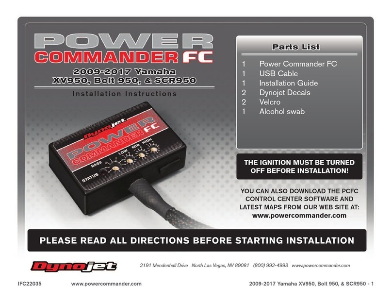
PARTS LIST
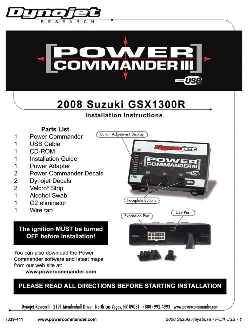
1 Power Commander
1 USB Cable
1 CD-ROM
1 Installation Guide
2 Power Commander Decals
2 Dynojet Decals
2 Velcro Strip
1 Alcohol Swab
3 Zip Tie
2012 Arctic Cat 1100 Turbo
Fuel Controller

I11-009 www.powercommander.com 2012 Arctic Cat 1100 Turbo PCV - 2
EXPANSION PORTS 1 & 2
Optional Accessories such as
Color LCD unit or Auto tune kit.
POWER COMMANDER V
INPUT ACCESSORY GUIDE
Map- The PCV has the ability to hold two different
base maps. You can switch on the fly between
these two base maps when you connect
a switch to the MAP inputs. You can use
any open/close type switch. The polarity of
the wires is not important. When using the
Autotune kit, one position will hold a base map
and the other position will let you activate the
learning mode. When the switch is “CLOSED”
Autotune will be activated.
Shifter- Not used for snowmobiles.
Speed- If your application has a speed sensor then
you can tap into the signal side of the sensor
and run a wire into this input. This will allow
you to calculate gear position in the Control
Center Software. Once gear position is setup
you can alter your map based on gear position
and setup gear dependent kill times when
using a quickshifter.
Analog- This input is for a 0-5v signal such as
engine temp, boost, etc. Once this input
is established you can alter your fuel curve
based on this input in the control center
software.
Crank- Do NOT connect anything to this port unless
instructed to do so by Dynojet. It is used to
transfer crank trigger data from one module to
another.
ACCESSORY INPUTS
PCV Wire Connections
1. Remove the rubber plug on the backside of the
unit and loosen the screw for the corresponding
input.
2. Using a 22-24 gauge wire, strip about 10mm
from its end.
3. Push the wire into the hole of the PCV until it
stops and then tighten the screw.
4. Make sure to reinstall the rubber plug.
Note: If you tin the wires with solder it will make
inserting them easier.
CRANK
ANALOG
SPEED
MAP
MAP
SHIFTER
SHIFTER
USB CONNECTION

I11-009 www.powercommander.com 2012 Arctic Cat 1100 Turbo PCV - 3
1 Remove both side panels by pulling out the split cotter pins and pivoting the
panels rearward out of the hinge points.
2 With the side panels removed, remove the torx head screw securing the hood
to the cowling on both sides of the snowmobile.
3 Unscrew the two torx screws underneath the front of the snowmobile.
These screws are recessed above the skid plate and accessible through two
access holes.
FIG.A
FIG.C
FIG.B

I11-009 www.powercommander.com 2012 Arctic Cat 1100 Turbo PCV - 4
4 Pop the air intake box away from the tube on the left side of the snowmobile.
5 Unplug the hood harness connector located below the display gauge.
6 Remove the hood and set it aside.
7 Unscrew the gas cap and cowling retaining nut.
8 Remove the torx screws on each side of the steering column holding the tank
shroud.
FIG.D
FIG.F
FIG.E

I11-009 www.powercommander.com 2012 Arctic Cat 1100 Turbo PCV - 5
9 Pull rearward on the cowling allowing the tank shroud to pop loose above it.
10 Lift the tank shroud off the gas filler neck taking care to unplug the spade
connectors for the reverse beeper.
11 Using the supplied velcro, secure the PCV to the top of the stock ECU as
shown in Figure H.
Make sure to clean both surfaces with the alcohol swab before attaching.
12 Allowing the wire harness to loop rearward on the machine and then come
forward, route the injector leg of the harness down the left side of the engine
on top of the clutch guard as shown in Figure H.
13 Locate and unplug the 6-pin connector on top of the clutch guard as shown in
Figure I.
FIG.G
FIG.H
FIG.I
PCV harness

I11-009 www.powercommander.com 2012 Arctic Cat 1100 Turbo PCV - 6
14 Attach the injector connector from the PCV harness to the stock injector
connectors as shown in Figure J.
Verify these connections are pushed down amongst the stock harness so the
side panel cooling vent can be slid over the top into its factory location.
15 Remove the fuse box cover on top of the clutch guard. This allows access to
the nut shown in Figure K.
16 Remove the nut.
17 Attach the ground lug from the PCV harness to the bolt.
18 Retighten the nut.
19 Route the other leg of the of the harness upward near the intake manifold.
20 Locate and unplug the TPS sensor.
FIG.L
FIG.K
FIG.J

I11-009 www.powercommander.com 2012 Arctic Cat 1100 Turbo PCV - 7
21 Attach the TPS connector from the PCV harness to the stock TPS connectors.
22 Locate the MAP sensor connector.
The MAP sensor connector is located on the
manifold slightly rearward of the TPS connector.
23 Using the supplied posi-tap, attach the grey/white
wire from the PCV harness to the green/tan wire
on the stock MAP sensor.
24 Route the last leg of the PCV harness up and over the intake manifold to the
right hand side of the snowmobile.
25 Unplug the 2-pin crank sensor connector.
This connector is located inward of the exhaust silencer along the engine.
FIG.O
FIG.N
FIG.M

I11-009 www.powercommander.com 2012 Arctic Cat 1100 Turbo PCV - 8
26 Attach the crank sensor connector from the PCV harness to the stock crank
sensor connectors.
27 Using the supplied zip ties, secure all wires away from any hot engine
components.
28 Replace all shrouds, panels, screws, and wire connections.
29 Insert the CD provided into your computer. Follow the on-screen instructions
to install the PCV software.
Visit www.powercommander.com to download software tutorials.
EFI Tuning with PCV
The Power Commander makes fueling changes off of the numbers in the map stored in the Power Commander. The snowmobile Power Commanders
are shipped with a Zero Map. With a Zero Map, the snowmobile will run the stock fueling programmed in the ECU. When a map is loaded into the
Power Commander, the snowmobile will be fueled according to the numbers in the map. The Power Commander does not make changes to the ECU
programming.
The numbers in the Power Commander map add or subtract a percentage of the fuel the ECU is supplying for a particular load condition. For example,
if the Power Commander map shows a 10 in a given cell, the Power Commander increases the amount of fuel the ECU is supplying by 10%. If the
Power Commander map shows a -10 in a given cell, the Power Commander reduces the amount of fuel the ECU is supplying by 10%.
When tuning, always start with a setting where the motor runs rich. Slowly trim fuel out to find the desired exhaust gas temperature (EGT) or air-to-fuel
ratio (A/F).
The PCV gives you the freedom to subtract up to 99% and add up to 250% of the fuel the ECU is supplying for a particular condition. When adding
fuel with the Power Commander, the injector duty cycle may reach 100% (always open) before the Power Commander value reaches 100%. For
example, if the ECU is running the injectors at 67% duty cycle (injectors open 67% of the time) then adding 50% fuel with the Power Commander will
max out the injectors. In this case, the amount of fuel that can be added will be limited by the injectors.
Fuel Subtraction
The PCV gives you the ability to trim fuel out of the map to correct rich conditions.
Caution: Engine failure can result from running the engine in a lean state.
FIG.P

I11-009 www.powercommander.com 2012 Arctic Cat 1100 Turbo PCV - 9
Additional Features and Accessories for the Power Commander V
The PCV can be combined with the Dynojet Autotune kit (P/N AT-200) allowing you
to tune as you ride. The Autotune feature uses a target AFR table where the user
specifies a target AFR based on TP and RPM. After enabling Autotune, the user
rides as normal and the PCV calculates a trim table as you ride. Once the system
has calculated a trim table for the specified conditions, the user can accept the trims
as a base map and turn the Autotune feature off.
Autotune is a very powerful feature allowing the user to build custom maps for
any modifications made to the sled, including big bore kits, aftermarket pipes, and
intakes. The Autotune kit may also be used to smooth out a stock sleds fuel map
eliminating midrange flat spots and improving throttle response.
If you are looking for a display for your setup we have the answer. Dynojet’s LCD-
200 is a color touch screen display capable of displaying all PC data and AFR if you
are using the Wideband 2. The LCD-200 is capable of logging data including TP,
RPM, Injector duty cycle, fuel change, AFR, and two analog signals input into the
PCV.
The LCD-200 uses a standard SD card (1GB or smaller) to store data. The data
logged on the LCD-200 can be played back in the field or downloaded to your
computer and viewed in Excel.
FIG.R
FIG.Q
Other manuals for Power commander V
95
Table of contents
Other Dynojet Controllers manuals
Popular Controllers manuals by other brands

TC Electronic
TC Electronic TC ICON Series user manual

Pixsys
Pixsys DRR460 Series user manual

Carlisle
Carlisle Ransburg Service manual

Supreme Heating
Supreme Heating Aqua-Gen 3BR Installation instructions manual

Balboa Water Group
Balboa Water Group HydroAir 20-0344 manual

Festo
Festo CMMO-ST-C5-1-DIOP Original instructions

Integra
Integra DHC-80.2 instruction manual

Ryobi
Ryobi One+ Easy Starter Original instructions

Resol
Resol DeltaSol CS Plus manual

Johnson Controls
Johnson Controls VA-8122 Technical bulletin

Pressure Tech
Pressure Tech LF-540 Series Operating and service manual

Pneumatic Division
Pneumatic Division 05E Installation & service instructions