Southern Pride SRG-400 User manual

1 of 38 Copyright 2015 by Southern Pride Distributing, LLC Volume 1
401 South Mill Street , Alamo, Tennessee 38001 731-696-3175 http://www.southern-pride.com
OWNER’S MANUAL
Gas-Fired Wood-Burning
Stationary Rack BBQ Smoker
Southern Pride smokers have been tested and approved by Intertek Testing Services,
and are ETL listed to ANSI Z83.11b - 2009, CSA 1.8b - 2009,
and to NSF/ANSI Standard 4.
ETL File Number 4007026

2 of 38 Copyright 2015 by Southern Pride Distributing, LLC Volume 1
Southern Pride smokers are gas-fired, wood-burning, ETL listed, commercial cooking appliances whose
installation, operation, and maintenance should comply with the instructions in this manual, NFPA® 96
and other codes and standards as called out in this manual. For more information on NFPA® 96, or to
obtain a copy of the latest publication, please contact:
NFPA®
1 Batterymarch Park
PO Box 9101
Quincy, MA 02169-7471
www.nfpa.org

3 of 38 Copyright 2015 by Southern Pride Distributing, LLC Volume 1
CONGRATULATIONS!
In selecting Southern Pride, you have chosen the finest, most advanced
and most fully automatic wood burning barbecue smoker available.
With us, “ It’s Simply, a Matter of Pride”.
Please read this Manual carefully prior to installation, operation and maintenance of
your Southern Pride smoker. Proper installation, operation, and maintenance are essen-
tial for your satisfaction and safe operation.
KEEPTHIS MANUAL FOR REFERENCE
NOTE: An Electrical Diagram for this appliance can be found on the inside of the service access panel.
This smoker may be operated outdoors.

4 of 38 Copyright 2015 by Southern Pride Distributing, LLC Volume 1
TABLE OF CONTENTS
Safety Information and Precautions...................................................................5
Diagram of Controls & Components.............................................................. 6-7
INSTALLATION
Receiving the Smoker...........................................................................................8
Delivery Location..................................................................................................8
Unloading the Smoker..........................................................................................9
Unpacking the Smoker.........................................................................................9
Site Instructions ...................................................................................................9
Electrical Instructions........................................................................................10
Gas Piping Instructions................................................................................ 11-13
Gas Connection Instructions.............................................................................14
Installation Instructions for Restraining Device .............................................15
Burner Specification...........................................................................................16
Venting Instructions...........................................................................................17
OPERATION
Product Loading Instructions ...........................................................................18
Firebox Loading Instructions............................................................................19
Control Operating Instructions...................................................................20-22
Product Unloading Instructions........................................................................23
Ash Removal Instructions..................................................................................23
Grease Removal Instructions ............................................................................24
Wood Storage Instructions................................................................................24
Mobile Smoker Operation.................................................................................25
Mobile Smoker Electrical Information ............................................................25
Mobile Smoker Warnings............................................................................25-27
MAINTENANCE
Daily.....................................................................................................................28
Weekly...........................................................................................................28-29
Monthly .........................................................................................................30-31
Quarterly/Semi-Annually..................................................................................31
As Needed......................................................................................................32-33
Wiring Diagram..................................................................................................34
Replacement Parts List......................................................................................35
Before You Call For Service..............................................................................36
Troubleshooting the Gas Burner ......................................................................37
Limited Warranty ..............................................................................................38

5 of 38 Copyright 2015 by Southern Pride Distributing, LLC Volume 1
SAFETY INFORMATION AND PRECAUTIONS
WARNING:
FOR YOUR SAFETY
IF YOU SMELL GAS…...
1. Open windows
2. Do not touch electrical switches
3. Extinguish any open flames
4. Immediately call your gas supplier
DANGER:
Do not store or use gasoline or other
flammable vapors or liquids in the
vicinity of this or any other appliances.
DANGER:
Improper installation, alteration, adjustment, service, or maintenance could result in severe
injury, death, or cause property damage. Read the installation, operating, and maintenance
instructions thoroughly before installing or servicing this equipment.
1. IT IS EXTREMELY IMPORTANT TO FOLLOW THE PRESCRIBED CLEANING INSTRUCTIONS.
GREASE OR SOLIDS BUILDUP INSIDE THE SMOKER COULD RESULT IN A FIRE HAZARD.
2. This smoker is intended for use in commercial facilities where all operators are familiar with the purpose,
limitations, and associated hazards of this equipment. The operating instructions and warnings must be read and
understood by all operators and users.
3. This manual and all supplied instructions, diagrams, schematics, parts lists, notices and labels must remain with the
smoker even if the smoker is sold or moved to another location.
4. The area around the smoker MUST be kept clear and free of combustible materials, gasoline and other flammable
vapors and liquids.
5. The flow of combustion and ventilating air MUST NOT be obstructed from reaching the smoker.
6. The frame of the smoker MUST be electrically grounded at all times. See “Electrical instructions”.
7. Caution should be used when opening and closing the firebox door. The door is HOT during operation.
8. DO NOT remove service compartment access panels when smoker is in operation or leave off during operation.
9. Gas burners require the services of a qualified service technician for proper setting and adjustment. If the burner does
not appear to be operating properly, DO NOT ATTEMPT TO ADJUST THE BURNER YOURSELF.
10. DO NOT allow unqualified personnel to perform service work or adjustments on this smoker. Doing so, will VOID
WARRANTY and could result in a hazardous condition.
11. Ensure new employees, who might operate the smoker, are properly instructed and supervised on the operation and
safety information prior to operating the smoker.
12. Ashes removed from the firebox should be stored in a non-combustible container with a sealed lid only. Store ashes
in a well ventilated area. FUMES COULD BE HAZARDOUS.
This Manual should be considered a permanent part of this smoker. THE SMOKER MUST BE INSTALLED
BY A QUALIFIED SERVICE TECHNICIAN. All troubleshooting guides, component views and parts lists
included in this manual are for general reference only and are intended for use by qualified technical personnel.
CAUTION:
Metal parts and surfaces of this smoker
become extremely hot when in operation.
To avoid burns, always use hand
protection when operating the smoker.
WARNING:
CARBON MONOXIDE
POISONING HAZARD
Carbon monoxide is a colorless, odorless gas that can
kill. Follow these rules to control carbon monoxide.
Do not use the smoker if in an unvented, enclosed
area. Carbon monoxide may accumulate.
Allow only qualified burner service persons to ad-
just the burner. Special instruments and training
are required.
Read the owner’s manual before using.
WARNING:
ELECTRIC SHOCK HAZARD
Follow these rules to avoid electric shock.
Use only a properly grounded circuit.
Do not spray water directly on electrical compo-
nents.
Turn off power before servicing.

6 of 38 Copyright 2015 by Southern Pride Distributing, LLC Volume 1
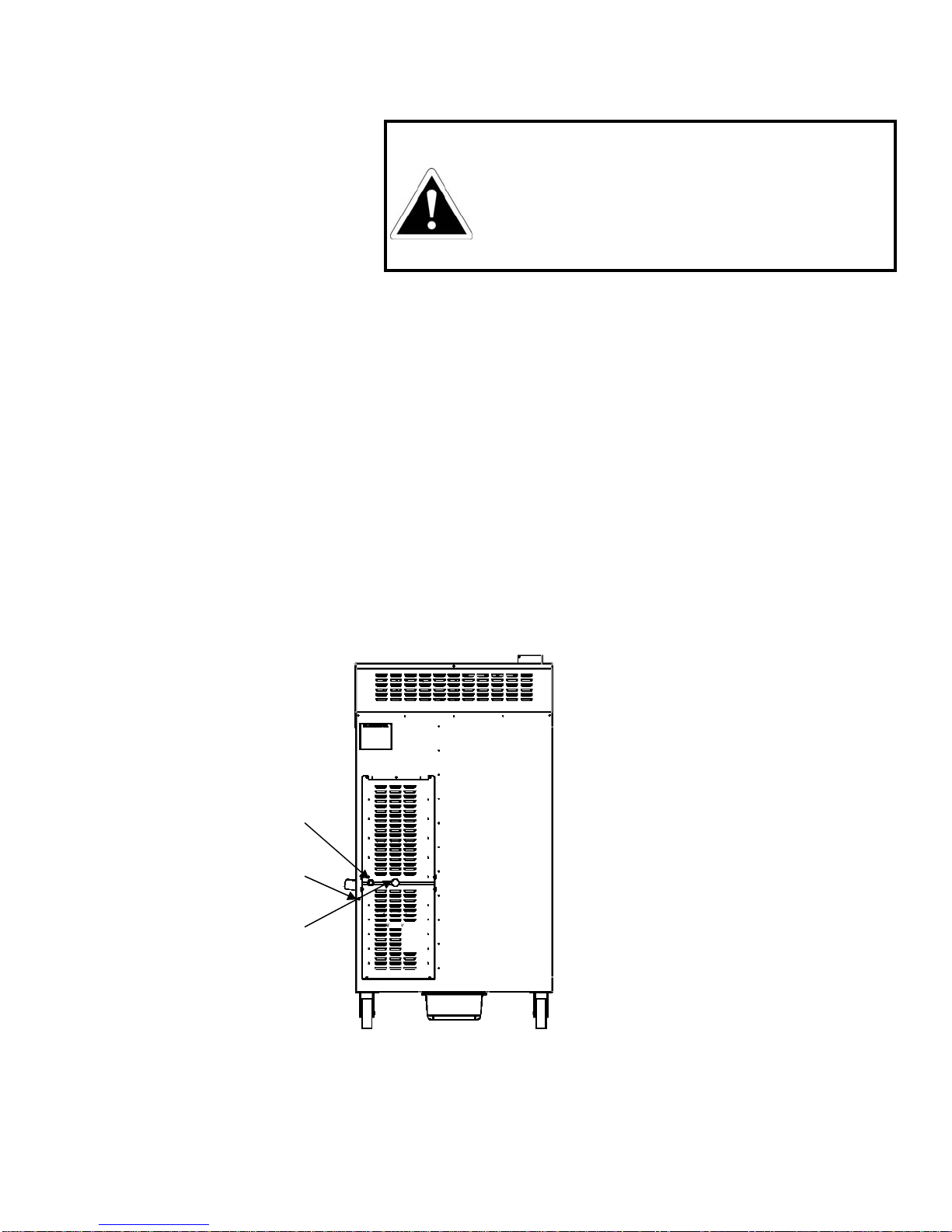
DIAGRAM OF CONTROLSAND COMPONENTS
Front View Rear View
Left Side View Right Side View
Top View
2
3
4
5
6
7
8
9
10
11
1
13
12

7 of 38 Copyright 2015 by Southern Pride Distributing, LLC Volume 1
DIAGRAM OF CONTROLAND COMPONENTS
1. DIGITAL COOK & HOLD CONTROL - Provides precise temperature control of the smoker along with control of the other
functions of the smoker.
2. FLUE - Designed for use with Type-1 Canopy hood.
3. GREASE DRAIN PAN – Opening in bottom of smoker allows grease to drain from Smoker into pan during the cook cycle.
Pan must be emptied after each cook cycle.
4. FIREBOX DOOR - Provides access to the firebox chamber for loading wood and ash removal. Keep closed while cooking.
5. 6” LOCKING CASTER WHEELS - Heavy duty locking casters provide a solid base and offers convenient mobility.
6. DATA PLATE - Label containing smoker’s serial number, model number, manufactured date, etc.
7. CONTROL / FAN MOTOR COMPARTMENT – Location of the convection fan motor, control module and relay board.
8. SERVICE COMPARTMENT COVER - Access to service bay where burner is located.
9. PRODUCT LOADING DOOR – Provides access to load/unload product and for cleaning the interior of the smoker.
10. PRODUCT LOADING DOOR LATCHES - Latches apply positive pressure and seals doors.
11. GAS SUPPLY CONNECTION - Drip leg connection point for incoming gas supply to smoker.
12. POWER CORD CONNECTION - Access point for supply power cord to smoker.
13. TETHER / WALL ANCHOR BOLT MOUNTING LOCATION - Threaded hole for installation of eyelet bolt used to attach
restraining device for smokers mounted on caster wheels to guard against transmission of strain to the gas and electrical connec-
tions. Required by ANSI Z83.11b - 2009.

8 of 38 Copyright 2015 by Southern Pride Distributing, LLC Volume 1
INSTALLATION
RECEIVING THE SMOKER
Your smoker can be shipped via a contract hauler on a flatbed trailer, or Common Carrier. Once the smoker
arrives you will need a forklift to remove the crated smoker from the truck (Common Carrier deliveries).
NOTE: The above weights are for the base model only.
DELIVERY LOCATION
Commercial smokers are large and heavy. Before scheduling the delivery of your smoker have a plan and lo-
cation in place to accept the delivery of the smoker and maneuver the smoker into the desired installation loca-
tion. The trucker will require a flat, level surface that is safe from traffic to unload the smoker. A forklift will
be required to unload the smoker. The trucker is only responsible for delivery of the smoker. It is your re-
sponsibility to unpack the smoker, move it to its installation location, and install the smoker.
Model Approx. Wt.
Uncrated Approx. Wt.
Crated
SRG-400 780 lb. 1,005 lb.
WARNING:
If the forklift forks are not long enough to support the entire smoker/crate do not attempt
to move the smoker; obtain another forklift or use fork extensions.
WARNING:
Only proper heavy lifting machinery and heavy lifting equipment should be used for
unloading, moving and installing the smoker. This duty should only be performed by
professionals trained in this kind of work. Improper handling of the equipment could
result in damaging the smoker or personal injury and even death.

9 of 38 Copyright 2015 by Southern Pride Distributing, LLC Volume 1
UNLOADING THE SMOKER
Smokers Shipped via Common Carrier
Remove the crated smoker from the truck using the appropriate forklift. Note any damage to the crate, smoker
or accessories. Do not sign the delivery bill until the smoker has been inspected and any damage noted
on the delivery bill.
The smoker is shipped strapped to a wooden pallet with an industrial cardboard carton. Once the smoker is in
a level and safe place remove the cardboard carton and open the product loading door. Plastic zip ties secure a
cardboard box to one of the product racks of the smoker. Remove the cardboard box from the product rack.
Cardboard covers protect each product rack during shipment. Remove the cardboard protectors from each
product rack. Located on top of the wooden pallet are two (2) wooden ramps. Fasten the ramps to the edge of
the wooden pallet using the metal clasps located on the end of the pallet and ramps. The smoker is secured to
the wooden pallet with metal banding straps. After removing the banding straps securing the smoker to the
wooden pallet, release the brakes on each of the smokers casters. Then the smoker can be slowly and carefully
rolled down the ramps secured to the pallet.
Smokers Shipped via Contract Hauler
The driver will unload the smoker from the trailer. Once the smoker is in a level and safe place remove the
white protective wrap from the outside of the smoker and open the product loading door. Plastic zip ties se-
cure a cardboard box to one of the product racks of the smoker. Remove the cardboard box from the product
rack. Cardboard covers protect each product rack during shipment. Remove the cardboard protectors from
each product rack.
UNPACKING THE SMOKER
The cardboard box inside the smoker contains the following items:
Sample seasoning and sauces. Bulk sizes are available. Please contact your authorized Southern Pride dis-
tributor for additional information.
Restraining device.
SITE INSTRUCTIONS
The Southern Pride smoker must be installed in a location that will permit the smoker to function for its in-
tended purpose and to allow adequate clearance for ventilation, proper cleaning, and maintenance access.
Minimum Clearance Requirement from Combustible Material
Back…...18” (457mm) Front…………….……...48” (1219mm)
Top…….18” (457mm) Right & Left Side...……...2” (51mm)
NOTE: If provision is made for service access, back clearance can be
reduced to 2” (51mm).
WARNING: Failure to maintain proper safety, storage, handling, and ash removal for solid fuel
appliances on or around combustible materials may result in fire, property damage and/or death.
Our product listing allows for the smoker to be installed on a combustible surface however,
Southern Pride recommends the use of a noncombustible material for the floor surface area under
the fire box, which should extend at least 6” beyond each side of the fire box, and outward from
the smoker beyond the area needed for placement of the ash container.
10 of 38 Copyright 2015 by Southern Pride Distributing, LLC Volume 1
INSTALLATION INSTRUCTIONS
ELECTRICALINSTRUCTIONS
Electrical Requirements:
120 volts AC, 60 Hz
2 wire, single phase
15 amp required, NEMA 5-15P plug
THE WARRANTY IS VOID IF THE SMOKER IS CONNECTED TO ANY VOLTAGE OTHER
THAN SPECIFIED ABOVE AND ON THE SMOKER DATA PLATE.
Remove all packing material before connecting the electrical and gas supply to the smoker.
An electrician must provide the conduit and wire for electrical hookup. The smoker should be connected
to a dedicated 15 amp receptacle.
The power is to be left OFF throughout the installation.
The electrical service is connected via the factory supplied power cord normally located to the rear of the
smoker on the service bay side. Alternatively, the power cord can be removed and the smoker hard wired.
5. If venting or gas connections are to be done at a later time, be sure that the power remains OFF.
6. The restraining device must be installed.
WARNING:
This appliance, when installed, must be electrically
grounded in accordance with local codes, or in the
absence of local codes, with the National Electrical
Code, ANSI/NFPA 70, or the Canadian Electrical
Code, CSA C22.2, as applicable.
Electrical Connection
Tether Connection
Gas Supply Connection

11 of 38 Copyright 2015 by Southern Pride Distributing, LLC Volume 1
GAS PIPING INSTRUCTIONS
IMPORTANT NOTES TO THE INSTALLER
Read all instructions contained in this Owner’s Manual before making gas connections.
Ensure all packing material is removed from the smoker compartments before connecting the gas supply to
the smoker.
Be sure your smoker is installed and grounded properly by a qualified service technician.
Observe all governing codes and ordinances.
WARNING: IMPROPER GAS HOOKUP WILL VOID WARRANTY AND COULD RESULT IN A
HAZARDOUS CONDITION.
1. All local and national codes and ordinances must be observed. Installation must conform with local codes
or in the absence of codes, the National Fuel Gas Code ANSI Z223.1 / NFPA-54, latest edition available
from The American Gas Association, Inc., 1515 Wilson Boulevard, Arlington, VA 22209.
2. The gas supply (service) line must be the same size or greater than the inlet line of the appliance. This
smoker uses a 1/2” (1.3 cm) ID NPT (Sch40) inlet. Sealant on all pipe joints must be resistive to LP gas.
3. Supply line and manifold pressure should be checked with a manometer. Refer to page 16 for minimum
and maximum pressures. Incoming line pressure upstream from the regulator must be 1” W.C.P. higher
than the manifold pressure in order to check the regulator. The regulator used on this smoker can withstand
a maximum input pressure of 1/2” PSI (14.0” W.C.P.). Over pressuring the valve may cause damage to the
valve. If the line pressure is in excess of that amount, a step down regulator will be required.
4. It is recommended new pipe be used and located so that a minimum amount of work will be required in
future servicing. The piping should be so installed as to be durable, substantial, and gas tight. It should be
free from cutting burrs and defects in structure and threading. Cast iron fittings or aluminum tubing should
not be used for the main gas circuit. Joint compounds (pipe dope) should be used sparingly on male threads
only and be approved for all gases.
NOTE: The building structure should not be weakened by installation of the gas piping. The piping
should not be supported by other piping, but should be firmly supported by pipe hooks, straps, bands,
or hangers. Butt or lap welded pipe should not be bent.
5. TEST PIPING FOR LEAKS. Before turning gas under pressure into piping, all openings from which gas
can escape must be closed. Immediately after turning on gas, the system should be checked for leaks. This
can be done by watching the 1/2 cubic foot test dial for 5 minutes to show any movement, or by soaping
each pipe connection and watching for bubbles. If a leak is found, make the necessary repairs and repeat
the above test.
NOTE: Defective pipes or fittings should be replaced and not repaired. Never use a flame or fire of
any form to locate gas leaks, use a soap solution.
6. After the piping and meter have been checked completely, PURGE THE SYSTEM OF AIR. DO NOT
bleed the air inside the smoker. Be sure to relight all the gas pilots on other appliances.
NOTE: The burner and its individual shutoff valve must be disconnected from the gas supply piping
system during any pressure testing in excess of 1/2 psig.

12 of 38 Copyright 2015 by Southern Pride Distributing, LLC Volume 1
GAS PIPING INSTRUCTIONS
Pipe Sizing Chart for Natural Gas (0-0.5 psi) with Straight Schedule 40 Metal Pipe
The following chart is based on 0-0.5 psi inlet pressure, specific gravity of 0.6, and a pressure loss of 0.5” w.c.
Pipe Sizing Chart for Liquid Propane (11” w.c.) with Copper Tubing
The following chart is based on 11” w.c. inlet pressure and a pressure drop of 0.5” w.c.
NOTE: Copper tubing shall comply with standard type K or L of ASTM B 88 or STM B 280.
Maximum Capacity of Pipe Size in Btu per Hour
Pipe Size 1/2” 3/4” 1” 1 1/4” 1 1/2”
Pipe Length
(ft)
10 175,000 360,000 680,000 1,400,000 2,100,000
20 120,000 250,000 465,000 950,000 1,460,000
30 97,000 200,000 375,000 770,000 1,180,000
40 82,000 170,000 320,000 660,000 990,000
50 73,000 151,000 285,000 580,000 900,000
60 66,000 138,000 260,000 530,000 810,000
70 61,000 125,000 240,000 490,000 750,000
80 57,000 118,000 220,000 460,000 690,000
90 53,000 110,000 205,000 430,000 650,000
100 50,000 103,000 195,000 400,000 620,000
150 40,000 84,000 160,000 325,000 500,000
200 35,000 72,000 135,000 280,000 430,000
Maximum Capacity in Btu/hr
Maximum Capacity of Tube Size in Btu per Hour
Pipe Size 1/2” 5/8” 3/4” 7/8”
Pipe Length
(ft) Maximum Capacity in Btu/hr
10 110,000 206,000 348,000 536,000
20 76,000 141,000 239,000 368,000
30 61,000 114,000 192,000 296,000
40 52,000 97,000 164,000 253,000
50 46,000 86,000 146,000 224,000
60 42,000 78,000 132,000 203,000
70 38,000 71,000 120,000 185,000
80 36,000 67,000 113,000 174,000
90 33,000 62,000 105,000 161,000
100 32,000 59,000 100,000 154,000

13 of 38 Copyright 2015 by Southern Pride Distributing, LLC Volume 1
GAS PIPING INSTRUCTIONS (continued)
Pipe Sizing Chart for Liquid Propane (11” w.c.) with Straight Schedule 40 Metal Pipe
The following chart is based on 11” w.c. inlet pressure and a pressure drop of 0.5” w.c.
Maximum Capacity of Pipe Size in Btu per Hour
Pipe Size 1/2” 3/4” 1” 1 1/14” 1 1/2” 2” 3”
Actual ID 0.622 0.824 1.049 1.38 1.61 2.067 3.068
Pipe Length
(ft) Maximum Capacity in Btu/hr
10 291,000 608,000 1,145,000 2,352,000 3,523,000 6,786,000 19,119,000
20 200,000 418,000 787,000 1,616,000 2,422,000 4,664,000 13,141,000
30 160,000 336,000 632,000 1,298,000 1,945,000 3,745,000 10,552,000
40 137,000 287,000 541,000 1,111,000 1,664,000 3,205,000 9,031,000
50 122,000 255,000 480,000 984,000 1,475,000 2,841,000 8,004,000
60 110,000 231,000 434,000 892,000 1,337,000 2,574,000 7,253,000
80 94,000 197,000 372,000 763,000 1,144,000 2,203,000 6,207,000
100 84,000 175,000 330,000 677,000 1,014,000 1,952,000 5,501,000
150 67,000 140,000 265,000 543,000 814,000 1,568,000 4,418,000
200 58,000 120,000 227,000 465,000 697,000 1,342,000 3,781,000
250 51,000 107,000 201,000 412,000 618,000 1,189,000 3,351,000
300 46,000 97,000 182,000 373,000 560,000 1,078,000 3,036,000
350 42,000 89,000 167,000 344,000 515,000 991,000 2,793,000
400 40,000 83,000 136,000 320,000 479,000 922,000 2,599,000
125 74,000 155,000 292,000 600,000 899,000 1,730,000 4,876,000

14 of 38 Copyright 2015 by Southern Pride Distributing, LLC Volume 1
GAS CONNECTION INSTRUCTIONS
For smokers equipped with casters, the installation shall be made with a connector that complies with the
Standard for Connectors for Movable Gas Appliances, ANSI Z21.69 CSA 6.16, and a quick-disconnect device
that complies with the Standard for Quick-Disconnect Devices for Use With Gas Fuel, ANSI Z21.41 CSA 6.9.
Adequate means must be provided to limit the movement of the appliance without depending on the connector
and the quick-disconnect device or its associated piping to limit the appliance movement.
The restraining device may be attached using the mounting hole provided on the rear of the smoker. Refer to
page 6 to locate the mounting hole and page 15 for the installation instructions.
WARNING: Operator should be aware that a restraint device is in place on smokers equipped with
casters. If disconnection of the restraint is necessary, it must be reconnected after the appliance has been
returned to its originally installed position.
IMPORTANT ITEMS TO CHECK BEFORE FIRING THE BURNER
1. Gas line MUST be installed by a qualified technician and in accordance with this Manual.
2. Gas line MUST include an easily accessible manual shutoff valve, drip leg, and pressure gauge port.
3. Gas pipe size MUST be in accordance with the Pipe Capacity Chart in this Manual (pages 12 and 13).
4. Gas line MUST be tested for leaks under pressure.
5. Gas line MUST be purged to remove any air in the system.
6. Gas line pressure MUST be checked and MUST NOT exceed the maximum pressure specified in the
Burner Specifications on page 16.
7. Burner orifice MUST correlate with the type of gas being supplied, as specified in the Burner Specifica-
tions on page 16.
WARNING:
Improper gas hookup will void the warranty and could result in a hazardous condition.
15 of 38 Copyright 2015 by Southern Pride Distributing, LLC Volume 1
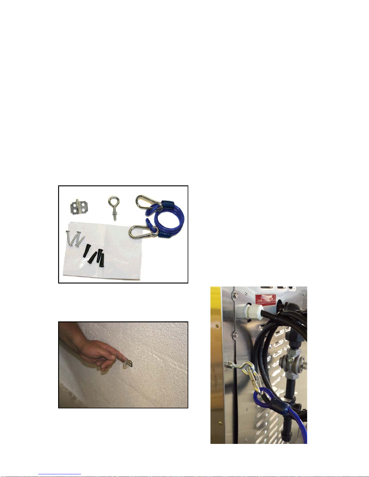
INSTALLATION INSTRUCTIONS FOR RESTRAINING DEVICE
1. Restraining device should be installed parallel (in line) with the power supply cord.
2. Restraining device parts list: See Figure A for a photo of the materials contained in the restraining kit.
3. Attach staple bracket: Fasten the staple bracket (Figure B) to a stud located in the wall that the power
receptacle is located on. Use the (4) #10 x 1” screws and plastic anchors if needed.
4. Install eyebolt: Thread jam nut onto eyebolt. Screw eyebolt into threaded hole below the power cord
connection point on back of smoker. Tighten eyebolt and then tighten jam nut to keep eyebolt tight
(Figure C).
5. Connect restraining cable: Attach one end of cable using the spring loaded hook to the eyebolt. Attach
other end of cable to the staple bracket using the other spring loaded hook.
6. Note: To provide strain relief the restraining cable must be shorter than the power supply cord and gas
line. The restraining device should always be connected when the smoker is in use.
Figure A
1. Staple bracket
2. Eyebolt with jam nut
3. Restraining cable
4. Spring loaded hook
5. #10 x 1” screws
6. Plastic anchors
7. Instruction sheet
Figure B
Figure C
1 2
3
4
5
6
7
16 of 38 Copyright 2015 by Southern Pride Distributing, LLC Volume 1
BURNER SPECIFICATIONS
Burner Models: Wayne P265-EP
Fuels: Natural or L.P. Gases
Electrical: 120 V.A.C., 60 Hz, 1 ph
NOTE: Orifice and valve setting must correlate with type of gas being supplied.
Gas valve: Control knob must be ON.
Firing Capacity
Firing Rate Btu 65,000
SRG-400 X
Main Orifice Size Chart
65,000 Btu/hr Natural Gas #26 (.147")
65,000 Btu/hr LP Gas #43 (.089")
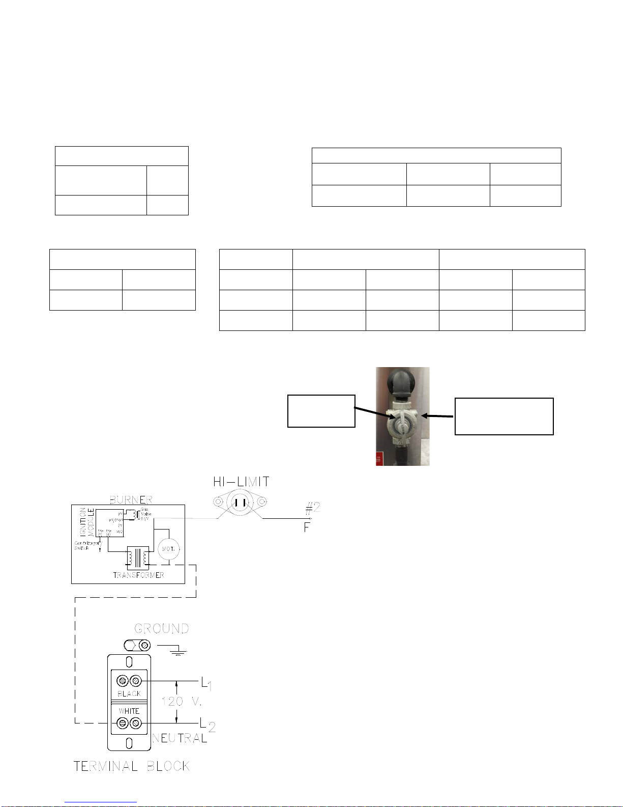
Wiring Diagram for Gas Burner
Gas Supply Line Pressure
Minimum Maximum Minimum Maximum
Natural 4.5” w.c. 10.0” w.c. 3.0” w.c. 3.5” w.c.
LP 11.0” w.c. 13.0” w.c. 9.5” w.c. 10.0” w.c.
Manifold Pressure
Gas valve-
On position Supply gas pressure
test port
Natural BCR-24
LP BCR-18
Pilot Orifice Size Chart

17 of 38 Copyright 2015 by Southern Pride Distributing, LLC Volume 1
VENTING INSTRUCTIONS
THE METHOD OF VENTILATION MUST BE APPROVED BY THE LOCAL CODE ENFORCE-
MENT AGENCY PRIOR TO EQUIPMENT INSTALLATION.
1. The smoker ventilation system should comply with this manual and the current edition of NFPA® 96.
2. It is recommended that Local Code Officials and a Commercial Kitchen Ventilation Contractor be consult-
ed prior to installation.
3. Provisions must be made for adequate air supply for the smoker. If the smoker is to be installed in a sealed
room or building utilizing exhaust fans, the room must be supplied with a return air system. Return air
must be equal or in excess of the exhausted air.
4. The smoker should be positioned to provide a direct, or shortest, path to the outside for the exhaust duct.
TYPE-1 CANOPY HOOD VENT
All smoker models may be installed under an approved Type-1 canopy hood system rated for commercial
cooking appliances.
Placement under a common hood shared with other appliances may be prohibited.
NFPA® 96 specifies a minimum canopy overhang of 6 inches on all sides. Southern Pride recommends a
minimum 18 inch overhang on the product loading door side of the smoker.
Exhaust fan size must be determined by a ventilation contractor specifically for your application. Hood
dimensions, exhaust duct length and routing all factor into the calculation.
Minimum Clearance Requirement from Combustible Material
Back…...18” (457mm) Firebox Door Side……...24” (610mm)
Top…….18” (457mm) Service Bay Side……….18” (457mm)
Front…...48” (1219mm)
NOTE: If provision is made for service access, Service Bay Side & Back
clearance can be reduced to 2” (51mm).
Canopy Hood

18 of 38 Copyright 2015 by Southern Pride Distributing, LLC Volume 1
OPERATION
The smoker should be operated in the following order (with all operations according to the subsequent instruc-
tions):
1. Load the product into the smoker and close the product loading doors.
2. Place the desired wood into the firebox and close the firebox door.
3. Ensure that the drain pan is empty and installed in the pan rails located under the smoker drain hole.
4. Set the control and start the cook cycle.
5. Once the cook cycle is complete, turn the control off.
6. Remove the product from the smoker.
7. Remove the ashes from the firebox.
8. Empty the grease from the grease pan.
PRODUCT LOADING INSTRUCTIONS
The smoker is equipped with seven (7), 18” x 26” product racks in its standard configuration for the loading of
product. The modular designed rack slide system has 1.5” spacing that allows the smoker to hold up to 27
product racks at one time.
1. Remove the wire product rack from the smoker.
2. Place the product directly on the product rack, leaving an air gap between each piece of product.
3. With the product placed on the rood rack, carefully slide the loaded product rack into the smoker starting
from the bottom rack slide position.
4. Repeat steps 2 and 3 until all product is loaded into the smoker. Product height will determine how many
rack slide spaces you need to advance to maintain an air gap between each loaded product rack.

19 of 38 Copyright 2015 by Southern Pride Distributing, LLC Volume 1
FIREBOX LOADING INSTRUCTIONS
1. The solid fuel should be handled in accordance with NFPA® 96.
2. Ensure the control is OFF, or in the Idle or Pause position, before opening the firebox door.
3. Use 1-3 logs, 3-5 inches in diameter, 10-12 inches long. Use green or slightly seasoned hardwoods, fruit-
woods, or charcoal (not to exceed six pounds). THE WOOD OR CHARCOAL IS ONLY USED TO
FLAVOR THE PRODUCT, NOT TO HEAT THE SMOKER.
4. Be sure to keep the wood 4” from the burner or ashes can accumulate on the burner and cause it to not
work properly.
5. Place the logs on top and inline with each other to minimize air flow around each log. This will help pro-
mote a smoldering, slow burn, which maximizes smoke.
6. The wood does not have to be lit manually; the smoker is equipped with a gas burner that will light the
wood. Combustible or flammable liquids shall not be used to assist ignition.
7. Tightly close the firebox door to prevent air from being pulled into the firebox.
8. If the cook menu was paused, a press of the start button is required to resume the menu..
CAUTION:
Remove coals and ashes from previous cook cycle before loading new wood
into the firebox. Refer to Ash Removal Instructions on page 23.
Do not use dry wood or kindling.
Do not overload firebox. Too much wood or charcoal can cause overheating
of the smoker. Keep wood at least 4 inches from the burner.
Do not allow ashes in or near the burner opening.

20 of 38 Copyright 2015 by Southern Pride Distributing, LLC Volume 1
CONTROL OPERATING INSTRUCTIONS
DIGITAL ROAST & HOLD CONTROL- Manual Menu
1. The product loading doors must be closed.
2. The control should be in the “IDLE” mode. (The burner, and convection fan will be off). If the control is
“OFF” a press of any button will bring the control back to “IDLE.”
3. A menu consists of a cook temperature, cook time, and, when the cook time has elapsed, a choice to end
the menu (HOLD OFF) or go into hold mode (HOLD TEMP SETPOINT).
4. Press the manual menu button (tEnP 1 will appear in the LED display), then press the up/down buttons to
obtain the desired cook temperature.
5. Press the manual menu button (tinE1 will appear in the LED display), then press the up/down buttons to
obtain the desired cook time.
6. Press the manual menu button (HtEnp will appear in the LED display), press the up/down buttons to obtain
the desired hold temp, if a hold temp is not desired press the down button until “OFF” is displayed in the
LED.
7. Programming the menu is complete. To start the menu, press the start/stop button one time. The control
will begin the menu.
8. To cancel or stop the menu, press and hold the start/stop button until “IDLE” is displayed in the LED.
9. When the cook cycle is complete there are two possible actions that can be taken. One is if a hold tempera-
ture was programmed into the menu, the control will momentarily sound an audible alarm then, “HOLD”
and the length of time the control has been in the hold mode will alternately flash in the LED display. The
control will maintain the hold temperature until the start/stop button is depressed to “END” the menu, and
bring the control to the “IDLE” mode.
10. If the hold temperature was programmed to “OFF” and the cook time has elapsed, “END” will be dis-
played on the LED display, and an audible alarm will sound continuously until the start/stop button is de-
pressed, to “END” the menu, and bring the control to the “IDLE” mode.
11. After the control has been in the “IDLE” mode for five minutes it will go to “OFF”, a press of any button
will bring the control back to “IDLE”.
12. After each cook cycle the ashes should be removed from the firebox, the grease emptied from the drain
pan, and the cool down cycle should be ran. To start a cool down cycle; press the cook temp button and
then press the down button until “OFF” is displayed in the LED display. This turns off the gas burner.
Press the start/stop button to start the cool down cycle. Run the cool down cycle until the smoker tempera-
ture falls below 90°.
Other manuals for SRG-400
1
Table of contents
Other Southern Pride Grill manuals


Popular Grill manuals by other brands


CASO DESIGN
CASO DESIGN DG 2000 operating manual

Meco
Meco 9350 Series Owner's/operator's manual

Mondial Designs Limited
Mondial Designs Limited SG-01 Instruction and Technical Service Manual

Montana
Montana KS12107 Assembly instructions

RUSTA
RUSTA MEMPHIS SUPREME manual

Fagor
Fagor MG-350 Instructions for use

Brinkmann
Brinkmann 810-9422-S owner's manual

Napoleon
Napoleon PRESTIGE II 450 Installation and operating instructions

GE
GE 106604 owner's manual

Weber
Weber 210 CLASSIC Assembly guide

Falcon
Falcon Dominator Plus G3512 Installation and servicing instructions

Kampa
Kampa BRUCE Installation and operating manual