Southern States LCSS1-02 User manual

SOUTHERN STATES
OWNER’S MANUAL
Convertible Deep Well Jet Pump
Installation/Operation/Parts
Southern States Cooperative
P.O. Box 26234, Richmond, VA 23230
SS313 (Rev. 7/15/05)
2760 0197

Safety 2
READ AND FOLLOW
SAFETY INSTRUCTIONS!
This is the safety alert symbol. When you see this
symbol on your pump or in this manual, look for
one of the following signal words and be alert to the
potential for personal injury:
warns about hazards that will cause serious
personal injury, death or major property damage if
ignored.
warns about hazards that can cause serious
personal injury, death or major property damage if
ignored.
warns about hazards that will or can cause
minor personal injury or property damage if ignored.
The label NOTICE indicates special instructions which
are important but not related to hazards.
Carefully read and follow all safety instructions in this
manual and on pump.
Keep safety labels in good condition.
Replace missing or damaged safety labels.
ELECTRICAL SAFETY
Capacitor voltage may be hazardous. To dis-
charge motor capacitor, hold insulated handle screwdriver
BY THE HANDLE and short capacitor terminals together.
Do not touch metal screwdriver blade or capacitor termi-
nals. If in doubt, consult a qualified electrician.
GENERAL SAFETY
Do not touch an operating motor. Modern
motors are designed to operate at high temperatures. To
avoid burns when servicing pump, allow it to cool for 20
minutes after shut-down before handling.
Do not allow pump or any system component to freeze.
To do so will void warranty.
Pump water only with this pump.
Periodically inspect pump and system components.
Wear safety glasses at all times when working on pumps.
Keep work area clean, uncluttered and properly lighted;
store properly all unused tools and equipment.
Keep visitors at a safe distance from the work areas.
Pump body may explode if used as a
booster pump unless relief valve capable of passing full
pump flow at 75 psi is installed.
WARNING
Hazardous pressure!
Install pressure relief
valve in discharge pipe.
Release all pressure on
system before working on
any component.
WARNING
Hazardous voltage.
Can shock, burn, or
cause death.
Ground pump before
connecting to power
supply. Disconnect power
before working on pump,
motor or tank.
Wire motor for correct
voltage. See “Electrical”
section of this manual and
motor nameplate.
Ground motor before
connecting to power
supply.
Meet National Electri-
cal Code, Canadian
Electrical Code, and local
codes for all wiring.
Follow wiring instruc-
tions in this manual
when connecting motor to
power lines.

Table of Contents 3
Thank you for purchasing a top quality, factory tested pump.
Page
General Safety .....................................................................................................2
Warranty ..............................................................................................................3
Replacing An Existing Pump ................................................................................4
New Shallow Well Installation..........................................................................5,6
• Well Point (Driven Point)
• Cased Well, 2" or larger casing
• Installation for Surface Water
New Deep Well Installation.................................................................................7
• 4-inch or larger well casing (A “Double Pipe” Well)
• 2-inch well casing (A “Single Pipe” Well)
Discharge Pipe and Pressure Tank Connections ...................................................8
Electrical .........................................................................................................9,10
Preparing To Start The Pump – Deep Well..........................................................11
Preparing To Start The Pump – Shallow Well ....................................................12
Troubleshooting..................................................................................................13
Repair Parts .......................................................................................................14
LIMITED WARRANTY
Southern States warrants to the original consumer of the products listed below, that they will be free from defects in material
and workmanship for the Warranty Period from the date of installation as noted.
Product Warranty Period
Jet pumps 1 year
4” Submersibles 5 years
Our warranty will not apply to any product that has been subject to negligence, misapplication, improper installation or main-
tenance. In the event a three phase submersible motor is operated with single phase power through a phase converter, or if
three-leg ambient compensated, extra-quick trip overload relays of recommended size are not used, our warranty is void.
Buyer’s only remedy and Southern States’s only duty is to repair or replace defective products (at Southern States’s choice).
Buyer agrees to pay all labor and shipping charges associated with this warranty and to request warranty service through the
installing dealer as soon as a problem is discovered. If warranty service is requested more than 30 days after the Warranty
Period has ended, it will not be honored.
SOUTHERN STATES SHALL NOT BE LIABLE FOR ANY CONSEQUENTIAL, INCIDENTAL, OR CONTINGENT DAMAGES
WHATSOEVER.
THE FOREGOING WARRANTIES ARE EXCLUSIVE AND IN LIEU OF ALL OTHER EXPRESS WARRANTIES. IMPLIED
WARRANTIES, INCLUDING BUT NOT LIMITED TO THE IMPLIED WARRANTIES OF MERCHANTABILITY AND FITNESS
FOR A PARTICULAR PURPOSE, SHALL NOT EXTEND BEYOND THE WARRANTY PERIOD PROVIDED HEREIN.
Certain states do not permit the exclusion or limitation of incidental or consequential damages or the placing of limitations on
the duration of an implied warranty, therefore, the limitations or exclusions herein may not apply. This warranty sets forth spe-
cific legal rights and obligations, however, additional rights may exist, which may vary from state to state.
Supersedes all previous publications
Southern States Cooperative, P.O. Box 26234, Richmond, VA 23230

Replacing an Existing Pump 4
DEEP WELL
Hazardous voltage. Disconnect power to pump before working
on pump or motor.
Step 1. Drain and remove the old pump. Check pipe for scale, lime, rust,
etc., and replace it if necessary.
Step 2. If your old pump has the suction pipe (the larger port – see Figure 1)
below the drive port, you will need to install flexible pipe between
the well head and the pump so that the connection will be correct.
(See Figure 2).
NOTICE: Your old ejector (in the well) may not be properly
matched to your new pump. If the pump does not perform properly,
we recommend that you install ejector kit FP4800.
Step 3. Install the pump in the system. Make sure that all pipe joints in the
suction pipe are air-tight as well as water tight. If the suction pipe
can suck air, the pump will not be able to pull water from the well.
Step 4. Adjust the pump mounting height so that the plumbing connections
do not put a strain on the pump body. Support the pipe so that the
pump body does not take the weight of piping or fittings.
You have just completed the well plumbing for your new deep well jet
pump. Please go to Page 8 for discharge pipe and tank connections.
SHALLOW WELL
Hazardous voltage. Disconnect power to pump before working
on pump or motor.
Step 1. Drain and remove the old pump. Check the old pipe for scale, lime,
rust, etc., and replace it if necessary.
Step 2. Install ejector kit FP4855 (kits are sold separately). Follow the
instructions provided with the kit. Be sure to align the venturi with
the top hole on the front of the pump (see Figure 3).
NOTICE: Always replace the ejector when replacing the pump in a
shallow well installation.
Step 3. Install the pump in the system. Make sure that all pipe joints in the
suction pipe are air-tight as well as water tight. If the suction pipe
can suck air, the pump will not be able to pull water from the well.
Step 4. Adjust the pump mounting height so that the plumbing connections
do not put a strain on the pump body. Support the pipe so that the
pump body does not take the weight of piping or fittings.
You have just completed the well plumbing for your new shallow well jet
pump. Please go to Page 8 for discharge pipe and tank connections.
Drive Pipe
sends water
down the well
to
drive
water
up through the
Suction Pipe
to the
Pump Suction
Suction
Port
S
uc
ti
on
(Larger)
Port
1604 0195
pi
ng om
itt
e
d
r
clarity
Discharge
Drive
(Smaller)
Port
Drive
Port
Suction
Pipe
Drive
Pipe
Well
Head
If well head and pump
don't match, braid
reinforced flexible pipe
to connect drive
and suction pipes.
1605 0195
20
40 60
80
100
2318 0296
Figure 1: Drive and Suction Functions
Figure 2: Reversed Connections to Well
Figure 3: Mount Ejector – Shallow Well

New Shallow Well Installation 5
WELL POINT INSTALLATION (Figure 4)
Step 1. Install ejector kit FP4855 (kits are sold separately). Follow the
instructions provided with the kit. Align the venturi with the top
hole on the front of the pump (see Figure 3).
Step 2. Drive the well, using “drive couplings” and a “drive cap”. “Drive
fittings” are threaded all the way through and allow the pipe ends
to butt against each other so that the driving force of the maul is
carried by the pipe and not by the threads. The ordinary fittings
found in hardware stores are not threaded all the way through the
fitting and can collapse under impact. “Drive fittings” are also
smoother than standard plumbing fittings, making ground penetra-
tion easier.
Step 3. Mount the pump as close to the well as possible.
Step 4. Use the fewest possible fittings (especially elbows) when connect-
ing the pipe from the well point to the pump suction port. The suc-
tion pipe should be at least as large as the suction port on the pump
(include a check valve – see Figure 4). Support the pipe so that
there are no dips or sags in the pipe, so it doesn’t strain the pump
body, and so that it slopes slightly upward from the well to the
pump (high spots can cause air pockets which can air lock the
pump). Seal the suction pipe joints with teflon tape or pipe joint
compound approved for use on PVC. Joints must be air- and water-
tight. If the suction pipe can suck air, the pump cannot pull water
from the well. If one well point does not supply enough water, con-
sider connecting two or three well points to one suction pipe.
You have just completed the suction piping for your new shallow well jet
pump. Please go to Page 8 for discharge pipe and tank connections
CASED WELL INSTALLATION, 2" OR LARGER
CASING (Figure 5)
Step 1. Install ejector kit FP4855 (kits are sold separately). Follow the
instructions provided with the kit. Align the venturi with the top
hole on the front of the pump (see Figure 3).
Step 2. Mount the pump as close to the well as possible.
Step 3. Assemble the foot valve, strainer, and well pipe (see Figure 5).
Make sure that the foot valve works freely.
Step 4. Lower the pipe into the well until the strainer is five feet above the
bottom of the well. It should also be at least 10 feet below the
well’s water level while the pump is running in order to prevent the
pump from sucking air. Install a sanitary well seal.
Step 5. Install a priming tee, priming plug, and suction pipe to the pump
(see Figure 5). Connect the pipe from the well to the pump suction
port, using the fewest possible fittings – especially elbows – as fit-
tings increase friction in the pipe. The suction pipe should be at
least as large as the suction port on the pump. Use teflon tape or a
teflon-based pipe joint compound on threaded pipe joints. Support
the pipe so that there are no dips or sags in the pipe, so it doesn’t
2319 0296
To Household
Water System
Suction Pipe
From Well
Pressure Gauge
Built-in
Check
Valve
Not
to
Scale
Relief
Valve
Priming Port
Control Valve
Drive
Point
20
4060
80
100
20
4060
80
100
Drive
Coupling
Check
Valve
Priming
Tee and
Plug
Figure 4: Driven Point Installation
Figure 5: Cased Well Installation
20
4060
80
100
2320 0296
To Household
Water System
Suction Pipe
From Well
Pressure Gauge
Not
to
Scale
Relief
Valve
Priming Port
Control Valve
Priming
Tee and
Plug
Well
Casing
Foot
Valve
Sanitary
Well Seal
Strainer
5-10'
At least
10'
Built-in
Check
Valve
20
4060
80
100

New Shallow Well Installation 6
strain the pump body, and so that it slopes slightly upward from the
well to the pump (high spots can cause air pockets which can air
lock the pump). Seal the suction pipe joints with teflon tape or a
teflon based pipe joint compound. Joints must be air- and water-
tight. If the suction pipe can suck air, the pump cannot pull water
from the well.
You have just completed the suction piping for your new shallow well jet
pump. Please go to Page 8 for discharge pipe and tank connections.
INSTALLATION FOR SURFACE WATER (Figure 7)
Step 1. Install ejector kit FP4855 (kits are sold separately). Follow the
instructions provided with the kit. Align the venturi with the top
hole on the front of the pump (see Figure 6).
Step 2. The pump should be installed as close to the water as possible,
with the fewest possible fittings (especially elbows) in the suction
pipe. The suction pipe should be at least as large as the suction port
on the pump.
Step 3. Assemble a foot valve and suction pipe (see Figure 7). Make sure
that the foot valve works freely. Use teflon tape or a teflon-based
pipe joint compound on threaded pipe joints. Protect the foot valve
assembly from fish, trash, etc, by installing a screen around it (see
Figure 9).
Step 4. Lower the pipe into the water until the strainer is five feet above the
bottom. It should also be at least 10 feet below the water level in
order to prevent the pump from sucking air.
Step 5. Install a priming tee, priming plug, and suction pipe to the pump
(see Figure 7). Support the pipe so that there are no dips or sags in
the pipe, so it doesn’t strain the pump body, and so that it slopes
slightly upward from the well to the pump (high spots can cause air
pockets which can air lock the pump). Seal the suction pipe joints
with teflon tape or a teflon based pipe joint compound. Joints must
be air- and water-tight. If the suction pipe can suck air, the pump
cannot pull water from the well.
You have just completed the plumbing for your new shallow well jet
pump. Please go to Page 8 for discharge pipe and tank connections.
20
40 60
80
100
2321 0296
Not
to
Scale Screen
At least
10'
5 to 10'
Foot
Valve
To Household
Water System
Suction Pipe
From Well
Pressure Gauge
Built-in
Check
Valve
Relief
Valve
Priming Port
Control Valve
20
40 60
80
100
20
40 60
80
100
Figure 6: Install Ejector
Figure 7: Surface Water Installation

New Deep Well Installation 7
4" OR LARGER WELL (Figure 8)
Step 1. Assemble ejector kit FP4800 (sold separately). See Figure 8. Follow
the instructions included with the kit in order to match the nozzle
and venturi to your well conditions.
Step 2. Mount the pump as close to the well as possible.
Step 3. Connect two pipes (1” drive, 1-1/4” suction) to the ejector and
lower the ejector into the well until it is five feet from the bottom. It
should also be at least 10 feet below the well’s water level while
the pump is running in order to prevent the pump from sucking air.
Step 4. Install a sanitary well seal and connect the ejector piping to the
pump. Use steel nipples through the well seal with flexible poly
pipe to avoid crushing the plastic pipe when tightening the seal.
Step 5. Support the pipe so that there are no dips or sags in the pipe, so it
doesn’t strain the pump body, and so that it slopes slightly upward
from the well to the pump (high spots can cause air pockets which
can air lock the pump). Seal the suction pipe joints with teflon tape
or a teflon based pipe joint compound. Joints must be air- and
water-tight. If the suction pipe can suck air, the pump cannot pull
water from the well.
You have just completed the plumbing for your new double pipe deep well
jet pump. Please go to Page 8 for discharge pipe and tank connections.
2" WELL (Figure 9)
Step 1. Mount the pump as close to the well as possible.
Step 2. Assemble ejector kit FP4840 (sold separately), well piping, and well
head adapter according to the instructions provided with the ejector
package. See Figure 9. Use galvanized drop pipe with turned cou-
plings to allow proper flow. Follow the instructions included with
the kit in order to match the nozzle and venturi to your well condi-
tions.
Step 3. Run two pipes (one smaller drive pipe, one larger suction pipe)
from the well to the pump. Support the pipe so that there are no
dips or sags in the pipe, so it doesn’t strain the pump body, and so
that it slopes slightly upward from the well to the pump (high spots
can cause air pockets which can air lock the pump). Seal the suc-
tion pipe joints with teflon tape or a teflon based pipe joint com-
pound. Joints must be air- and water-tight. If the suction pipe can
suck air, the pump cannot pull water from the well.
You have just completed the plumbing for your new single pipe deep well
jet pump. Please go to Page 8 for discharge pipe and tank connections.
20
4060
80
100
Not
to
Scale
Well
Head
Drive (Small)
Pipe to Well
Venturi
Nozzle
Ejector
Suction (Large)
Pipe from Well
20
40 60
80
100
To Household
Water System
Pressure Gauge
Relief
Valve Priming Port
Control Valve
Figure 8: 4” and Larger Deep Well
Figure 9: 2” (Single Pipe) Deep Well
20
4060
80
100
JET NO. J32P-24
20
4060
80
100
To Household
Water System
Not
to
Scale
Relief Valve
Priming Port
Control Valve
Drive (Small)
Pipe to Well
Well Casing
serves as
Drive Pipe
Suction Pipe
Venturi
Nozzle
Ejector
Pressure Gauge

Discharge Pipe and Pressure Tank Connections 8
PRE-CHARGE TANK CONNECTION (Figure 10)
Step 1. Install a close nipple and a tee in the pump discharge port (see
Figure 10). The pipe size must be at least as large as the discharge
port. Run a pipe or reinforced hose from one arm of the tee to the
port on the pre-charged tank.
Step 2. Install a second close nipple and tee with a relief valve in the tee.
Step 3. Connect the other end of the second discharge tee to your plumb-
ing system.
Step 4. Check the pre-charge of air in the tank with an ordinary tire gauge.
The pre-charge should be 2 PSI less than the cut-in setting of the
pump’s pressure switch. The pre-charge is measured
when there is
no water pressure in the tank.
Your new pump has a 30/50 PSI
switch, so adjust the tank pre-charge pressure to 28 PSI.
You have just completed the tank connection for your jet pump. Please go
to Pages 9 and 10 for electrical hookup.
STANDARD TANK CONNECTION (Figure 11)
Step 1. Install a close nipple and a tee in the pump discharge port. Mount a
relief valve in one arm of the tee.
Step 2. Install a second close nipple and tee in the open arm of the first
tee. Put a priming plug in one arm of the second tee.
Step 3. Run a pipe from the open arm of the second tee to the inlet port of
your tank. The pipe size must be at least as large as the pump
discharge port.
Step 4. Remove the 1/8" NPT pipe plug from the pump Air Volume Control
(AVC) port (see Figure 11). Run tubing from the pump’s AVC port to
the port on the AVC mounted on the tank. See instructions provided
with tank and AVC for details.
You have just completed the tank connection for your jet pump. Please go
to Pages 9 and 10 for electrical hookup.
20
4060
80
100
From
Well
20
4060
80
100
To Household
Water System
Pressure Ga
u
Relief
Valve
Priming Port
Control Valve
20
4060
80
100
To Household
Water System
Air Volume
Control
Air Volume
Control Tube
Priming Tee
and Plug
2325 0296
AVC
Port
From
Well
Relief
Valve
Pressure
Switch
Figure 10: Pre-charged Tank
Connections
Figure 11: Standard Tank Connections Sealing Pipe Joints
Use only Teflon tape or Teflon based joint compounds for
making all threaded connections to the pump itself. Do not use
pipe joint compounds on plastic pumps: they can react with
the plastic in pump components. Make sure that all pipe joints
in the suction pipe are air tight as well as water tight.
If the
suction pipe can suck air, the pump will not be able to pull
water from the well.

Electrical 9
Disconnect power before working on pump, motor, pressure switch, or wiring.
Plug Type Voltage Selector
Voltage is factory set to 230 volts. To change to 115 volts:
1. Make sure power is off.
2. Pull the voltage change plug off of the tabs.
3. Move the voltage change plug to the 115 volt posi-
tion. The plug will now cover 2 metal tabs and the
arrow on the plug will line up with the 115V arrow on
the label (see Figure 13).
4. Attach the incoming power leads to the two outer
screws on the pressure switch as shown in Figure 12.
5. Attach the ground wire to one of the grounding
connections, shown in Figure 12.
6. If there are other wires, they should be capped.
7. Reinstall the Motor end cover.
Dial Type Voltage Selector
Voltage is factory set to 230 volts. To change to 115 volts:
1. Make sure power is off.
2. Turn the dial counter-clockwise until 115 shows in the
dial window as shown in Figure 15.
3. Attach the incoming power leads to the two outer
screws on the pressure switch as shown in Figure 14.
4. Attach the ground wire to the grounding connections
as shown in Figure 14.
5. If there are other wires, they should be capped.
6. Reinstall the Motor end cover.
Figure 12:Voltage set to 230 volts, Plug Type
Ground Wire Connection
Voltage Change Plug
Pressure Switch
Power Connections
Figure 13:Voltage set to 115 volts, Plug Type
Figure 14:Voltage set to 230 volts, Dial Type
Ground Wire Connection
Power Supply Connections
Voltage
Change
Dial
Pressure Switch
Figure 15:Voltage set to 115 volts, Dial Type
NOTE: 1/2 HP motors are wired for 115 volts only, and have no motor wiring to change.
Your motor terminal board (located under the motor end cover) should look like one of those below.
If the motor can operate at either 115 or 230 volts, it is set at the factory to 230 volts. Do not change
motor wiring if line voltage is 230 volts, or if you have a single voltage motor.
Never wire a 115 volt motor to a 230 volt line.
MOTOR SWITCH SETTINGS

Electrical 10
Hazardous voltage. Can shock, burn, or kill. Connect ground
wire before connecting power supply wires. Use the wire size (including
the ground wire) specified in the wiring chart. If possible, connect the
pump to a separate branch circuit with no other appliances on it.
Explosion hazard. Do not ground to a gas supply line.
WIRING CONNECTIONS
Fire hazard. Incorrect voltage can cause a fire or seriously
damage the motor and voids the warranty. The supply voltage must be
within ±10% of the motor nameplate voltage.
NOTICE: Dual-voltage motors are factory wired for 230 volts. If necessary,
reconnect the motor for 115 volts, as shown. Do not alter the wiring in sin-
gle voltage motors.
Install, ground, wire, and maintain your pump in compliance with the
United States National Electrical Code (NEC) or the Canadian Electrical
Code (CEC), as applicable, and with all local codes and ordinances that
apply. Consult your local building inspector for code information.
Connection Procedure:
Step 1. Connect the ground wire first as shown in Figure 12. The ground
wire must be a solid copper wire at least as large as the power sup-
ply wires.
Step 2. There must be a solid metal connection between the pressure
switch and the motor for motor grounding protection. If the pres-
sure switch is not connected to the motor, connect the green
ground screw in the switch to the green ground screw under the
motor end cover. Use a solid copper wire at least as large as the
power supply wires.
Step 3. Connect the ground wire to a grounded lead in a service panel, to a
metal underground water pipe, to a metal well casing at least ten
feet (3M) long, or to a ground electrode provided by the power
company or the hydro authority.
Step 4. Connect the power supply wires to the pressure switch as shown in
Figure 12.
You have just completed the wiring for your pump.
Please go to Page 11 or 12 for startup preparations.
Branch
Max. Fuse DISTANCE IN FEET FROM MOTOR TO SUPPLY
Motor Load Rating 0 - 50 51 - 100 101 - 200 201 - 300 301 - 400 401 - 500
Model HP Volts Amp Amp AWG WIRE SIZE (mm2)
LCSS1-02 1/2 115 8.8 15 14 (2) 14 (2) 12 (3) 10 (5.5) 8/ (8.4) 8 (8.4)
LDSS1-02 3/4 115/230 9.4/4.7 15/15 14/14 (2/2) 14/14 (2/2) 10/14 (5.5/2) 10/14 (5.5/2) 6/14 (14/2) 6/12 (14/3)
Wiring Chart – Recommended Wire and Fuse Sizes

Preparing to Start the Pump – Deep Well 11
Never run pump dry. Running pump without water may cause
pump to overheat, damaging seal and possibly causing burns to persons
handling pump. Fill pump with water before starting.
Never run pump against closed discharge. To do so can boil
water inside pump, causing hazardous pressure in unit, risk of explosion
and possibly scalding persons handling pump.
Step 1. Open the control valve as far as possible (see Figure 16). Then
remove the priming plug from the pump and fill the pump, fill all
piping between the pump and the well, and make sure that all
piping in the well is full. If you have also installed a priming tee in
the suction piping, remove the plug from the tee and fill the suction
piping.
Step 2. Replace all fill plugs and close the control valve completely
(Figure 17).
Step 3. Power on! Start the pump and watch the pressure gauge. The
pressure should build rapidly to 50 PSI as the pump primes.
Step 4. After 2 or 3 minutes, the gauge should show pressure. If not, stop
the pump, remove the fill plugs, reopen the control valve, and refill
the pump and piping. You may have to repeat this two or three
times in order to get all the trapped air out of the piping. Don’t for-
get to close the control valve each time before you start the pump.
Step 5. When pressure has built up and stabilized at about 50 PSI, slowly
open the control valve (see Figure 18) and let the pressure drop
until the pressure gauge needle starts to flutter. When the needle
flutters, close the valve just enough to stop the flutter (see Figure
15). Your pump is now operating at its most efficient point.
Step 6. After the pump has built up pressure in the system and shut off,
check the pressure switch operation by opening a faucet or two and
running enough water out to bleed off pressure until the pump
starts. The pump should start when pressure drops to 30 PSI and
stop when pressure reaches 50 PSI. Run the pump through one or
two complete cycles to verify correct operation. This will also help
clean the system of dirt and scale dislodged during installation.
Congratulations on a successful installation.
If you were unsuccessful, please refer to the Troubleshooting section
(Page 13) or call our customer service technical staff.
Open control valve as far as possible
and fill pump and piping through
priming port or priming tee.
20
40 60
80
100
Figure 17: Prime Pump
Figure 18: Set Control Valve
20
4060
80
100
20
40 60
80
100
20
4060
80
100
20
40 60
80
100
20
4060
80
100
20
40 60
80
100
C-Close Control Valve
until Pressure Stabilizes
B-Watch for Pressure
Gauge to Flutter
2330 0296
A-Open Control Valve
Figure 16: Fill Pump
20
4060
80
100
2329 0296
Replace all fill plugs and close
control valve completely.
20
40 60
80
100

Preparing to Start the Pump – Shallow Well 12
Never run pump dry. Running pump without water may cause
pump to overheat, damaging seal and possibly causing burns to persons
handling pump. Fill pump with water before starting.
Never run pump against closed discharge. To do so can boil
water inside pump, causing hazardous pressure in unit, risk of explosion
and possibly scalding persons handling pump.
Step 1. Open the control valve as far as possible (see Figure 19). Then
remove the priming plug from the pump and fill the pump, fill all
piping between the pump and the well, and make sure that all pip-
ing in the well is full. If you have also installed a priming tee in the
suction piping, remove the plug from the tee and fill the suction
piping.
Step 2. Replace all fill plugs. Leave the control valve open (in a shallow
well installation, the control valve always stays open).
Step 3. Power on! Start the pump. The pump should pump water in two or
three minutes.
Step 4. If you don’t have water after 2 or 3 minutes, stop the pump and
remove the fill plugs. Refill the pump and piping. You may have to
repeat this two or three times in order to get all the trapped air out of
the piping. The control valve remains open throughout this procedure.
Step 5. After the pump has built up pressure in the system and shut off,
check the pressure switch operation by opening a faucet or two and
running enough water out to bleed off pressure until the pump
starts. The pump should start when pressure drops to 30 PSI and
stop when pressure reaches 50 PSI. Run the pump through one or
two complete cycles to verify correct operation. This will also help
clean the system of dirt and scale dislodged during installation.
Congratulations on a successful installation.
If you were unsuccessful, please refer to the Troubleshooting section
(Page 13) or call our customer service technical staff.
20
4060
80
100
20
4060
80
100
2328 0296
O
pen contro
l
va
l
ve as
f
ar as poss
ibl
e
and fill pump and piping through
priming port or priming tee.
Figure 19: Open Control Valve

SYMPTOM POSSIBLE CAUSE(S) CORRECTIVE ACTION
Motor will not run Disconnect switch is off Be sure switch is on
Fuse is blown or circuit breaker tripped Replace fuse or reset circuit breaker
Starting switch is defective DISCONNECT POWER; Replace starting switch
Wires at motor are loose, Refer to instructions on wiring (Page 9). DISCONNECT POWER; check and
disconnected, or wired incorrectly tighten all wiring.
Capacitor voltage may be hazardous. To discharge
capacitor, hold insulated handle screwdriver BY THE HANDLE and
short capacitor terminals together. Do not touch metal screwdriver
blade or capacitor terminals. If in doubt, consult a qualified electrician.
Pressure switch contacts are dirty DISCONNECT POWER and file contacts with emery board or nail file.
Motor runs hot and Motor is wired incorrectly Refer to instructions on wiring
overload kicks off Voltage is too low Check with power company. Install heavier wiring if wire size is too small
(See Electrical / Wiring Chart).
Pump cycles too frequently See section below on too frequent cycling
Motor runs but no Pump in new installation did In new installation:
water is delivered* not pick up prime through:
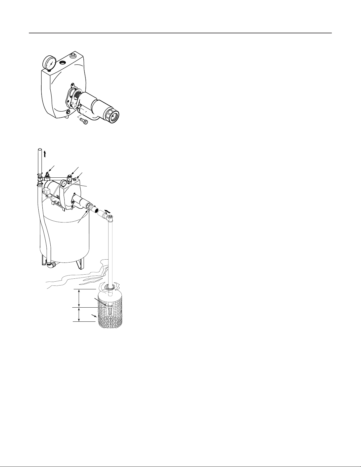
1. Improper priming 1. Re-prime according to instructions
2. Air leaks 2. Check all connections on suction line, AVC and ejector
3. Leaking foot valve or check valve 3. Replace foot valve or check valve
Pump has lost prime through: In installation already in use:
1. Air leaks 1. Check all connections on suction line and shaft seal
2. Water level below suction pipe inlet 2. Lower suction line into water and re-prime. If receding water level
in well exceeds suction lift, a deep well pump is needed.
Foot valve or strainer is plugged Clean foot valve or strainer
Ejector or impeller is plugged Clean ejector or impeller
Check valve or foot valve is stuck shut Replace check valve or foot valve
Pipes are frozen Thaw pipes. Bury pipes below frost line. Heat pit or pump house.
Foot valve and/or strainer are Raise foot valve and/or strainer above bottom of water source.
buried in sand or mud Clean foot valve and strainer.
Water level is too low for shallow well A deep well jet package may be needed (over 25 ft. to water) to deliver
setup to deliver water water to full capacity
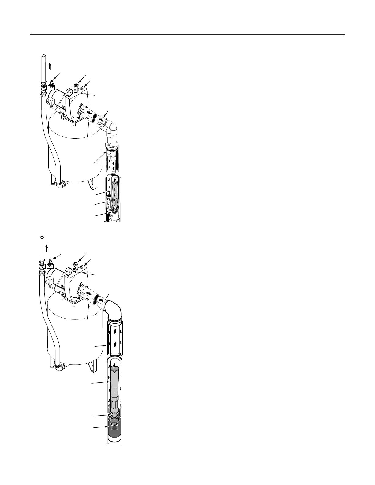
Pump does not Water level in deep well is lower than Replace nozzle and venturi with correct combination for the well; lower
deliver water to full estimated the ejector to correct level in the well
capacity Steel piping (if used) is corroded or Replace with plastic pipe where possible, otherwise with new steel pipe
limed, causing excess friction
Piping is too small in size Use larger piping
Pump delivers water but
Pressure switch is out of adjustment or DISCONNECT POWER; adjust or replace pressure switch
does not shut off or contacts are welded together
pump cycles too Faucets have been left open Close faucets
frequently Venturi, nozzle or impeller is clogged Clean venturi, nozzle or impeller
Water level in deep well is lower than
estimated Replace nozzle and venturi with correct combination for the well
Standard pressure tank is waterlogged Drain tank to air volume control port. Check AVC for defects. Check for
and has no air cushion air leaks at any connection.
Pipes leak Check connections
Foot valves leak Replace foot valve
Air charge too low in pre-charged tank DISCONNECT POWER and open faucets until all pressure is relieved
Using tire pressure gauge, check air pressure in tank at valve stem
located on the tank. If less than pressure switch cut-in setting (30-50
PSI), pump air into tank from outside source until air pressure is 2 PSI
less than cut-in setting of switch. Check air valve for leaks (use soapy
solution) and replace core if necessary.
Air spurts from faucets Pump is picking up prime When pump picks up prime, all air will be ejected
Leak in suction side of pump Suction pipe is sucking air. Check joints for leaks.
Well is gaseous Consult factory about installing a sleeve in the well
Intermittent over-pumping of well. Lower foot valve if possible, otherwise restrict pump discharge
(Water drawn down below foot valve.)
Troubleshooting 13
* (Note:
Stop pump;
then check prime
before looking for
other causes.
Unscrew
priming
plug and see if water
is in priming hole).

Repair Parts 14
2
3
1
4
5
6
7
8
9
10 1112
13
14
15
16
17
1819
20
Model and HP
Key Part LCSSI-02 LDSSI-02
No. Description Qty. 1/2HP 3/4HP
1 Motor - 60 Cycle 1 AS100CL A100DLL
2 Slinger 1 17351-0009 17351-0009
3 Seal Plate 1 N3-9 N3-9
4 Seal Plate Gasket 1 N20-35 N20-35
5 Shaft Seal 1 U109-6A U109-6A
6 Impeller 1 J105-40P J105-42P
7 Diffuser 1 L1-25P L1-25P
8 Diffuser Gasket 1 L21-I L21-I
9 Switch Tube 1 U37-672P U37-672P
10 Pressure Gage 1 U239-3 U239-3
11 3/4" NPT Priming Plug 1 U78-60CT U78-60CT
12 Control Valve Assembly 1 01322 01322
13 Pump Body Assembly 1 L76-44 L76-44
14 1/4" NPT Drain Plug 1 * *
15 1/8" NPT Pipe Plug 1 * *
16 1/4 NPT Hose Barb, Straight 1 U111-211T U111-211T
17 3/8 - 16 x 1-1/4" Capscrews 4 * *
18 Pressure Switch 1 U217-1202 U217-1202
19 1/2" Locknut 1 U36-112ZP U36-112ZP
20 Connector 1 L43-5C L43-5C
* Standard hardware item, purchase locally.

15

16
This manual suits for next models
1
Table of contents
Other Southern States Water Pump manuals
Popular Water Pump manuals by other brands

Silicon Solar
Silicon Solar AquaJet-Pro-PUMP1224 installation manual

Edwards
Edwards HV8000 VF instruction manual

Carver Pump
Carver Pump RSA Installation, operation and maintenance instructions

Enerpac
Enerpac CULP10 Operation and maintenance manual

dosatron
dosatron D40 owner's manual

ALFRA
ALFRA AHP-M1 user manual