Southland SELS60 User manual

WARNING: CONTAINS LEAD. May be harmful if eaten or chewed. May generate dust containing lead. Wash hands after use.
Keep out of reach of children.
WARNING: This product can expose you to chemicals including lead, which is known to the State of California to cause can-
cer and birth defects or other reproductive harm. For more information go to www.P65Warnings.ca.gov.
Look inside for:
Page
Safety Definitions ............................2
Important Safety Information ..................3-5
Product Specifications ........................6
Controls & Features ..........................6
Safety Decals ...............................7
Assembly ..................................8
Preparation for Operation......................8
Operation ..................................9
Maintenance..............................10-11
Transporting ............................... 11
Troubleshooting ............................ 12
Technical Service ........................... 12
Slope Guide ............................... 13
Warranty ................................. 14
07/12/2018 Printed in China A203548
Operator’s Manual
6 TON ELECTRIC
LOG SPLITTER
KEEP THIS MANUAL FOR FUTURE REFERENCE
If you need assistance or have any questions,
CALL TOLL FREE: 1-800-737-2112
Model No. SELS60
Record the following for future reference:
Mfg. date code: __________________
Date of purchase: ________ Attach a copy of your sales receipt.
Consumer toll free number: 1-800-737-2112
Refer to the website for electronic manual and parts book.
www.southlandpowerequipment.com
IMPORTANT:
Thank you for purchasing this Southland® Log Splitter. This manual provides complete instructions for
safely operating and maintaining your Log Splitter. Read and save these instructions. Refer to this manual each time before
using your Log Splitter.

Questions? Call Toll Free at 1-800-737-2112 Copyright © 2018 MAT Engine Technologies, LLC
EN - 2 EN - 3
Safety Alert Symbols:
Safety Warning Symbols:
Safety Definitions
• Save all instructions
The symbols below identify important safety information in this manual. Become familiar with these symbols
and the warnings associated with them.
Personal Safety Symbols:
Indicates an imminently hazardous situation which, if not avoided, will result in death or
serious injury.
Indicates a potentially hazardous situation which, if not avoided, could result in death or
serious injury.
Indicates a potentially hazardous situation which, if not avoided, may result in minor or
moderate injury.
Indicates a practice not related to personal injury which, if not avoided, may result in
property damage.
CAUTION
NOTICE
DANGER
The following symbols can be found on your Log Splitter. Carefully read and understand their meaning.
Wear heavy-duty protective gloves when operating this product.
Wear eye and ear protection complying with ANSI Z87.1.
Wear protective footwear when operating this product.
Look for this symbol to point out important safety precautions. It means: Attention! Become
Alert! Your Safety Is Involved.
Read, understand and follow operator’s manual before operating this machine. Failure to
follow directions could result in serious injury.
Electric shock hazard! Disconnect electrical power before making adjustments, or performing
maintenance on Log Splitter.
Electric shock hazard! Do not use in wet or rainy conditions. Use only approved outdoor
extension cords with a grounding pin.
Keep bystanders, pets and children at least 10 feet away from the machine while it is in
operation. Stop machine if anyone enters the area.
Avoid hand injury! Keep hands away from wedge, ram and other moving parts.
Check for hydraulic fluid leaks by passing a piece of paper or cardboard underneath or over the
area of the leak. Do not check for leaks with your hand. Fluid escaping from the smallest hole,
under pressure, can have enough force to penetrate the skin resulting in tissue damage and
cause serious injury or death.
Do not operate or transport the Log Splitter on slopes greater than 5 degrees. Block wheels to
prevent movement.
Hydraulic cylinder and other components can become very hot. Avoid contact. Wear gloves
when operating Log Splitter.
WARNING

Questions? Call Toll Free at 1-800-737-2112 Copyright © 2018 MAT Engine Technologies, LLC
EN - 2 EN - 3
Responsibility of Operator:
Training Safety:
Preparation Safety:
1. Carefully read and follow these safety instructions. Failure to do so can result in serious injury.
2.
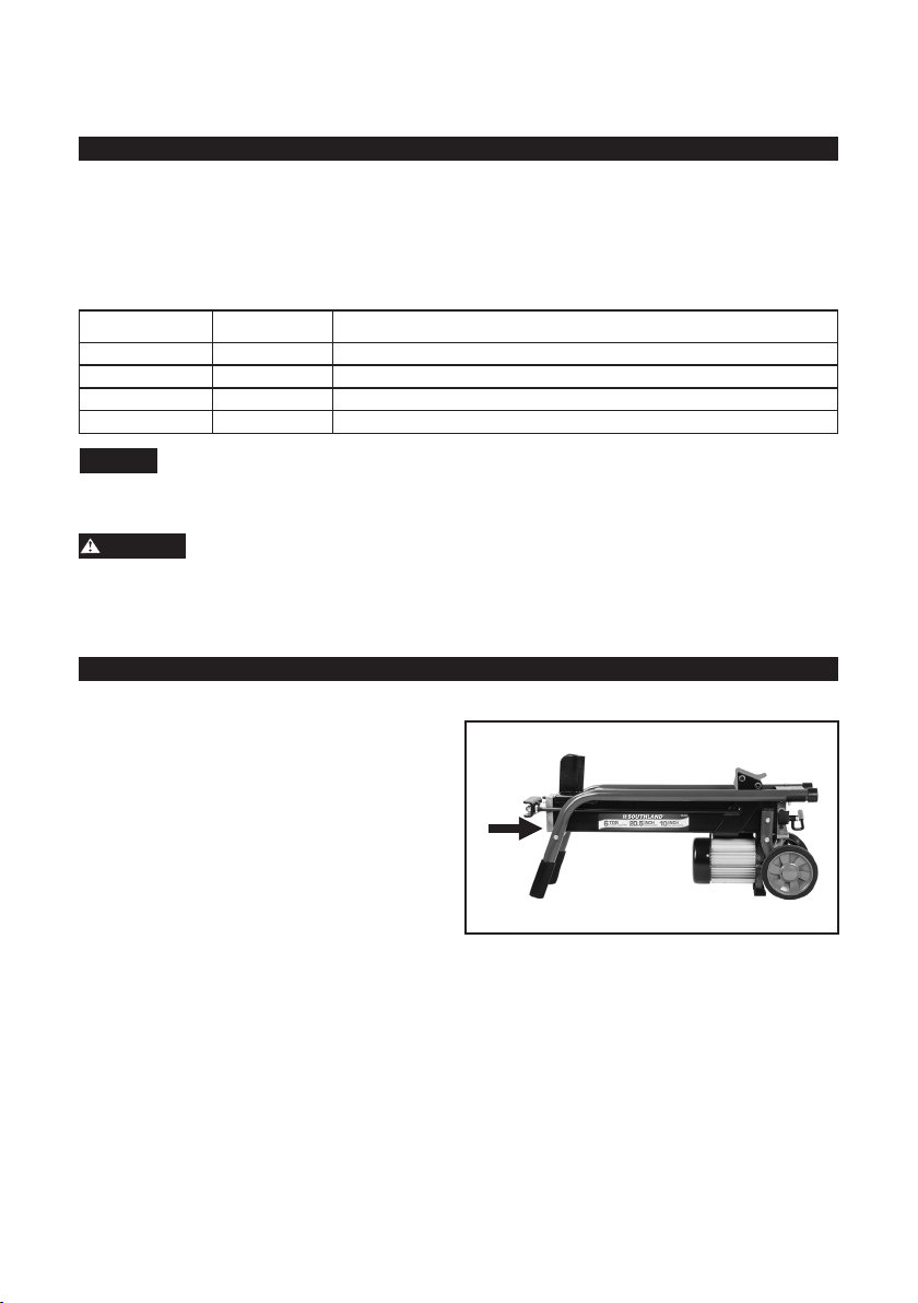
Know your product. Read and understand this manual before use. Compare the illustrations to machine.
Learn location and function of all controls. Thoroughly understanding the unit before use will result in the
best performance and safety.
3. Follow all instructions when assembling the unit. If the unit was purchased in assembled condition, the
operator must check the machine carefully to make sure it was assembled according the instructions in the
manual before use.
4. Regularly inspect the Log Splitter. Make sure parts are not bent, damaged, or loose.
5. Use this equipment for its intended purpose only. The intended purpose is to split wood for use in replaces.
6. Operate the machine only with guards, shields, and other safety items in place and working correctly.
7. Service the machine only with authorized or approved replacement parts.
8. Complete all unit maintenance and adjustments according to the instructions in this manual.
- Look for this symbol on your Log Splitter to point out important safety precautions.
It means: “ Attention! Become Alert! Your Safety Is Involved.”
Do not use Log Splitter in wet or in rainy conditions due to risk of electrical hazard. Electrical shock may result.
The Log Splitter is capable of amputating or crushing hands and ngers. Read and follow all warnings and
safety instructions on the Log Splitter and in this manual. Failure to do so can result in serious injury or death to
you or bystanders.
In order to avoid electrical or crushing hazard when setting up, transporting, adjusting or making repairs,
always disconnect plug from electrical source.
1. Read, understand and follow the operating and service instruction manual carefully. Be thoroughly familiar
with the controls and the proper use of the equipment. Know how to stop the machine and disengage the
controls quickly.
2. Never allow children to operate the equipment. Never allow adults to operate the equipment without
proper instruction.
3. Keep bystanders, pets and children at least 10 feet (3 m) from the machine while it is in operation. Stop
the machine if anyone enters the area.
4. Keep in mind that the operator or user is responsible for accidents or hazards occurring to other people,
their property and themselves.
1. Thoroughly inspect the area where the Log Splitter is to be used and remove all foreign objects.
2. Operate only on level ground to ensure machine stability. Do not operate or transport Log Splitter on
slopes greater than 5 degrees. It is recommended that the Log Splitter be placed on a stable, flat and level
work platform approximately 24-30 inches high. Always use two adults to lift the unit.
3. Do not operate the equipment without wearing adequate outer garments and safety goggles. Avoid
loose-fitting clothes or jewelry and use protective footwear that will improve footing on slippery surfaces.
Wear leather work gloves. Wear protective hair covering to contain long hair, preventing it from getting
caught in the Log Splitter.
4. During operation, foreign objects can be ejected and can result is severe eye damage. Always wear safety
glasses with side shields or safety goggles during operation and while performing an adjustment or repair.
Always use eye protection which is marked to comply with ANSI Z87.1.
5. Never use in an explosive atmosphere. Normal sparking of the motor could ignite fumes or flammable dust.
6. Never attempt to make any adjustments while the motor is connected to an electrical source.
Important Safety Information
• Save all instructions
WARNING
WARNING
WARNING

Questions? Call Toll Free at 1-800-737-2112 Copyright © 2018 MAT Engine Technologies, LLC
EN - 4 EN - 5
Hydraulic Safety:
Electrical Safety:
Electrical Connection:
Important Safety Information (Continued)
• Save all instructions
1. The hydraulic system of the Log Splitter requires careful inspection. Wear eye protection and gloves prior
to inspection.
2. Hydraulic uid may be under high pressure or may be hot and can cause personal injury.
3. Escaping hydraulic uid can create a re hazard and ignite if exposed to an ignition source.
4. Check for hydraulic uid leaks by passing a piece of paper or cardboard underneath or over the area of
the leak.
5. Do NOT check for leaks with your hand.
6. Fluid escaping from the smallest hole, under pressure, can have enough force to penetrate the skin resulting
in tissue damage and cause serious injury or death. Machine operation should stop until any detected leak
is repaired.
7. Seek professional medical attention IMMEDIATELY if injured by escaping hydraulic uid. Serious infection or
reaction can develop if medical treatment is not administered immediately.
8. Do NOT adjust the hydraulic valve. The pressure relief valve on the Log Splitter is preset at the factory. Only
a qualied service technician should perform this adjust.
Use only 3-wire extension cords that have 3-prong grounding plugs and 3-pole receptacles that accept the Log
Splitter’s plug. When using the Log Splitter at a considerable distance from the power source, use an extension
cord heavy enough to carry the electrical current that the Log Splitter will draw. An undersized extension
cord will cause a drop in line voltage, resulting in a loss of power and causing the motor to overheat. Use the
information provided below to determine the minimum wire size required in an extension cord. Only round
jacketed cords listed by Underwriter’s Laboratories (UL) should be used. Only use extension cords of 50 feet
or less.
When working with the tool outdoors, use an extension cord that is designed for outside use. This is indicated
by the letters WA (weather approved) on the cord’s jacket. Before using an extension cord, inspect it for loose
or exposed wires and cut or worn insulation.
Keep the extension cord clear of the working area. Position the cord so that it will not get caught on lumber, Log
Splitter or other obstructions. Failure to do so can result in serious personal injury.
Check extension cords before each use. If damaged, replace immediately. Never use the Log Splitter with a damaged
cord. Touching the damaged area could cause electrical shock resulting in serious injury.
This Log Splitter is powered by a precision built electric motor. It should be connected to a power supply that is
120 volts, 60 hz, AC only (normal household current). Do not operate this tool on direct current (DC). The power
supply circuit must be a 12 gauge wire - 20 amp circuit.
WARNING
WARNING
WARNING
Hydraulic fluid may be under high pressure or may be hot and can cause personal injury. Read, understand and
follow the following safety precautions.
Cord Length In Feet Minimum Wire Size (A.W.G.)*
25’..............................................................................................................................................................14 gauge
50’..............................................................................................................................................................12 gauge
*A.W.G. = American Wire Gauge

Questions? Call Toll Free at 1-800-737-2112 Copyright © 2018 MAT Engine Technologies, LLC
EN - 4 EN - 5
Grounding Instructions:
Operation:
Important Safety Information (Continued)
• Save all instructions
This tool is equipped with an electric cord having an equipment-grounding conductor and a grounding plug. The plug
must be plugged into a matching outlet that is properly installed and grounded in accordance with all local codes and
ordinances. Do not modify the plug provided. If it will not t the outlet, have the proper outlet installed by a
qualied electrician. Improper connection of the equipment-grounding conductor can result in a risk of electric
shock. The conductor with insulation having an outer surface that is green with or without yellow stripes is the
equipment-grounding conductor. If repair or replacement of the electric cord or plug is necessary, do not
connect the equipment-grounding conductor to a live terminal. Check with a qualied electrician or service
personnel if the grounding instructions are not completely understood, or if in doubt as to whether the tool is
properly grounded. Repair or replace a damaged or worn cord immediately.
1. Do NOT put hands near moving parts. Contact with the splitting wedge can amputate ngers and hands.
2. Never allow bystanders within 10 feet of the machine while running. Keep children and pets away.
3. Never operate the machine without proper guards, plates or other safety protective devices in place.
4. Keep your hand away from splits that occur during the splitting operation. These may close suddenly and
crush or amputate fingers and hands. Do not remove jammed logs with your hands.
5. Exercise caution to avoid slipping or falling. Maintain a work space clean of wood and debris.
6. Stop motor and disconnect from electric power source when leaving the operating position, and when
making any repairs, adjustments and inspections.
7. Take all possible precautions as recommended by the manufacturer when leaving the machine unattended.
Stop the engine, do not leave the unit unattended until all moving parts have come to a complete stop.
8. Do not overload the machine by attempting to split any material beyond manufacturer’s recommendation.
9. Use only attachments and accessories approved by the manufacturer of the machine.
10. Never operate the machine without good visibility or light. Do not operate at night.
11. Do not operate the machine while under the influence of alcohol or any drugs that can affect your ability to
safely operate the splitter.

Questions? Call Toll Free at 1-800-737-2112 Copyright © 2018 MAT Engine Technologies, LLC
EN - 6 EN - 7
Specifications
• Save all instructions
Controls & Features
Unit Weight............................................105 lbs (48 kg)
Ram Force........................................................... 6 Ton
Cycle Time................................................. 18 Seconds
Wedge Size .............................. 5 Inch Hardened Steel
Gear Pump................................................ Singe Stage
Max Log Length......................................... 20.5 Inches
Max Log Diameter....................................... 10 Inches*
Electrical Requirement ....................... 120V AC - 60Hz
Hydraulic Oil Type ......... Shell Tellus 22, Mobil DTE10,
ARAL Vitam GF 22, BP Energol HLP-HM22
Hydraulic Fluid Max............... Approximately 3.5 Liters
Max Hydraulic Pressure ................................ 3480 PSI
Ambient Operating Temperatures ...............14° - 100°F
(-10° to 38°C)
Read, understand and follow this owner’s manual
before operating the equipment. Familiarize yourself
with the location and function of the controls and
features. (Fig 1)
1. Motor Switch - Depress switch to electrically
activate the electric motor. Upon release, the
switch will return to an off position.
2. Hydraulic Control Lever - Controls the forward
and backward movement of ram.
3. 5 Inch Wedge - Splits and separates the log.
4. Ram - Pushes the log into the wedge.
5. Vent Screw - Loosen to prevent buildup of
internal air pressure. Tighten after use and
when moving to prevent leakage.
6. Hydraulic Pump - Pumps the hydraulic oil
through the system.
7. Support Leg - Supports the Log Splitter
while operating.
8. Handles - For moving the Log Splitter.
9. Oil Drain and Fill Port - For adding or removing
hydraulic fluid.
10. Reset Button - Detects overload and disables
motor. Push to reset.
11. Stroke Limiter - Reduces the return stroke for use
with shorter logs.
12. Pressure Limiting Screw - Factory set. Do NOT
adjust.
* Maximum Log Diameter is an approximate. Actual maximum log diameter is dependent upon log shape,
consistency, wood type and internal moisture.
4
2
311
76
5
9
1
Fig 1
8
10
12

Questions? Call Toll Free at 1-800-737-2112 Copyright © 2018 MAT Engine Technologies, LLC
EN - 6 EN - 7
This Log Splitter has been designed and manufactured to provide you with the safety and reliability you would
expect from an industry leader in outdoor power equipment manufacturing.
Although reading this manual and the safety instructions it contains will provide you with the necessary basic
knowledge to operate this equipment safely and effectively, we have placed several safety labels on the
Log Splitter. This is to help remind you of the important information and warn you of specific hazards while
operating the machine.
These important safety labels are illustrated below, and are shown here to help familiarize you with the
location and content to the safety messages you will see as you perform normal splitting operations.
Please review these labels now. If you have any questions regarding their meaning or how to comply with
these instructions, reread the “Important Safety Information” sections or contact your local dealer.
Should any of the safety labels become unreadable because of being worn, faded or otherwise damaged
during the use of your Log Splitter, please contact your local authorized dealer to order replacement label. The
safety labels are easily applied, and will act as a constant visual reminder to you and others who may use the
equipment. Following the safety instructions is necessary for safe, effective operation of your Log Splitter.
Safety Decals
• Save all instructions If you need assistance or have any questions,
CALL TOLL FREE: 1-800–737-2112
NOTICE
- Before use, loosen vent screw three turns.
- After use and before moving, retighten vent screw
to avoid leakage.
READ AND FOLLOW
OPERATING INSTRUCTIONS
BEFORE USING LOG SPLITTER.
To Split Wood: Depress motor switch and move control lever downward. Release for return.
- Keep bystanders at least 10 feet
away.
IMPACT OR PINCH HAZARD
- Only one person should operate and
load the log splitter, staying within
the designated operating zone.
ELECTRIC
SHOCK
HAZARD
- Do not use in
wet or damp
conditions.
- Disconnect from
power before
servicing.
CRUSH HAZARD
To avoid injury:
Keep arms
and hands
away from
moving parts.

Questions? Call Toll Free at 1-800-737-2112 Copyright © 2018 MAT Engine Technologies, LLC
EN - 8 EN - 9
Unpacking Instructions:
Carton Contents:
Wheel Assembly:
Before Using the Log Splitter:
Checking Hydraulic Fluid Level:
Maximum Pressure Limiting Screw:
Assembly
• Save all instructions
Read, understand and follow all instructions for assembly and operation. Failure to properly assemble this
equipment could result in serious injury to the user or bystanders, or cause equipment damage.
Set the shipping crate on a solid, flat surface and carefully remove the lid. Use two adults and take all parts
out of the shipping crate and inspect the components to ensure there are no missing pieces before starting to
assemble the Log Splitter.
NOTE: Before operating the Log Splitter, the vent screw MUST ALWAYS BE LOOSENED THREE TURNS until air
can move in and out of the oil tank smoothly. Air flow through the vent screw hole should be detectable during
log splitter operations. Before moving the Log Splitter, make sure the vent screw is tightened to avoid oil leakage.
Failure to loosen the vent screw will keep the air inside the hydraulic reservoir sealed and it will be compressed.
This compressed air will damage the seals of the hydraulic system and may cause permanent damage to the
Log Splitter.
Assure the power cord is routed away from all moving parts and sharp edges and is not under the support legs
of the Log Splitter.
Do NOT adjust the maximum pressure limiting screw. The maximum pressure was set at the factory by
qualified mechanics using professional instruments. Unauthorized resetting may result in serious injury or
damage to the Log Splitter.
1. Make sure the Log Splitter is unplugged.
2. Using the handle, stand the Log Splitter on
the end near the wheels.
3. Unscrew oil drain bolt with dipstick to
remove it, wipe clean and reinsert the bolt
with dipstick.
4. Remove the dipstick and check to see if the
oil is between the two grooves.
5. If additional fluid is required, fill with fresh
hydraulic oil until the level is between the
two grooves of the dipstick.
6. Replace and tighten the dipstick bolt.
• Frame assembly
• (2) Wheel assemblies
• Hardware pack
• Owner’s manual
• (2) Hub caps
1. Insert wheel pin through wheel, washer, tube
bushing and secure with hairpin cotter.
Repeat for second wheel. (Fig 2-3)
2. Insert hub cap by pressing into wheel until it
is secured.
Preparation for Operation
• Save all instructions
CAUTION
NOTICE
NOTICE
NOTICE
Fig 2 Fig 3
The Log Splitter is filled with hydraulic fluid at the factory, but check the level prior to each use.

Questions? Call Toll Free at 1-800-737-2112 Copyright © 2018 MAT Engine Technologies, LLC
EN - 8 EN - 9
Controlling the Log Splitter:
Splitting Wood:
Use of the Stroke Limiter:
Freeing a Jammed Log:
NOTE: The operator zone is when the operator is positioned at the rear of the Log Splitter near the control lever.
This Log Splitter is equipped with a control system that requires use of both hands of the operator. The left
hand controls the hydraulic control lever while the right hand controls the push button on/off switch. The Log
Splitter will not operate if either control is not simultaneously engaged. Only after the hydraulic control lever is
released will the log ram return backward to the starting position.
Place the log lengthwise on the Log Splitter and split in the direction of the grain. Using the right hand, push
down and hold the push button on/off switch. Using the left hand, push down and hold the hydraulic control
lever. Once the wood is split, release both controls. The ram will auto return to the starting position. (Fig 4)
Impact Hazard! Log may suddenly split and eject. Stay clear of the projected wood.
If the Log Splitter stalls while trying to split a log, retract
the ram, rotate the log by 90oto see whether it can be
split in a different direction. If you are not able to split
the log, this means that its hardness or structure
exceeds the capacity of the machine and the log
should be discarded.
Always set the log rmly on the log retaining tubes and
log cradle. Make sure the log does not twist, rock or slip
while being split. Do not elevate the log on the wedge.
This may result in machine damage. (Fig 5)
Split the log in the direction of its grain. Do not place log across the Log Splitter for splitting. It may be
dangerous and may seriously damage the machine. Do not attempt to split 2 pieces of logs at the same time.
If the wood to be split is consistently shorter than 20.5 inches in length, you can use the stroke limiter to
control the starting distance between the ram and the wedge.
To adjust: With the ram fully extended, release the motor switch while continuing to hold down the hydraulic
control lever. Have a second person loosen the adjustable knob and slide the stroke limiter to the desired
postion. With the knob oriented so it faces away from the unit, tighten the knob. Release the hydraulic control
lever only after the second person has secured the knob and moved away from the Log Splitter. The ram will
now stop at a position which requires less travel until it engages the log.
Pinch Hazard! Keep hands and finger clear of all moving parts.
At the end of the stroke or if the units stalls, do not continue to engage both controls simultaneously for more
than 5 seconds. After this time interval, the oil will overheat and the machine could be damaged.
Operation
• Save all instructions
NOTICE
WARNING
WARNING
CAUTION
1. Release both controls.
2. After the ram completely retracts, insert a wood wedge
under the jammed log. (Fig 6)
3. Using the ram, slowly push the wood wedge completely
under the jammed log.
4. Repeat above procedure with sharper slope wedge woods
until the log is completely freed.
The jammed log may suddenly disengage. Maintain a safe distance
away from the log during this operation.
Fig 5
Fig 6
Fig 4
Correct Incorrect
Wood Wedge

Questions? Call Toll Free at 1-800-737-2112 Copyright © 2018 MAT Engine Technologies, LLC
EN - 10 EN - 11
Replacing Hydraulic Oil:
Maintenance
• Save all instructions
1. Make sure the Log Splitter is unplugged.
2. Unscrew oil drain bolt with dipstick to remove it.
3. Turn the Log Splitter on the support leg side over a
container to drain the hydraulic oil.
4. Lift the Log Splitter by the motor end.
5. Rell with hydraulic oil with 3.7 liters (118 oz) and
use type dened in the specications table on
page 6.
6. Clean the surface of dipstick on the oil drain bolt and put it back into the oil tank while keeping the Log Splitter
vertically.
7. Make sure the level of the relled oil is just between the two grooves around the dipstick.
8. Clean the oil drain bolt before replacing it. Make sure they are tightened to avoid leakage before placing the
Log Splitter horizontally.
NOTE: Periodically check the oil level and ll as necessary to ensure it is between the two grooves around
the dipstick.
NOTE: See recommended hydraulic oil types on page 6 under “Specication” section.
Performing Maintenance:
• Before performing maintenance, the Log Splitter must be placed in maintenance mode. Disconnect from
electrical power source and move the control lever forward and backwards to relieve the hydraulic pressure
before performing any maintenance, make sure all guards, shields and safety features are put back in place
before operating the Log Splitter.
• Periodically check all fasteners for tightness and leaks.
• Annually clean and lightly lubricate all moving parts or when needed.
• Use a glossy enamel spray paint to touch up scratched or worn painted metal surfaces.
What When Method
Hydraulic uid Each use Check uid level and add as required.
Nuts and bolts Each use Check for loose bolts, tighten before operating.
Beam Each use Check for debris and freedom of movement.
Moving parts Each use Clear debris from Log Splitter.
Fig 7
• Always wear safety glasses with side shields or goggles marked to comply with ANSI Z87.1 prior to
performing maintenance.
• Wear nitrile gloves prior to performing maintenance involving hydraulic oil.
• When performing maintenance, if it is necessary to lift the unit, use two adults.
CAUTION
NOTICE
If a part needs replacement, only use GENUINE parts that meet the manufacturer’s specications.
Replacement parts that do not meet specications may result in a safety hazard or poor operations.
NOTE: Replace the hydraulic oil in the Log Splitter after every 150 hours of use. Take following steps to replace it.

Questions? Call Toll Free at 1-800-737-2112 Copyright © 2018 MAT Engine Technologies, LLC
EN - 10 EN - 11
Storage:
Transporting the Log Splitter:
Sharpening the Wedge:
Maintenance (Continued)
• Save all instructions
Transporting
• Save all instructions
After using the Log Splitters for some time, sharpen the wedge of the Log Splitter using a fine-toothed file and
smooth any burrs or crushed area along the cutting edge.
• Before storing make sure the Log Splitter is clean and dry.
• Store equipment in a clean, dry area. Store machine away from sparks, open ames, pilot lights, heat and
other ignition sources.
• Lightly lubricate all Log Splitter surfaces and moving parts to prevent rust. (see “Maintenance”)
• Store indoors or protected area during severe weather and winter months.
Always place the Log Splitter on a protective mat when transporting to protect against damage to vehicle.
Remove from vehicle immediately upon arrival at your destination.
Always use two adults to load or unload the Log Splitter. Tighten the vent screw before moving or transporting
to prevent uid leakage. When transporting the Log Splitter in a vehicle, trailer, etc., make sure the vent screw is
tightened and the unit is secured with straps to prevent tipping. Use care when driving to prevent tipping the unit
over in the vehicle. Damage can occur to the Log Splitter or surrounding items if the Log Splitter is tipped.

Questions? Call Toll Free at 1-800-737-2112 Copyright © 2018 MAT Engine Technologies, LLC
EN - 12 EN - 13
Contact Information:
Problem and Solutions:
PROBLEM POSSIBLE CAUSE(S) SOLUTION(S)
Fails to split logs. 1. Log is improperly positioned.
2. The sizes or hardness of the
log exceeds the capacity of the
machine.
3. Wedge cutting edge is blunt.
4. Oil leaks.
5. Unauthorized adjustment
was made to the maximum
pressure limiting screw. Lower
pressure rating was set.
1. Refer to “Log Splitter Operation”
section (page 9) for perfect log loading.
2. Reduce the log sizes before splitting.
3. Refer to “Sharpening Wedge“ section
(page 10) to sharpen the cutting edge.
4. Locate leak(s) and contact the dealer.
5. Contact the dealer.
The ram moves unsteady,
makes an unfamiliar noise or
vibrates excessively.
1. Lack of hydraulic oil and/or
excessive air in the hydraulic
system.
1. Check oil level for possible oil refilling.
2. Contact the dealer.
Oil leaks around cylinder ram
or from other points.
1. Air sealed in hydraulic system
while operating.
2. Vent screw is not tightened
before moving the Log Splitter.
3. Oil drain bolt with dipstick is
not tight.
4. Hydraulic control valve
assembly and/or seal(s) worn.
1. Loosen vent screw by 3 to 4 rotations
before operating the Log Splitter
2. Tighten the vent screw up before
moving the Log Splitter.
3. Tighten the oil drain bolt with dipstick.
4. Contact the dealer.
Electric motor will
not run.
1. Motor has encountered
overload and activated the
reset button.
1. Push the reset button when motor has
cooled.
Troubleshooting
• Save all instructions
You may have further questions about assembling, operating, or maintaining this Log Splitter. If so, you can
contact our Technical Service Department at 1-800-737-2112 (English only).
You may also write to:
METL Corporate Office - CORRESPONDENCE ONLY
ATTN: Technical Service – METL
6700 Wildlife Way
Long Grove, IL 60047
Technical Service
• Save all instructions
If you need assistance or have any questions,
CALL TOLL FREE: 1-800-737-2112.
When contacting the Technical Service Department, have ready:
• Your Name
• Your Address
• Your Phone Number
• Model Number of Product
• Date of Purchase (include copy of receipt for written requests)

Questions? Call Toll Free at 1-800-737-2112 Copyright © 2018 MAT Engine Technologies, LLC
EN - 12 EN - 13
5 DEGREES
FOLD ALONG DOTTED LINE
5 DEGREES
WARNING
Sight and hold this guide level with a vertical tree, a corner of a structure, a power line pole, or a fence. Use this guide and do not split wood on a slope greater than
5 degrees. A 5 degree slope is a hill that increases in height at approximately 1.7 feet every 10 feet.
Use extreme care at all times and avoid sudden turns or maneuvers. Follow other instructions in this manual for safety in splitting wood on slopes. Use extra care
when operating on or near slopes and obstructions.
Slope Guide
• Save all instructions

Questions? Call Toll Free at 1-800-737-2112 Copyright © 2018 MAT Engine Technologies, LLC
EN - 14
Southland® Log Splitter Limited Warranty:
Warranty
• Save all instructions
Always specify model number when contacting the factory.
Log Splitter LIMITED WARRANTY Always specify model number when contacting the factory. We reserve the
right to amend these specifications at any time without notice. The only applicable warranty is our standard
written warranty. We make no other warranty, expressed or implied.
MAT Engine Technologies, LLC warrants this Log Splitter for 2 years from the date of purchase and will replace
or repair defects in material and workmanship for the original purchaser of the Log Splitter.
For commercial Log Splitters, a 90 day warranty is in effect from the first date of purchase from an authorized
dealer, provided that the product has been properly maintained and operated in accordance with all applicable
instructions. This warranty is extended only to the original retail purchaser. The bill of sales or proof of
purchase must be presented at the time a claim is made under this warranty. This warranty does not cover
rental usage, nor does it apply to parts that are not in original condition due to normal wear and tear, or
parts that fail or become damaged as a result of misuse, accident, lack of proper maintenance, tampering, or
alteration.
Exceptions to the standard warranty period would be normal wear items such as cutting wedge, which are only
covered for 60 days against defects in material or workmanship. Travel, handling, transportation, and incidental
costs associated with warranty repairs are not reimbursable under this warranty and are the responsibility of
the owner.
To the full extent allowed by the law of the jurisdiction that governs the sale of the product, this express
warranty excludes any and all other expressed warranties and limits the duration of any and all implied
warranties, including warranties of merchantability and fitness for a particular purpose to two years from the
date of first purchase.
MAT Engine Technologies, LLC’s liability is hereby limited to the purchase price of the product and MAT
Engine Technologies, LLC shall not be liable for any other damages whatsoever including indirect, incidental,
or consequential damages. Some states do not allow limitation of how long an implied warranty lasts or an
exclusion or limitation of incidental or consequential damages, so the above limitation of damages may not
apply to you. This warranty provides the original purchaser with specific rights.
For information regarding those rights, please consult the applicable state laws.
METL Corporate Office - CORRESPONDENCE ONLY
ATTN: Technical Service – METL
6700 Wildlife Way
Long Grove, IL 60047
If you have any questions regarding your warranty coverage,
you should contact METL customer service:
If you need assistance or have any questions,
CALL TOLL FREE: 1-800–737-2112

Retrouver à l’intérieur :
Page
Définitions de sécurité ........................2
Importante information de sécurité..............3-5
Spécifications du produit ......................6
Contrôles et caractéristiques ...................6
Décalcomanies de sécurité ....................7
Assemblage ................................8
Préparation pour la mise en marche .............8
Fonctionnement .............................9
Entretien .................................10-11
Transport ................................. 11
Dépannage................................ 12
Service technique........................... 12
Guide pour pentes .......................... 13
Garantie .................................. 14
7/12/2018 Imprimé en Chine A203548
Manuel de l’usager
FENDEUSE DE BÛCHES
ÉLECTRIQUE DE 6 TONNES
CONSERVEZ CE MANUEL POUR RÉFÉRENCE FUTURE
Si vous avez besoin d’assistance ou si vous avez des questions,
APPELER SANS FRAIS : 1-800-737-2112.
Modèle N° SELS60
Veuillez noter les éléments suivants pour une référence future :
Code – Date de fabrication : ______________
Date d’achat : Joignez une copie de votre reçu de caisse.
Numéro sans frais – service à la clientèle : 1-800-737-2112
Référez au site Web pour un manuel sous forme électronique
et un catalogue des pièces. www.southlandpowerequipment.com
IMPORTANT :
Nous vous remercions d’avoir acheté cette fendeuse de bûches Southland®. Ce manuel contient
des directives complètes, afin d’utiliser et d’entretenir cette fendeuse en toute sécurité. Veuillez lire et conserver ces
directives. Avant chaque usage de la fendeuse, veuillez référer à ce manuel.
AVERTISSEMENT : CONTIENT DU PLOMB. Peut être nocif s’il est ingéré ou mâché. Peut générer de la poussière contenant
du plomb. Se laver les mains après usage. Garder hors de la portée des enfants.
AVERTISSEMENT : Ce produit pourrait vous exposer à des produits chimiques, y compris le plomb, reconnu par l’État de
Californie comme cause de cancer et de malformations congénitales ou autres problèmes du système de reproduction. Pour
obtenir plus d’information, visitez www.P65Warnings.ca.gov.

Questions? Appelez gratuitement 1-800-737-2112 Copyright © 2018 MAT Engine Technologies, LLCFR - 16 FR - 17
Remplacer l’huile hydraulique :
Entretien
• Conservez ces directives
1. Assurez-vous que la fendeuse de bûches est
débranchée.
2. Dévissez le boulon de drainage d’huile muni de la
jauge de niveau pour le retirer.
3. Tournez la fendeuse sur le côté de la patte de sup
port, par-dessus un récipient pour drainer l’huile
hydraulique.
4. Soulevez la fendeuse par l’extrémité du moteur.
Exécution de l’entretien :
• Avant d’entreprendre l’entretien, la fendeuse doit être placée en mode d’entretien. Débranchez de la source
d’alimentation électrique et bougez le levier de contrôle vers l’avant et vers l’arrière pour relâcher toute
pression hydraulique, avant d’entreprendre l’entretien. Assurez-vous que les protecteurs, écrans et autres
articles de sécurité sont replacés, avant d’utiliser à nouveau la fendeuse.
• De façon périodique, assurez-vous que toutes les attaches soient bien resserrées et vériez pour détecter
les fuites.
• Une fois l’an ou au besoin, lubriez légèrement toutes les pièces mobiles.
• Utilisez une peinture émaillée brillante en aérosol, pour retoucher les surfaces métalliques peintes, éraées
ou usées.
Quoi Quand Méthode
Fluide hydraulique Chaque usage Vériez le niveau de uide et ajoutez au besoin.
Écrous et boulons Chaque usage Vériez pour détecter des boulons desserrés; resserrez avant usage.
Support de bûches Chaque usage Vériez pour la présence de débris et assurer la liberté de mouvement.
Pièces mobiles Chaque usage Retirez les débris de la fendeuse.
Fig 7
• Portez toujours des lunettes de travail avec protecteurs latéraux ou des lunettes de sécurité conformes à la
norme ANSI Z87.1, avant de procéder à l’entretien.
• Portez des gants en nitrile, avant de procéder à l’entretien comportant de l’huile hydraulique.
• Utilisez toujours deux adultes pour soulever l’unité, durant une procédure d’entretien.
AVIS
Si une pièce requiert un remplacement, utilisez uniquement des pièces ORIGINALES, rencontrant les spéci-
cations du fabricant. Les pièces de remplacement ne rencontrant pas les spécications peuvent provoquer des
risques de sécurité ou un rendement de mauvaise qualité.
REMARQUE : Remplacez l’huile hydraulique dans la fendeuse après chaque150 heures d’usage. Suivez ces étapes
pour la remplacer.replace it.
MISE EN GARDE
Fonctionnement (Suite)
• Conservez ces directives
Libérer une bûche coincée :
1. Relâchez les deux contrôles.
2. Après le retrait complet du vérin, insérez un coin de bois sous la
bûche coincée. (Fig 6)
3. À l’aide du vérin, poussez lentement le coin de bois complètement
sous la bûche coincée.
4. Répétez la même procédure avec des coins de bois à pente plus
prononcée, jusqu’à ce que la bûche soit complètement libérée.
La bûche coincée pourrait se dégager soudainement. Maintenez une
distance sécuritaire à l’écart de la bûche durant cette opération. Fig 6
Coin de bois
MISE EN GARDE

Questions? Appelez gratuitement 1-800-737-2112 Copyright © 2018 MAT Engine Technologies, LLCFR - 16 FR - 17
Rangement :
Transport de la fendeuse :
Affûtage de coin :
Entretien (Suite)
• Conservez ces directives
Transport
• Conservez ces directives
Après avoir utilisé la fendeuse pendant un certain temps, affûtez le coin de la fendeuse en utilisant une lime à
dents fines et ébarbez toute bavure ou zone écrasée sur la lame de coupe.
• Avant de la ranger, assurez-vous que la fendeuse est propre et sèche.
• Rangez l’appareil dans un endroit propre et sec. Rangez l’appareil à l’écart d’étincelles, ammes nues,
ammes pilotes, chaleur et autres sources d’ignition.
• Lubriez légèrement toutes les surfaces de la fendeuse et les pièces mobiles pour prévenir la rouille.
(voir “Entretien”)
• Rangez l’appareil à l’intérieur ou dans une zone protégée, durant les conditions climatiques extrêmes ou les
mois d’hiver.
Placez toujours la fendeuse sur un tapis protecteur durant le transport, pour protéger contre les dommages au
véhicule. Retirez-la du véhicule immédiatement lorsque vous arrivez à destination.
La présence de deux adultes est toujours requise pour charger ou décharger la fendeuse. Resserrez la vis
de purge d’air, avant de déplacer ou transporter l’appareil, pour éviter les fuites de uide. En transportant la
fendeuse dans un véhicule, remorque, etc., assurez-vous que la vis de purge d’air est resserrée et que l’unité
est xée à l’aide de courroies pour éviter de basculer. Usez de prudence en conduisant, pour prévenir de faire
basculer l’unité dans le véhicule. La fendeuse et des articles environnants peuvent subir des dommages, si
celle-ci vient à basculer.
5. Remplissez 3,7 litres d’huile hydraulique, dont le type est déni dans le tableau de spécications à la page 6
6. Nettoyez la jauge de niveau du boulon de drainage et replacez-la dans le réservoir d’huile, tout en maintenant
la fendeuse à la verticale.
7. Assurez-vous que le niveau d’huile remplie se situe juste entre les deux rainures de la jauge de niveau.
8. Nettoyez le boulon de drainage avant de le replacer. Pour éviter les fuites, assurez-vous qu’il est bien resserré,
avant de replacer la fendeuse à l’horizontale.
REMARQUE : De façon périodique, vériez le niveau d’huile et ajoutez-en au besoin pour assurer que le niveau soit
entre les deux rainures autour de la jauge de niveau.
REMARQUE : Consultez les types d’huile hydraulique à la page XX sous la section “Spécications”.
Remplacer l’huile hydraulique (suite) :

Questions? Appelez gratuitement 1-800-737-2112 Copyright © 2018 MAT Engine Technologies, LLCFR - 18 FR - 19
Symboles d’alerte de sécurité :
Définitions de sécurité
• Conservez ces directives
Les symboles suivants identifient d’importants renseignements de sécurité apparaissant dans ce manuel.
Familiarisez-vous avec les symboles et les avertissements s’y rapportant.
Symboles de sécurité personnelle :
Signale une situation imminente et dangereuse qui, si elle n’est pas évitée, entraînera
la mort ou des blessures graves.
Indique une situation potentiellement dangereuse qui, si elle n’est pas évitée, peut
entraîner des blessures graves voire la mort.
Indique une situation potentiellement dangereuse qui, si elle n’est pas évitée, peut
entraîner des blessures légères ou modérées.
Indique une pratique non liée à des blessures qui, si elle n’est pas évitée, peuvent
entraîner des dommages matériels.
MISE EN GARDE
AVIS
DANGER
Portez de robustes gants de protection à l’usage de cet appareil.
Portez une protection oculaire et auditive, conformes à la norme ANSI Z87.1.
Portez des chaussures de sécurité à l’usage de cet appareil.
Symboles d’avertissement de sécurité :
Les symboles suivants se trouvent sur votre fendeuse. Lire attentivement et comprendre leur signification.
Recherchez ce symbole qui indiquera d’importantes mises en garde de sécurité, relativement
aux risques de blessures. Il signifie :
“ Attention! Soyez attentifs! Votre sécurité est en jeu.”
Veuillez lire le manuel de l’usager, avant de faire fonctionner cet appareil. Le défaut de
suivre les directives pourrait provoquer de sérieuses blessures.
Risque de choc électrique! Débranchez l’alimentation électrique avant de procéder à des
réglages ou à de l’entretien sur la fendeuse de bûches.
Risque de choc électrique! N’utilisez pas cet appareil sous des conditions mouillées ou sous la
pluie. Utilisez uniquement des rallonges approuvées pour l’extérieur et munies d’une broche
de mise à la terre.
Tenez les spectateurs, animaux et enfants à au moins 3 m d’un appareil en fonctionnement.
Arrêtez l’appareil si quelqu’un s’en approche.
Éviter les blessures aux mains! Tenez les mains à l’écart du coin, du vérin et autre pièces mobiles.
Vérifiez pour détecter les fuites de fluide hydraulique, en passant un morceau de papier ou
de carton en-dessous ou par-dessus la zone de la fuite. Ne tentez pas de détecter des fuites
avec les mains. Un fluide sous pression s’échappant du plus petit orifice peut comporter une
puissance suffisante pouvant pénétrer la peau et provoquer des lésions aux tissus et causer de
sérieuses blessures ou la mort.
N’utilisez pas et ne transportez pas la fendeuse de bûches sur des pentes de plus de 5 de-
grés. Bloquez les roues pour prévenir le mouvement.
Le cylindre hydraulique et autres composants peuvent devenir très chauds. Évitez tout
contact. Portez des gants à l’usage de la fendeuse de bûches.
AVERTISSEMENT

Questions? Appelez gratuitement 1-800-737-2112 Copyright © 2018 MAT Engine Technologies, LLCFR - 18 FR - 19
Responsabilité de l’opérateur :
Formation de sécurité :
Préparation de la sécurité :
1. Lisez et suivez ces directives de sécurité attentivement. Le défaut de s’y conformer pourrait provoquer de
sérieuses blessures.
2.
Familiarisez-vous avec le produit. Lisez et comprenez ce manuel avant l’usage. Comparez les illustrations
à l’appareil. Apprenez l’emplacement et la fonction de tous les contrôles. De bien comprendre l’appareil
avant l’usage, procurera un niveau de rendement et de sécurité à son meilleur.
3. Suivez toutes les directives lors de l’assemblage de l’unité. Si l’unité a été achetée préassemblée,
l’opérateur doit vérifier l’appareil avec soin, pour s’assurer que celui-ci a été assemblé selon les directives
du manuel avant l’usage.
4. Vériez régulièrement la fendeuse de bûches. Assurez-vous que les pièces ne sont pas pliées,
endommagées ou desserrées.
5. N’utilisez cet appareil que pour l’objectif visé. Celui-ci étant de fendre des bûches pour le foyer.
6. Utilisez cet appareil uniquement si les protecteurs, écrans et autres articles de sécurité sont en place et
fonctionnent correctement.
7. Procédez à l’entretien de cet appareil, en utilisant uniquement des pièces de remplacement autorisées ou
approuvées.
8. Complétez tous les ajustements et l’entretien de cet appareil, selon les directives de ce manuel.
- Recherchez ce symbole qui indiquera d’importantes mises en garde de sécurité, relativement aux risques
de blessures. Il signifie :
“ Attention! Soyez attentifs! Votre sécurité est en jeu.”
N’utilisez pas la fendeuse de bûches sous des conditions mouillées ou sous la pluie, dû au risque de danger
électrique. Un choc électrique pourrait survenir.
La fendeuse de bûches peut amputer ou écraser des mains et des doigts. Lisez et suivez tous les avertisse-
ments et les directives de sécurité sur l’appareil et dans ce manuel. Le défaut de s’y conformer pourrait
provoquer de sérieuses blessures ou la mort, à vous-même et aux spectateurs.
De façon à éviter les risques électriques ou de blessures lors de l’installation, du déplacement ou lors de
réparations de l’appareil, débranchez toujours la che de la source d’alimentation.
1. Lisez, comprenez et suivez avec soin le mode d’emploi, pour connaître les directives de fonctionnement
et d’entretien. Familiarisez-vous complètement au sujet des contrôles et l’usage approprié de cet appareil.
Apprenez à arrêter l’appareil et désenclencher les contrôles rapidement.
2. Ne laissez jamais des enfants utiliser cet appareil. Ne permettez jamais à des adultes d’utiliser cet appareil
sans une formation appropriée.
3. Tenez les spectateurs, animaux et enfants à au moins 3 m d’un appareil en opération. Arrêtez l’appareil si
quelqu’un s’en approche.
4. Souvenez-vous que l’opérateur ou l’utilisateur est responsable des accidents ou des dangers envers les
autres personnes, leur propriété et eux-mêmes.
1. Vérifiez complètement la zone d’usage de la fendeuse de bûches et retirez tous les corps étrangers.
2. Utilisez l’appareil uniquement sur un terrain uni, pour en assurer la stabilité. N’utilisez pas et ne transportez
pas la fendeuse de bûches sur des pentes de plus de 5 degrés. Il est recommandé de placer la fendeuse
sur une plate-forme de travail stable et unie, d’environ 61 à 76 cm de hauteur. Utilisez toujours deux
adultes pour soulever l’unité.
3. N’utilisez pas cet appareil sans porter des vêtements appropriés et des lunettes de sécurité. Évitez de
porter des vêtements amples ou des bijoux et utiliser des souliers protecteurs pour améliorer la stabilité
sur des surfaces glissantes. Portez des gants de travail en cuir. Portez toujours une coiffe protectrice pour
contenir les cheveux longs pouvant se mêler dans la fendeuse.
4. Durant l’utilisation, certains corps étrangers peuvent être éjectés et causer de graves blessures oculaires.
Portez toujours des lunettes de travail avec protecteurs latéraux ou des lunettes de sécurité, durant
l’utilisation et pendant un ajustement ou une réparation. Portez toujours une protection oculaire conforme à
la norme ANSI Z87.1.
5. N’utilisez jamais cet appareil dans une atmosphère explosive. Les étincelles normales du moteur
pourraient allumer les vapeurs ou une poussière inflammable.
6. Ne tentez jamais de procéder à quelque ajustement, lorsque le moteur est branché à une source
d’alimentation.
Importante information de sécurité
• Conservez ces directives
AVERTISSEMENT
AVERTISSEMENT
AVERTISSEMENT

Questions? Appelez gratuitement 1-800-737-2112 Copyright © 2018 MAT Engine Technologies, LLCFR - 20 FR - 21
Sécurité hydraulique :
Sécurité électrique :
Connexion électrique :
Importante information de sécurité (Suite)
• Conservez ces directives
1. Le système hydraulique de la fendeuse requiert une inspection attentive. Portez une protection oculaire et
des gants avant de procéder à l’inspection.
2. Le uide hydraulique peut être sous haute pression ou être chaud et peut causer des blessures.
3. Une fuite de uide hydraulique peut créer un risque d’incendie et s’enammer, si exposé à une source d’ignition.
4. Vériez pour détecter les fuites de uide hydraulique, en passant un morceau de papier ou de carton
en-dessous ou par-dessus la zone de la fuite.
5. Ne tentez pas de détecter des fuites avec les mains.
6. Un uide sous pression s’échappant du plus petit orice peut comporter une puissance sufsante pou-
vant pénétrer la peau et provoquer des lésions aux tissus et causer de sérieuses blessures ou la mort. Le
fonctionnement de l’appareil devrait être arrêté, jusqu’à ce toute fuite détectée soit réparée.
7. Si vous êtes blessé par une fuite de uide hydraulique, consultez IMMÉDIATEMENT un médecin. Une
infection ou une réaction grave peut se développer si un traitement n’est pas administré immédiatement.
8. N’ajustez PAS la valve hydraulique. La soupape de surpression de la fendeuse est préréglée en usine. Seul
un technicien de service qualié devrait effectuer cet ajustement.
Utilisez uniquement des rallonges électriques à 3 fils conducteurs, munies de fiches à 3 lames avec mise à la
terre et des prises à 3 orifices, compatibles avec la fiche de la fendeuse. À l’usage de la fendeuse à grande
distance d’une source d’alimentation, utilisez une rallonge de capacité suffisante pour satisfaire les exigences
électriques de la fendeuse. Une rallonge de capacité insuffisante causerait une baisse de la tension de
ligne, entraînant une perte de puissance et une surchauffe du moteur. Utilisez l’information ci-dessous pour
déterminer le calibre minimum de fil requis pour une rallonge. Utilisez uniquement des rallonges à gaine ronde
homologuées par Underwriter’s Laboratories (UL). Utilisez uniquement des rallonges inférieures à 15,2 m.
À l’usage extérieur de l’appareil, vous devez vous servir d’une rallonge spécialement conçue à cet effet. La
gaine des rallonges de ce type porte les lettres «WA». Avant d’utiliser une rallonge, procédez à une inspection
pour détecter les fils desserrés ou exposés et que l’isolation n’est ni coupée, ni usée.
Maintenez la rallonge à l’écart de la zone de travail. Placez la rallonge de façon à ce qu’il ne risque pas de se prendre
dans les bûches, la fendeuse ou autres obstacles. Le fait de négliger cet avertissement peut entraîner des blessures
graves.
Vérifiez les rallonges avant chaque utilisation. Remplacer immédiatement toute rallonge endommagée. N’utilisez ja-
mais la fendeuse dont la rallonge est endommagée, puisque tout contact avec la partie endommagée pourrait causer
un choc électrique et des blessures graves.
Cette fendeuse est équipée d’un moteur électrique de précision. Elle doit être branchée uniquement sur une source
d’alimentation de120 volts, 60 Hz, CA. (courant résidentiel standard). N’utilisez pas cet outil sur une source de courant
continu (CC). Le circuit de la source d’alimentation doit être un circuit de 20 ampères / fil conducteur de calibre 12.
Le fluide hydraulique peut être sous haute pression ou être chaud et peut causer des blessures. Lisez, comprenez
et suivez toutes les précautions de sécurité.
Longueur de rallonge en mètres Taille minimum de fil conducteur *
25’.............................................................................................................................................................Calibre 14
50’.............................................................................................................................................................Calibre 12
*Calibre de fil conducteur (É.-U.)
AVERTISSEMENT
AVERTISSEMENT
AVERTISSEMENT
Table of contents
Languages:
Popular Log Splitter manuals by other brands

Grizzly
Grizzly T32305 owner's manual

Champion Power Equipment
Champion Power Equipment 100425 Operator's manual

Bell
Bell SPV26 Manual for use and maintenance

Scheppach
Scheppach Woodstar lf 100 Translation from the original instruction manual

Zipper Mowers
Zipper Mowers ZI-HS8TN user manual

Texas Equipment
Texas Equipment Power Split 600 V user manual