Southwire M550 User manual

Contents Made in China
Product distributed by Southwire Company, LLC
One Southwire Drive, Carrollton, GA 30119
©2014 Southwire Company, LLC. All rights reserved.
southwiretools.com
1-855-SW-T00LS
Toll Free Technical Help
Línea de Ayuda Técnica Gratuita
Scan for a how-to video,
warranty informaon and
to access our mobile site.
Escanea para video
04/14 Rev. 0
M550 manual
Operating Instructions
M550 Data/Video Cable Tester
Instrucciones de Operación
Probador de Cable de Datos/Video M550
4-5
3-6
7-81-2
TEST
1-2
(coax)
3-6
4-5
7-8
S
X
LOW BATT
SHORT
MISWIRE
REVERSAL
SPLIT
M550

Introduction
The Southwire M550 Data/Video Cable Tester quickly verifies
and locates wiring faults on RJ45 terminated network cables
and coax cables with F connectors. The debugging function
can identify split pairs, opens pairs, shorts, reversals and
miswired connections on twisted pair cable. With proper use,
this tester will provide many years of reliable service.
Maintenance
This tester is designed to provide years of dependable service,
if the following care instructions are performed:
1. KEEP THE TESTER DRY. If it gets wet, wipe it off.
2. USE AND STORE THE TESTER IN NORMAL
TEMPERATURES. Temperature extremes can shorten the life
of the electronic parts and distort or melt plastic parts.
3. HANDLE THE TESTER WITH CARE.
Dropping it can damage the electronic parts or the case.
Maintenance cont.
4. KEEP THE TESTER CLEAN. Wipe the case occasionally with
a damp cloth. DO NOT use chemicals, cleaning solvents, or
detergents.
5. USE ONLY FRESH BATTERIES OF THE RECOMMENDED
SIZE AND TYPE. Remove old or weak batteries so they do
not leak and damage the unit.
6. IF THE TESTER IS TO BE STORED FOR A LONG PERIOD
OF TIME, the battery should be removed to prevent damage
to the unit.
1 2
General Specifications
Operating Temperature
Storage Temperature
Humidity
Maximum Voltage between
any two pins without damage
Batteries
Cable Types
Maximum Coax Cable Length
Minimum Cable Length
for Split Pair Detection
Dimensions
Weight
32°F to 122°F (0°C to 50°C)
-4°F to 140°F (-20°C to 60°C)
10% to 90%, non-condensing
60V DC or 55V AC
Two “AAA” 1.5V
Shieldedor Unshielded: Cat 7, Cat 7a, Cat 6a,
Cat 6, Cat 5e, Cat 5, Car 4, Cat 3, Coax
0to 1000 ft (305 m)
1.6 ft (0.5m)
51.1” X 20.5” X 13.0” (13.0 X 5.2 X 3.3 cm)
4.5 oz (129.4 grams)
• Do not connect the tester to a live circuit. Exposure to voltage
can damage the tester.
• Do not modify or try to repair the tester. No serviceable parts are
inside.
• Do not use the tester in a wet or damp environment or during
electrical storms.
• Do not use the tester near explosive gases, dust or vapor.
• Visually inspect an RJ plug before inserting it into the tester.
Poorly terminated plugs may damage the jacks on the tester.
• Do not plug a 6 position connector (RJ11/RJ12) into the tester.
Damage to the test jack may occur.
• Replace the batteries immediately when the low battery warning
appears. Test results may not be accurate when the low battery
warning is on.
WARNINGS

Tester Description
Cable Tester Top View
A. Data Patch Cable (RED)
B. Data Patch Cable (RED)
C. Coax adapter for
detachable remote (BLACK)
D. Coax Patch Cable (BLACK)
1. FourLEDs indicate the status on twisted pair cables. The top LED also
verifies continuity on Coax cables.
2. The “X” LED illuminates when testing a properly wired cross-over cable.
3. The “S” LED illuminates when a shielded data cable is properlyconnected at
bothends of the cable. It will flashif the shield is shorted to a wire in the cable.
4. The detachable remote is used to terminate the end of the cable being tested.
5. The SPLITLEDilluminates when the tester detectsthe signal is split between
two ormore pairs.
6. The REVERSAL LED illuminates if the connections on a pair are reversed or
if two pairs are reversed witheach other at one end of the cable.
7. The MISWIRE LED illuminates if there are misconnections between pairs.
8. The SHORT LEDilluminates if two or more wires are shorted to eachother.
9. The LOW BATT LEDilluminates when the batteries are at the end of their life
cycle.When illuminated,the batteries should be replaced immediately.
Continued operation may result in inaccurate tests.
TEST
1-2
(coax)
3-6
4-5
7-8
S
X
LOW BATT
SHORT
MISWIRE
REVERSAL
SPLIT
M550
LED Indicators
3 4
Detachable Remote
Bottom View
- RJ45Jack
Detachable Remote
Bottom View
Cables Included
1.
2.
4-5
3-6
7-81-2
TEST
1-2
(coax)
3-6
4-5
7-8
S
X
LOW BATT
SHORT
MISWIRE
REVERSAL
SPLIT
M550
F connector
RJ45
Jack
A. B. C. D.
3.
4.
9.
8.
7.
6.
5.

5 6
1. Connect one endthe cable under test to the RJ45 port onthe tester.
2. Detach the remote from the bottom of the tester.
3. Connect the other endof the cable under test to the RJ45 port onthe remote.
4. Momentarily press the TEST button.
5. Interpret the results using the Wiring and Display Examples onpage 7.
1. Connect a known goodpatch cable (included) to the wall port or patchpanel of
the cable being tested.
2. Connect the other end of the patch cable to the RJ45 port onthe tester.
3. Detach the remote from the bottom of the tester.
4. Connect another known good patch cable (included) to the RJ45 port onthe
remote.
5. Connect the other end of the patch cable to the wall port or patch panel at
the other end of the cable being tested.
6. Pressthe TEST button.
7. Interpret the results of the test using the Wiring Examplesfor Data Cable
shown onpage 7.
When testing a shielded cable, the “S” LED will glow continuously if the shield is
connected at both ends of the cable. If the shield is shortedto a wire within the
cable,the “S”LEDwill flashalong withthe corresponding LED for the shorted wire.
WARNING: Never test a cable that is connected to live equipment.
Exposure to voltage can damage the tester.
Detachable
Remote
Operation
Testing a Data Cable Terminated with RJ45 Connectors
Operation
TestinganInstalledData Cable
Testing Shielded Cable
The debugging test providesmore detail onwiring errors. To activate debug,
pressand hold the TEST buttonfor approximately 2 seconds. Each pair will be
tested in sequence. Refer to Debugging Test examples shown on page 8.
Debugging Test
4-5
3-6
7-81-2
TEST
1-2
(coax)
3-6
4-5
X
LOW BATT
SHORT
MISWIRE
M550
Patch Cable
Detachabl
e
Remote
Patch Panel
4-5
3-6
7-81-2
TEST
1-2
(coax)
3-6
4-5
7-8
S
X
LOW BATT
SHORT
MISWIRE
REVERSAL
SPLIT
M550

78
Operation WiringExamples forData Cable Operation Wiring Examples for Data Cable
Debugging
LED status
Notes: The T568A wiring standard is the same as
T568B, except that T568A swaps the green and
orange pairs. Either standard will test the same
electrically, as long as the same standard is used
on both ends of the cable.
T568B Data Cable Properly Wired
TESTER
1
2
3
4
5
6
7
8
1
2
3
4
5
6
7
8
REMOTE
T568BData Cable Cross Over Cable
TESTER
1
2
3
4
5
6
7
8
1
2
3
4
5
6
7
8
REMOTEREMOTE
T568B Data Cable With SplitPairs
T568B Data Cable With aShorted andOpen Pair
TESTER
1
2
3
4
5
6
7
8
1
2
3
4
5
6
7
8
REMOTE
TESTER
1
2
3
4
5
6
7
8
1
2
3
4
5
6
7
8
Shor t
Open
TESTER
1
2
3
4
5
6
7
8
1
2
3
4
5
6
7
8
REMOTE
TEST
1-2
(coax)
3-6
4-5
7-8
S
X
LOW BATT
SHORT
MISWIRE
REVERSAL
SPLIT
Quick Test: The LEDs forall four pairs glow
indicating a properly wired cable.
Quick Test: The LEDs for all four pairs glow
and the "X" LED illuminates indicating a properly
wired cross over cable.
TEST
1-2
(coax)
3-6
4-5
7-8
S
X
LOW BATT
SHORT
MISWIRE
REVERSAL
SPLIT
All four pairscross over (transmit to receive
and receive to transmit).
Quick Test: The SPLIT LED glows and the LEDs
for pairs 3-6 and 5-6 flash indicating the split is
between these two pairs.
TEST
1-2
(coax)
3-6
4-5
7-8
S
X
LOW BATT
SHORT
MISWIRE
REVERSAL
SPLIT
There is a split between the pairs on
pins 3-4 and 5-6. Continuity is correct,
but the split cancause a high level of
crosstalkbetween the pairs.
A LED that does not glow
indicates an open pair
A flashing LED indicates a pair
with a wiring fault
Continuous glow indicates
a correctly wired pair
Quick Test: The LED for pair 1-2 flashes and the
SHORT LED glows indicating the pair is shorted.
The LED for pair 7-8 does not glow indicating
the pair is open.
TEST
1-2
(coax)
3-6
4-5
7-8
S
X
LOW BATT
SHORT
MISWIRE
REVERSAL
SPLIT
The pair on pins 1 and 2 is shorted and the
pair on pins 7 and 8 is open.
T568B Data Cable With Reversed Pair and Miswire
Quick Test: The LEDs for pairs 1-2, 3-6 and 4-5
flash to indicate a wiring error. The MISWIRE
and REVERSAL LEDs glow to indicate the type
of errors.
TEST
1-2
(coax)
3-6
4-5
7-8
S
X
LOW BATT
SHORT
MISWIRE
REVERSAL
SPLIT
The pair on pins 1 and 2 is reversed and the
wires on pins 5 and 6are crossed at one end
of the cable.
T568B Data Cable Properly Wired
T568B Data Cable Cross Over Cable
T568B Data Cable With Split Pairs
T568B DataCable With a Shorted and Open Pair
Status
1st Short
Flash
1-2
3-6
4-5
7-8
S
1-2
3-6
4-5
7-8
None
No
No
No
No
No
None
None
None
None
None
Pair 1-2 is wired correctly
Pair 3-6 is wired correctly
Pair 4-5 is wired correctly
Pair 7-8 is wired correctly
No Shield
2nd Long
Flash "X" (Crossover)
Indicator Fault
Indicators
Status
1-2
3-6
4-5
7-8
S
3-6
1-2
7-8
4-5
None
Yes
Yes
Yes
Yes
No
None
None
None
None
None
Pair 1-2 crosses over to 3-6
Pair 3-6 crosses over to 1-2
Pair 4-5 crosses over to 7-8
Pair 7-8 crosses over to 4-5
No Shield
"X" (Crossover)
Indicator Fault
Indicators
Status
1-2
3-6
4-5
7-8
S
1-2
3-6
4-5
None
None
No
No
No
No
No
SHORT
None
None
None
None
Pair 1-2is shorted
Pair 3-6is wired correctly
Pair 4-5is wired correctly
Pair 7-8is open
No Shield
"X" (Crossover)
Indicator Fault
Indicators
Debugging Test
Debugging Test
Debugging Test
Debugging Test
Debugging Test
T568B DataCable With Reversed Pair and Miswire
1st Short
Flash
2nd Long
Flash
Status
1-2
3-6
4-5
7-8
S
1-2
3-6, 4-5
4-5, 3-6
7-8
None
No
No
No
No
No
None
SPLIT
SPLIT
None
None
Pair 1-2is wired correctly
Wires on pair3-6are spilt with wires on pair 4-5
Wires on pair4-5are spilt with wires on pair 3-6
Pair 7-8is wired correctly
No Shield
"X" (Crossover)
Indicator Fault
Indicators
1st Short
Flash
2nd Long
Flash
1st Short
Flash 2nd Long
Flash
Status
1-2
3-6
4-5
7-8
S
1-2
3-6, 4-5
4-5, 3-6
7-8
None
No
No
No
No
No
REVERSAL
MISWIRE
MISWIRE
None
None
Pair 1-2is reversed at one end of thecable
There is a misconnection between pairs 3-6and 4-5
There is a misconnection between pairs 4-5and 3-6
Pair 7-8is wired correctly
No Shield
"X" (Crossover)
Indicator Fault
Indicators
1st Short
Flash
2nd Long
Flash

9 10
Operation
Testing Wiring on Installed Coax Cable
NOTE: The tester may not be able to test continuity though a splitter.
Other cables connectedto a common splitter may affect test results.
Operation
1. Connect one endof the coax cable under test to the F connector onthe tester.
2. Detach the remote from the bottom of the tester.
3. Connect the Coax adapter to the remote.
4. Connect the other endof the cable under test to the Coax adapter.
5. Momentarily press the TEST button.
6. Interpret the results using the Wiring Examples for Coax Cable onpage 11.
1. Connect a known good patchcable to the F connector onthe tester.
2. Connect the other end of the patch cable (included) to the wall port or cable
under test.
3. Detachthe remote from the bottom of the tester.
4. Connect the Coax adapter cable into the remote.
5. Connect another known good patch cable (included)to the Coax adapter.
6. Connect the other end of the patch cable to the wall port or patch panel
for the cable being tested.
7. Momentarily press the TESTbutton.
8. Interpret the resultsof the test by looking at the Wiring Examples for
Coax Cable on page 11.
Testing Wiring on Coax Cable Terminated withFConnectors
WARNING: Never test a cable that is connectedto live equipment.
Exposure to voltage can damage the tester.
4-5
3-6
7-81-2
TEST
1-2
(coax)
3-6
4-5
7-8
X
LOW BATT
SHORT
MISWIRE
REVERSAL
M550
Detachable
Remote
Coax adapter
for Detachable
Remote
Cable
FConnector
Tester
4-5
3-6
7-81-2
TEST
1-2
(coax)
3-6
4-5
7-8
S
X
LOW BATT
SHORT
MISWIRE
REVERSAL
SPLIT
M550
Cable
FConnector
Tester
Detachable
Remote
Coax adapter
forDetachable
Remote
Cable

11 12
REGISTER YOUR PRODUCT
Register your product purchase at www.southwiretools.com or by scanning the QR code onthis
manual. At Southwire, we are dedicated to providing you with the best customer experience.By
following a few quick steps to register, you can experience quicker service, more efficient support,
and receive information on ourfuture products. Simply provide your model number, serial number,
and just a fewpieces of informationabout yourself – it is that quickand easy.
LIMITED WARRANTY AND LIMITATION OF LIABILITY ON SOUTHWIRE METERS & TESTERS
Southwire Company, LLC warrants this product to be free from defects in material and
workmanship fortwo years from the date of purchase. This warranty does not cover fuses,
disposable batteries, or damage arising from an accident, neglect, misapplication,
contamination, modification, improper maintenance or repair, operation outside of specifications,
or abnormal handling of the product. Southwire’s sole liability, and the purchaser’s exclusive
remedy, for any breach of this warrantyisexpresslylimited to Southwire’s repair or replacement
of the product. Whether Southwire repairs or replacesthe product will be a determination that
Southwire makes at its sole discretion. SOUTHWIRE MAKES NO WARRANTY THAT THE
PRODUCT WILL BE MERCHANTABLE OR FIT FOR ANY PARTICULARPURPOSE.
SOUTHWIRE MAKES NO OTHER WARRANTY, EXPRESSED OR IMPLIED,OTHER THAN THE
WARRANTY SPECIFICALLY SET FORTH HEREIN. SOUTHWIRE WILL NOT BE LIABLE FOR
ANY INCIDENTAL, CONSEQUENTIAL, INDIRECT, SPECIAL, OR PUNITIVE DAMAGES FOR
ANY BREACH OF THIS WARRANTY.
This warranty is void if this product is used for rental purposes. No product reseller is authorized
to extend anyother warranty on Southwire’s behalf relating to thisproduct, and no such reseller
warranty will be binding on Southwire. If you have a warranty claim, or if the product needs to
be serviced during or afterthe warranty period set forth above, please contact the Customer
Service Department at 855-SWTOOLS (855-798-6657). The sender is responsible for all
shipping, freight, insurance, and packaging costs associated withsending a product to
Southwire. Southwire will not be responsible forlost or damaged products returned pursuant
to this warranty. All products returned to Southwire underthis warranty should be mailed to:
Southwire Company, LLC
Attention: Tool Warranty Return
5810 Trade Center Court
Villa Rica, GA 30180-6701
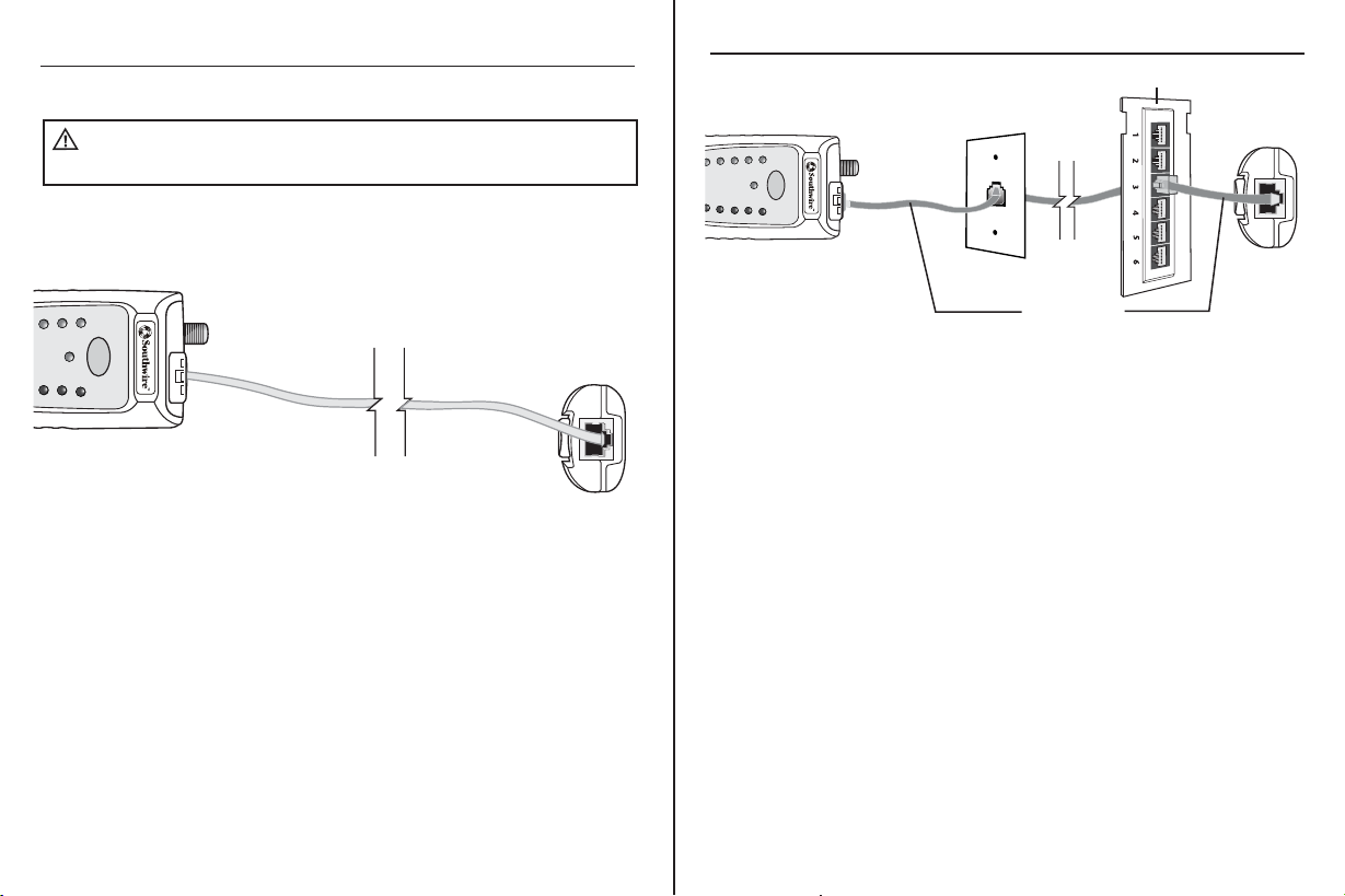
Operation
WiringExamples for Coax Cable
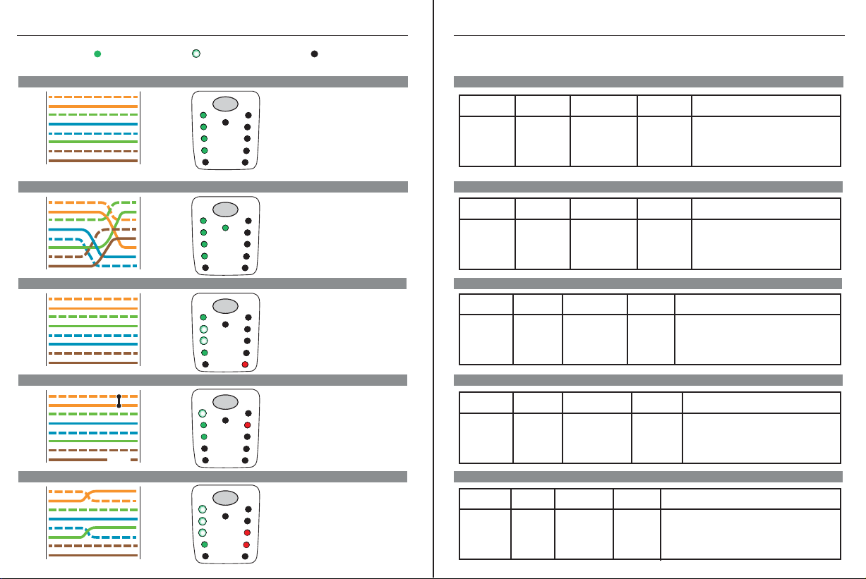
LED status
An LED that does not glow
indicates an open cable
A flashing LED indicates
a shorted cable
An LED that glows indicates
proper continuity
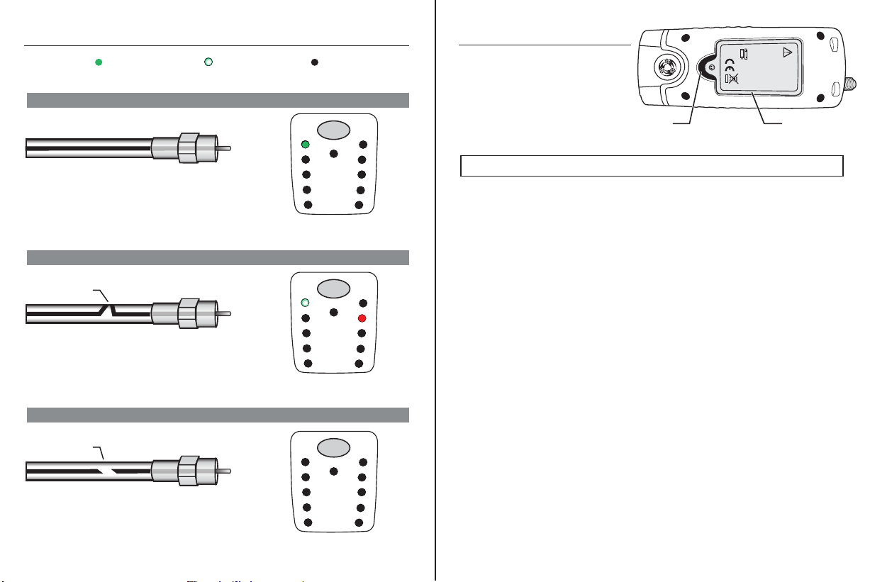
Coax Cable withProper Continuity
The cable is good and passes the test.
TEST
1-2
(coax)
3-6
4-5
7-8
S
X
LOW BATT
SHORT
MISWIRE
REVERSAL
SPLIT
Coax Cable with a Lossof Continuity on the Center Conductoror Shield
There isa break inthe cable causing an opencircuit.
Open
TEST
1-2
(coax)
3-6
4-5
7-8
S
X
LOW BATT
SHORT
MISWIRE
REVERSAL
SPLIT
Coax Cable with a Short Between the CenterConductor and Shield
The center conductor is shorted to the shield.
Short
TEST
1-2
(coax)
3-6
4-5
7-8
S
X
LOW BATT
SHORT
MISWIRE
REVERSAL
SPLIT
Operation
Battery Replacement
NOTE: Do not operate the tester with the battery door removed.
2 x 1.5 “AAA”
Phillips
screwBattery
door
1. Loosen and remove the one
Phillipsscrew.
2. Open the battery compartment.
3. Replace the two AAA batteries.
4. Re-assemble the tester.
Table of contents