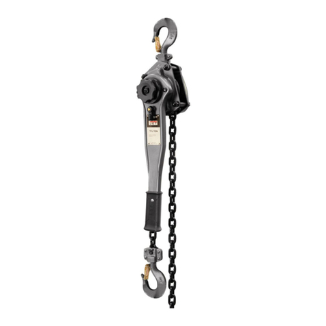
Southwire Sumner LH025 Service manual

SUMNER
OPERATING INSTRUCTIONS AND PARTS MANUAL
STANDARD LEVER OPERATED CHAIN HOIST SERIES
(LH025/LH050/LH075/LH150/LH300/LH600)
READ AND UNDERSTAND ALL
THE INSTRUCTIONS AND SAFETY INFORMATION IN
THIS MANUAL BEFORE OPERATING OR
SERVICING THIS TOOL
LH075
07/19 (LH025/LH050/LH075/LH150/LH300/LH600)
(models shown are representative of the series)
Sumner Manufacturing Co., LLC
7514 Alabonson Road
Houston, Texas 77088
Phone Number: 1.281.999.6900

1
TABLE OF CONTENTS
Important Safety Information .................................................2-5
Description of Operation............................................................6
Specifications (LH025, LH050)
Specifications (LH075, LH150, LH300, LH600)………………....7
Identification...............................................................................8
Inspections.................................................................................9
Operation.............................................................................10-12
Wear Limits..........................................................................13-15
Replacement Parts...................................................................16
LH025 through LH050- Exploded View....................................16
LH025- Parts List......................................................................17
LH050- Parts List………………….……………………….…..….18
LH075 through LH600- Exploded View....................................19
LH075- Parts List......................................................................20
LH150- Parts List......................................................................21
LH300- Parts List......................................................................22
LH600- Parts List......................................................................23
Warranty………………………………………………………..24-25
2
SAFETY ALERT SYMBOLS
These symbols
are used to call attention to hazards or unsafe
practices related that could result in injury or property damage.
The three safety words defined below indicate the severity of the
hazard. The message after the signal word provides information for
preventing or avoiding the hazard.
DANGER - Immediate hazards that if not avoided WILL
result in severe injury or death
WARNING - Hazards that if not avoided COULD result in
severe injury or death
CAUTION - Hazards or unsafe practices that, if not
avoided MAY result in severe injury or death
SAFETY FIRST
Safety is essential in the use and maintenance of Sumner Equipment
This instruction manual and any markings on the tool provide infor-
mation for avoiding hazards and unsafe practices related to the use
of this tool. Observe all the safety information provided.

• Only qualified persons should use the Sumner Standard
Series LH Lever Hoist.
• Wear eye protection, hard hat, cut resistant gloves and safety
toe shoes when using this tool.
• Do not use tool while tired or under the influence of drugs,
alcohol, or medication.
•Keep body parts and loose clothing away from moving parts.
• Always follow safety procedures as shown in this manual.
FAILURE TO OBSERVE THESE WARNINGS CAN
RESULT IN SEVERE INJURY OR DEATH.
FAILURE TO OBSERVE THESE WARNINGS COULD
RESULT IN SEVERE INJURY OR DEATH
WARNING - Personal Safety Hazards
WARNING
• Read and understand all instructions and safety information in
this manual before operating or servicing this tool.
3
IMPORTANT SAFETY INFORMATION
4
IMPORTANT SAFETY INFORMATION
DANGER
:
Electrical Shock Hazards
Entanglement Hazard
Tool Use Hazards
• Use this tool for the manufacturers intended purpose only. Use other
than that described in this manual can result in injury or property damage.
• Only qualified personnel should configure and use the Sumner
Lever Hoist.
•This lever hoist is designed and intended for use by properly trained
and experienced personnel only. If you are not familiar with the proper
and safe operation of a lever hoist, do not use until proper training and
knowledge have been obtained.
• Do not use lever hoist to lift, support or transport people; or to lift
or support loads over people.
• Do not exceed the rated capacity of the hoist.
• Do not attempt to extend the lever handle using a “cheater pipe”
or any other such device.
• Do not strike the lever handle with a hammer or any other object.
•Do not use the chain as a sling. This may cause damage to the chain.
• Always inspect the lever hoist for damage prior to use. If hoist is
damaged, do not use until it has been repaired or replaced.
• Do not use more than one lever hoist to lift or move a load. If this
is unavoidable, each hoist must have the same capacity as the load
to be moved.
• Never allow chain to “set” over sharp edges. All pulls or lifts must
be made with straight chain that is free of obstacles.
• If the lever handle is difficult to operate, then the load exceeds the
capacity of the hoist. Reduce load or select a hoist of larger capacity.
• Do not use hoist if the chain is twisted, kinked or damaged.
WARNING:
• This is not an insulated tool, contact with live circuits could
result in severe injury or death.
• Do not operate this tool while wearing loose fitting clothing.
Retain long hair.
FAILURE TO OBSERVE THESE WARNINGS CAN
RESULT IN SEVERE INJURY OR DEATH.
FAILURE TO OBSERVE THESE WARNINGS CAN
RESULT IN SEVERE INJURY OR DEATH.
WARNING:

• Do not use if any parts are damaged as this can cause an unsafe
condition and lead to tool malfunction or failure.
• If tool is in disrepair, DO NOT USE. Have tool inspected and
repaired prior to use.
5 6
Description of OperationINTRODUCTION
Description of Operation
FAILURE TO OBSERVE THESE CAUTIONS CAN RESULT IN
INJURY OR PROPERTY DAMAGE
CAUTION:
This manual is provided by Sumner covering the safe operation
and maintenance procedures for the Sumner LH Series Lever
Hoists/Pullers. This manual contains instructions on installation,
safety precautions, general operating procedures, maintenance
instructions and parts breakdown. This tool has been designed
and constructed to provide consistent, long-term operation if
used in accordance with instructions set forth in this manual.
The LH Series hoists are all steel construction with a powder coat
finish and have a completely enclosed Weston-type automatic
brake system.
The LH series hoists are proof-tested and comply with OSHA,
ANSI/ASME B30.21 and HST-3 standards.
If there are any questions or comments, please contact either your
local supplier or Sumner Manufacturing. Sumner can also be
reached at our web site: www.sumner.com.
The specifications in this manual were current at time of publica-
tion, but because of our policy of continuous improvement,
Sumner reserves the right to change specifications at any time
and without prior notice, without incurring obligations.
• Do not operate hoist unless load is centered between top and
bottom hooks.
• On hoists with the overload warning lever, do not use this device
to measure load weight.
• Always take time to study the job to be performed and choose
the safest method. Do not place yourself or other people in an
unsafe position.
• Always maintain your balance and firm footing when operating
the lever hoist.
• Leave all internal maintenance and inspections to a qualified
Sumner Service Center.
• Do not attempt to lengthen or repair load chain. Replace chain
with factory replacement chain only. Do not use any other type of
chain.
• If welding near the hoist, do not allow the chain or hook to be
touched by a live electrode. Prevent weld splatter upon the chain.
• Never use the hoist if either hook is stretched, deformed, or has
a broken or missing safety latch. Always replace the safety latch
and/or the hook before placing the hoist back in service.
• Be sure supporting structures and load-attaching devices used
in conjunction with this lever hoist provide an adequate safety
factor to handle the rated load plus the weight of the equipment. If
in doubt, consult a qualified structural engineer.
• Keep visitors a safe distance from the work area. Keep children
away.
• Understand and follow all procedures as set forth in American
National Standards titled “Performance Standard for Manually
Lever Operated Chain Hoists,” ANSI/ASME HST-3; and “Manually
Lever Operated Hoists,” ANSI/ASME B30.21. These standards are
available through the American Society of Mechanical Engineers
at www.asme.org.
PURPOSE OF THIS MANUAL
This manual is intended to familiarize all personnel with the safe
installation and operation of the following:
STANDARD LEVER OPERATED CHAIN HOIST.
Keep this manual available to all personnel. Replacement manuals
are available upon request at no charge at www.sumner.com.
FAILURE TO OBSERVE THESE WARNINGS CAN
RESULT IN SEVERE INJURY OR DEATH.
WARNING:
This product can expose you to chemicals
including lead, which is known to the State of California to cause
cancer and birth defects or other reproductive harm. For more
information go to http://www.p65warnings.ca. gov.

7 8
SPECIFICATIONS
IDENTIFICATION
Support for the hoist may be hook, clevis pin, trolley, or beam
clamp. Whatever method of suspension is chosen, the support
components must be rated equal to, or greater than the capacity
of the lever hoist. Supporting structures (such as I-Beams, etc.)
should be installed by properly licensed professional installers.
WARNING:
Do not operate the hoist with a twisted, kinked
or damaged chain. Do not splice the chain.
LH025/LH050
LH075/LH150/LH300/LH600
Stock
Number
Model
Number
Rated
Capacity
(Ton)
Std.
Lift
(ft.)
Min.
Distance
between
hooks (in.)
"H"
No. of
falls
Load
Chain
(mm)
Lift per
full turn
of lever
(in.)
Pull to
Rated
Load
(lb)
Body
Depth
(in.)
"A"
Diagonal
Body
Width
(in.)
"B"
Centerpoint
Hook Opening
(in.)
"C"
Lever
Length
(in.)
"D"
Hook
Throat
Opening
(in.)
"E"
Net
Weight
(lbs)
787542 LH075C05 0.75 5 12.79 1 6 x 18 0.81 62.94 5.82 10.9 1.45 5.82 1.02 14.08
787543 LH075C10 0.75 10 12.79 1 6 x 18 0.81 62.94 5.82 10.9 1.45 5.82 1.02 17.01
787544 LH075C15 0.75 15 12.79 1 6 x 18 0.81 62.94 5.82 10.9 1.45 5.82 1.02 19.94
787545 LH075C20 0.75 20 12.79 1 6 x 18 0.81 62.94 5.82 10.9 1.45 5.82 1.02 22.87
787546 LH150C05 1.50 5 14.96 1 8 X 24 0.87 85.42 6.77 11.61 1.85 6.77 1.31 24.86
787547 LH150C10 1.50 10 14.96 1 8 X 24 0.87 85.42 6.77 11.61 1.85 6.77 1.31 35.12
787548 LH150C15 1.50 15 14.96 1 8 X 24 0.87 85.42 6.77 11.61 1.85 6.77 1.31 40.25
787549 LH150C20 1.50 20 14.96 1 8 X 24 0.87 85.42 6.77 11.61 1.85 6.77 1.31 45.38
787550 LH300C05 3 5 18.89 1 10 X 30 0.69 70.81 7.87 13.38 2.46 7.87 1.71 42.46
787551 LH300C10 3 10 18.89 1 10 X 30 0.69 70.81 7.87 13.38 2.46 7.87 1.71 50.52
787552 LH300C15 3 15 18.89 1 10 X 30 0.69 70.81 7.87 13.38 2.46 7.87 1.71 58.58
787553 LH300C20 3 20 18.89 1 10 X 30 0.69 70.81 7.87 13.38 2.46 7.87 1.71 67.18
787554 LH600C05 6 5 24.41 2 10 X 30 0.34 74.18 7.87 13.38 3.07 7.87 2.02 68.86
787555 LH600C10 6 10 24.41 2 10 X 30 0.34 74.18 7.87 13.38 3.07 7.87 2.02 78.54
787556 LH600C15 6 15 24.41 210 X 30 0.34 74.18 7.87 13.38 3.07 7.87 2.02 88.22
787557 LH600C20 6 20 24.41 2 10 X 30 0.34 74.18 7.87 13.38 3.07 7.87 2.02 97.90
LH Standard Lever Hoist 3/4 Ton-6 Ton
FIG 1 FIG 2
INSTALLATION
INSPECTION THE CHAIN
Stock
Number
Model
Number
Rated
Capacity
(Ton)
Std.
Lift
(ft.)
Min.
Distance
between
hooks (in.)
"H"
No. of
falls
Load
Chain
(mm)
Lift per
full turn
of lever
(in.)
Pull to
Rated
Load
(lb)
Body
Depth
(in.)
"A"
Body
Width
(in.)
"B"
Centerpoint
Hook Opening
(in.)
"C"
Lever
Length
(in.)
"D"
Hook
Throat
Opening
(in.)
"E"
Net
Weight
(lbs)
787536 LH025C05 1/4 5 8.27 1 4 x 12 1.37 74.86 3.09 2.44 1.39 5.9 0.82 4.18
787537 LH025C10 1/4 10 8.27 1 4 x 12 1.37 74.86 3.09 2.44 1.39 5.9 0.82 5.57
787538 LH025C15 1/4 15 8.27 1 4 x 12 1.37 74.86 3.09 2.44 1.39 5.9 0.82 6.96
787539 LH050C05 1/2 5 10.04 1 4.3 x 12 0.89 104.31 3.74 2.67 1.65 8.46 0.96 8.36
787540 LH050C10 1/2 10 10.04 1 4.3 x 12 0.89 104.31 3.74 2.67 1.65 8.46 0.96 10.01
787541 LH050C15 1/2 15 10.04 1 4.3 x 12 0.89 104.31 3.74 2.67 1.65 8.46 0.96 11.66
LH Standard Lever Hoist 1/4 Ton-1/2 Ton
Lever handle
Selector lever
Safety latch
Top hook
Handwheel
Load chain
Bottom or
“Load”hook

109
FURTHER INSPECTIONS
It is important to check top and bottom hooks for proper opening
and other signs of deformation or damage. Replace a hook imme-
diately if any of t following problems are identified:
• The safety latch no longer contacts the hook opening.
•The vertical angle at the neck of the hook reaches 10°, see (FIG 3).
• Chemical corrosion or cracks on the hook.
• Excessive wear on the inside surface.
• The throat opening has enlarged. See (FIG 13) for the maximum
allowable limits for the throat opening.
• A chain stop must be attached to the second-to-last link on the
slack end of the chain. See (FIG 1) for an example. Do not operate
the hoist with a twisted, kinked or damaged chain. Do not splice
the chain.
•Check that the chain does not twist along its length from hoist to hook.
• Replace the chain if links are stretched too long or seriously worn
on the surface, especially at the points where links contact each other.
See “Allowable Limits” on page14 for measuring chain elongation.
• Do not use a chain that is seriously rusted or cracked.
• Periodically apply a light coat of 30-weight oil to the chain. This
will create easier operation and prolong the chain’s life. For optimum
results, clean the chain with an acid-free solution before oiling.
•Never extend load chain by welding a second piece to the original.
INSPECTING THE HOOK
• With the lever in the up position, while pulling down on the chain
or with a load connected, check for a clicking sound when the
handle is rotated in a clockwise direction. If these sounds are not
present, or if irregular clicking noises develop, do not use the hoist –
have it inspected and repaired by an authorized service center.
• With the lever in the up position, check free play in handle
rotation. Free play is measured by the distance the handle travels
before resistance or gearing is felt. If free play has reached 3/4 of
a turn, brake discs are worn and should be replaced by a Sumner
authorized service center.
• The brake mechanism must be kept clean and free from dirt,
water, and oil. Never allow oil to penetrate the braking mecha-
nism. The brake should not slip while using the hoist.
•If the lever hoist has not been used for an extended period,
check for proper operation before putting into service.
OPERATION
The LH Lever Hoist may be used either in vertical position as a hoist;
or in angled or horizontal position as a puller. Below is the general
procedure for operating the hoist:
•Set the top hook securely.
• Correctly center the load on the bottom hook (FIG 4). Incorrect
loading is dangerous to the operator, the lever hoist, and the load.
• Never load the hook in front of the safety latch (A, FIG 5).
• Never load the hook tip (B, FIG 5).
• Never load the hook off the centerline (C, FIG 5).
• Never load the hook sideways (D, FIG 5).
FIG 3
FIG 4 FIG 5
WARNING:
Do not attempt repair of the hook by heat treating,
bending or attaching anything by welding. Doing so will weaken and
may cause failure of the hook.

1211
OPERATION
• Always keep your hoist clean and store in a clean, dry location.
Place the selector switch on the handle in the center neutral
position (FIG 6). This will allow free-wheel mode. Take up slack by
pulling on loose or free end of chain.
• When finished with freewheel mode (Neutral Position), switch
selector switch to UP or DOWN to re-engage lifting and lowering
modes.
• Move selector switch to the UP position. Ratchet the lever to
raise or pull the load. Do not overload the lever hoist.
• To release or lower the load, turn selector switch on the handle
to the DOWN position and ratchet the handle.
• During pulling operations, the operator should stand near the
side of the top hook on the opposite side from the lever. If the
hand should slip off the lever, the lever will spring back away from
the operator.
• During lifting operations, do not stand under the load.
• Do not use an extension on the lever (FIG 7).
• Do not use a foot to apply pressure to the lever (FIG 8).
• Prevent the chain from dragging over sharp edges or corners.
These will cause links to weaken, bend, or break, (FIG 9).
• When using a wire rope sling, the puller must be applied along a
straight line parallel to the surface on which it is resting (FIG 10).
• When lifting loads, hook the load with slings. Do not use the lever
hoist chain as a sling (FIG 11).
• Both ends of a sling or rope must be completely on the inside of
the safety latch before pulling or lifting the load. Do not put one
end on the inside of the latch and leave the other end on the hook
end outside the latch.
PRECAUTIONS
FIG 6
FIG 7 FIG 8
FIG 9
FIG 10
FIG 11
CAUTION :
Avoid lifting one load with two hoists. If this is
unavoidable, apply equal weight to both hoists and use hoists with
the proper lift capacity. Capacity of each hoist must be equal to the
total load to be lifted.

Capacity
Standard
Throat
Opening
(A)
Standard
Throat
Limit
(A)
0.25 ton 0.82" 0.89"
0.50 ton 0.96" 1.03"
0.75 ton 1.46” 1.61”
1.5 ton 1.85” 2.04”
3ton 2.46” 2.71”
6ton 3.07” 3.38”
1413
• Carefully inspect the entire load chain. As illustrated in (FIG 12),
measure five consecutive links with calipers to find the length,
Compare the results with the table in (FIG 12). Check every three
feet and especially where excessive wear is indicated. Any load
chain that shows noticeable deformation or heat influence must be
replaced with a new one.
FIG 12
FIG 13
WARNING :
Never heat treat the hook or attach anything to
the hook by welding.
INSPECTION
Read and follow ANSI Inspection and Maintenance Instructions.
Know the meaning of Frequent Inspection, Periodic Inspection,
Normal Service, Heavy Service, and Severe Service. It is the
customer’s responsibility to understand and follow all ANSI and
Sumner inspection and maintenance instructions.
The lever hoist should be stored in a clean, dry environment.
Clean and oil the hoist before storage. Hoists that are installed
out-of-doors should be covered or brought inside when not in use.
Periodically apply a light coat of 30 weight oil to the load chain.
Also lubricate the safety latches and the bearings in the hooks.
Annually, the hoist should be disassembled, inspected, and
cleaned by trained and experienced personnel only. Contact a
Sumner authorized service center by calling your dealer or visiting
our web site at www.sumner.com.
WEAR LIMITS LOAD CHAIN
WARNING :
Never extend load chain by welding a second
piece to the original.
INSPECTION
HOOK WEAR LIMITS (TOP and BOTTOM)
• Replace the hook when “A” in (FIG 13) is wider than the “Throat
Opening Limit” shown in the accompanying table.
Capacity
5 Link
Normal
(in)
5 Link
Limit
(in)
0.25 ton 2.36" 2.43"
0.50 ton 2.36" 2.43"
0.75 ton 3.54” 3.65”
1.5 ton 4.72” 4.86”
3 ton 5.91” 6.09”
6 ton 5.91” 6.09”

1615
FIG 14
INSPECTION
• Annual inspection of the brake disk should be performed to
ensure brake disk is within the allowable standards as shown in
(FIG 14).
TIMING MARKS FOR GEAR REPLACEMENT
LH025 through LH050 – EXPLODED VIEW
• If the gears on the LH hoist need replacement or removal for any
reason, make sure they are re-installed correctly. (FIG 15) shows
the proper orientation of the timing marks when meshing the gears.
Replacement parts are listed on the following pages. To order
parts or reach our service department, call 1-281-999-6900
Monday through Friday, 8:00 a.m. to 5:00 p.m. CST. Having the
Model Number and Serial Number of your machine available when
you call will allow us to serve you quickly and accurately.
Non-proprietary parts, such as fasteners, can be found at local
hardware stores. McMaster- Carr reference numbers are provided
for hardware specifications. Some parts are shown for reference
only and may not be available individually.
REPLACEMENT PARTS
FIG 15
d = inner diameter
D = outer diameter
tn = normal measurement
tv = replacement limit

17 18
LH025 Quanty Stock # Reference MODEL DESCRIPTION UPC
1 1 788200McMaster
90967A115KX050-29 Snap Ri ng 661165882001
2 1 788201KX050-28 Hand Wheel661165882018
3 1 788202KX025-27 Stop Knob 661165882025
4 1 788203McMaster
90967A270YAL025-4 Snap Ring 661165882032
5 1 788204 YAL050-5 Lever Handle Assembly 661165882049
6 1 788205KX050-23 Change Over Gear 661165882056
7 1 788206KX050-22 Bushing 661165882063
8A 1 788207McMaster
90591A255YAL050-8A Hexagon Nut = Zinc-Plated Steel Hex Nut, Medium-
Strength, Class 8, M4 x 0.7 mm Thread 661165882070
8B 1 788208McMaster
91202A230YAL050-8B Lock Washer = Zinc-Plated Steel Split Lock Washer
for M5 Screw Size, 5.4 mm ID, 9.2 mm OD 661165882087
9 1 788209 YAL025-9 Brake Cover 661165882094
10 1 788210KX050-33 Disc Hub 661165882100
11 1 788211KX050-18 Twisng Spring 661165882117
12 2 788212 YAL025-12 Fricon Disc 661165882124
13 1 788213KX050-17 Ratchet Disc 661165882131
14 2 788214McMaster
90967A110KX050-16 Snap Ri ng 661165882148
15 2 788215KX050-15 Pawl 661165882155
16 2 788216KX050-14 Pawl Spri ng 661165882162
17 1 788217 YAL025-17 Brake Seat 661165882179
18 1 788218 YAL025-18 Lever Side Pl ate Assembly 661165882186
19 2 788219 YAL025-19 Guide Roller 661165882193
20 1 788220 YAL025-20 Load Sheave 661165882209
21 1 788221 YAL025-21 Top Hook Assembly 661165882216
22 2 788222 YAL025-22 Safety Latch Assembly 661165882223
23 1 788223KX025-3 Top Hook Sha661165882230
24 1 788224 YAL025-24 Pin 661165882247
25 1 788225 YAL025-25 Gear Si de Plate 661165882254
26 1 788226 YAL025-26 Gear Cover 661165882261
27A 2 788227McMaster
91202A230YAL025-27A Lock Washer 661165882278
27B 2 788228McMas ter
94387A341YAL025-27B Phillips Pan Head Screw = JIS Steel Pan Head
Phillips Screws, M5 x 0.8 mm Thread, 35 mm Long 661165882285
28A 1 788227McMaster
91202A230YAL025-27A Lock Washer 661165882278
28B 1 788229McMas ter
92095A210YAL025-28B
Socket Head Screw = Buon Head Hex Drive Screw,
Passivated 18-8 Stainless Steel, M5 x 0.80 mm
Thread, 12mm Long
661165882292
29 1 788230 YAL025-29 Stripper 661165882308
30 2 788231 YAL025-30 Stay Bolt 661165882315
31 1 788232 YAL025-31 Support 661165882322
32 1 788233 YAL025-32 Stay Bolt II 661165882339
33A 2 788227McMaster
91202A230YAL025-27A Lock Washer 661165882278
33B 2 788234McMas ter
91180A037YAL025-33B Acorn nut = Low-Strength Steel Cap Nut, Zinc-
Plated, M5 x 0.8 mm Thread 661165882346
34A 1 788235 KV016-27A Steel Pan Head Phillips Screw, M3.5 x 0.6 mm
Thread, 6 mm Long 661165882353
34B 1 788236KX025-30B Barrel Nut - M3 x 11.5 x 5Ф661165882360
35 1 788237KX050-31 Rubber Grip 661165882377
36 As Req'd
Per Foot 788238Φ4×12 Load Chai n 661165882384
37 1 788239 YAL050-37 End Chain Ring 661165882391
38A 1 788240 YAL025-38A Load Pin 661165882407
38B 1 788241 YAL050-38B Lock Nut 661165882414
39 1 788242 YAL025-39 Boom Hook Assembly 661165882421
LH050 Quanty Stock # Reference MODEL DESCRIPTION UPC
1 1 788200
McMaster
90967A115
KX050-29 Snap Ring 661165882001
2 1 788201KX050-28 Hand Wheel661165882018
3 1 788243 YAL075-1 Stop Knob 661165882438
4 1 788244
McMaster
98541A130
YAL050-4 Snap Ring 661165882445
5 1 788204 YAL050-5 Lever Handle Assembly 661165882049
6 1 788245 YAL050-6 Change Over Gear 661165882452
7 1 788246 YAL050-7 Bus hing 661165882469
8A 1 788207McMaster
90591A255YAL050-8A Hexagon Nut = Zinc-Plated Steel Hex Nut,
Medium-Strength, Cl ass 8, M4 x 0.7 mm Thread 661165882070
8B 1 788208McMaster
91202A230YAL050-8B
Lock Washer = Zinc-Plated Steel Split Lock
Washer for M5 Screw Size, 5.4 mm ID, 9.2 mm
OD
661165882087
9 1 788247 YAL050-9 Brake Cover 661165882476
10 1 788248 YAL050-10 Disc Hub 661165882483
11 1 788249 YAL050-11 Twisng Spring 661165882490
12 2 788250 YAL050-12 Fricon Di sc 661165882506
13 1 788251 YAL050-13 Ratchet Disc 661165882513
14 2 788214
McMaster
93279A100
KX050-16 Snap Ring 661165882148
15 2 788215KX050-15 Pawl 661165882155
16 2 788216KX050-14 Pawl Spring 661165882162
17 1 788252 YAL050-17 Brake Seat 661165882520
18 1 788253 YAL050-18 Lever Si de Plate Assembly 661165882537
19 2 788254 YAL050-19 Guide Roller 661165882544
20 1 788255 YAL050-20 Load Sheave 661165882551
21 1 788256 YAL050-21 Top Hook Assembly 661165882568
22 2 788257 YAL050-22 Safety Latch Assembly 661165882575
23 1 788258KX050-3 Top Hook Sha661165882582
24 1 788259 YAL050-24 Pin 661165882599
25 1 788260 YAL050-25 Gear Side Plate 661165882605
26 1 788261 YAL050-26 Gear Cover 661165882612
27A 2 788262
McMaster
93279A100
YAL050-27A Lock Was her 661165882629
27B 2 788263McMaster
92095A248YAL050-27B
Socket Head Screw = Buon Head Hex Drive
Screw, Passi vated 18-8 Stainless Steel, M6 x 1
mm Thread, 40mm Long
661165882636
28A 1 788262
McMaster
93279A100
YAL050-27A Lock Was her 661165882629
28B 1 788264McMaster
92095A224YAL050-28B
Socket Head Screw = Buon Head Hex Drive
Screw, Passi vated 18-8 Stainless Steel, M6 x 1
mm Thread, 10mm Long
661165882643
29 1 788265 YAL050-29 Stripper 661165882650
30 2 788266 YAL050-30 Stay Bol t 661165882667
31 1 788267 YAL050-31 Support 661165882674
32 1 788268 YAL050-32 Stay Bol t II 661165882681
33A 1 788262
McMaster
93279A100
YAL050-27A Lock Was her 661165882629
33B 1 788269
McMaster
99164A101
YAL050-33B
Acorn nut = High-Strength SteelCap Nut, Class
10, Zinc-Plated, M6 x 1 mm Thread
661165882698
34A 1 788235 KV016-27A
Steel Pan Head Phillips Screw, M3.5 x 0.6 mm
Thread, 6 mm Long
661165882353
34B 1 788236KX025-30B Barrel Nut - M3 x 11.5 x 5Ф661165882360
35 1 788270 YAL050-35 Rubber Grip 661165882704
36
As Req'd
Per Foot
788271Φ4.3×12 Load Chain 661165882711
37 1 788239 YAL050-37 End Chai n Ring 661165882391
38A 1 788272KX050-39A Load Pi n 661165882728
38B 1 788241 YAL050-38B Lock Nut 661165882414
39 1 788273KX050-40 Boom Hook Assembly 661165882735

LH075 through LH600 – EXPLODED VIEW
19 20
LH075 Quanty Stock # Reference MODEL DESCRIPTION UPC
1 1 788243 YAL075-1 Stop Knob 661165882438
2 1 788274 YAL075-2 Lever Handle Assembly 661165882742
3 1 788275 YAL075-3 Change Over Gear 661165882759
8788276McMaster
91202A238TB300-4B
Lock Washer = Zinc-Plated Steel Split Lock
Washer for M8 Screw Size, 8.5 mm ID, 14.8 mm
OD
661165882766
8788277McMaster
99164A102TB300-4A Acorn Nut = High-Strength Steel Cap Nut, Class
10, Zinc-Plated, M8 x 1.25mm Thread 661165882773
5 1 788278 YAL075-5 Brake Cover As sembly 661165882780
6 2 788279 YAL075-6 Fricon Disc 661165882797
7 1 788280 YAL075-7 Ratchet Disc 661165882803
8 1 788281 YAL150-8 Twisng Spring 661165882810
9 1 788282 YAL075-9 Brake Seat 661165882827
10 2 788283McMaster
90967A155YAL150-10 Snap Ring = External Retaining Ring for 9 mm
OD, DIN 1.4122 Stainles sSteel661165882834
11 2 788284 YAL150-11 Pawl 661165882841
12 2 788285 YAL150-12 Pawl Spring 661165882858
13 1 788286 YAL075-13 Lever Handle Side Plate Assembly 661165882865
14 1 788287 YAL075-14 Load Sprocket 661165882872
2788288 YAL075-15 Top Hook Holder 661165882889
0LeTop Hook Holder
0 Right Top Hook Holder
16 1788289YAL075-16 Drive Sha661165882896
17 2 788290 YAL075-17 Safety Latch Assembly 661165882902
18 1 788291 YAL075-18 Top Hook Assembly 661165882919
19 1 788292 YAL075-19 Chain Guide Plate 661165882926
20 1 788293 YAL075-20 Top Hook Sha661165882933
21 1 788294 YAL075-21 Gear Side Plate Assembly 661165882940
22 1 788295 YAL075-22 Load Gear 661165882957
23 1 788296McMaster
90967A241YAL075-23 Snap Ring = External Retaining Ring for 22 mm
OD, DIN 1.4122 Stainles sSteel661165882964
24 2 788297 YAL075-24 Spur Gear As sembly 661165882971
25 1 788298 YAL075-25 Gear Cover Assembly 661165882988
26 1 788299 YAL075-26 Capacity Nameplate 661165882995
27 1 788300 YAL075-27 Stripper 661165883008
28 2 788301 YAL075-28 Boom Hook Holder 661165883015
29 2 788302 YAL075-29 Caged Roller Bearings 661165883022
30 1 788303McMaster
90576A115TB050-30B Lock Nut 661165883039
31 As Req'd 788304Ф6X18 Load chain 661165883046
3788305McMaster
91280A324YAL075-32A
Hex Head Cap Screw = Medium-Strength Class
8.8 Steel Hex Head Screw, Zinc-Plated, M6 x 1
mm Thread, 12 mm Long
661165883053
3788306McMaster
91202A234YAL075-32B Lock Washer 661165883060
33 1 788307 YAL075-33 HandWheel661165883077
34 1 788308McMaster
98350A160K500-32B Split Pin = Coer Pin, Zinc-Plated Steel, 2mm
Diameter, 20mm Long 661165883084
35 1 788349McMaster
93760A222K500-26
Pinion Nut - Castle Nut
Steel Locknut for Use with Coer Pins, Medium-
Strength, Class8, M8 x 1.25mm Thread
661165883497
6788310McMaster
97358A101K500-1 661165883107
0788309 N/A
37 1 788311 YAL075-37 NamePlate 661165883114
38 1 788312 YAL075-38 Rubber Grip 661165883121
39 1 788313 YAL075-39 Change Over Gear 661165883138
40 1 788314 YAL075-40 Spring Sha661165883145
41 1 788315 YAL075-41 Change Over Spring 661165883152
42 1 788316 YAL075-42 Boom Hook Assembly 661165883169
43 1 788317 YAL075-43 Load Pin 661165883176
44 1 788933 YAL075-44 EndChain Grip 661165889338
45 0 Lock Nut
46 0 Load Pin
47 0 Lock Nut
48 0 Socket Cap Screw
49 0 Idle Sheave
0
0
0
0
52 0 Cylinder Pin
53 0 Socket Cap Screw
54 0 Lock Nut
55 0 Lock Nut
56 0 Socket Cap Screw
4
15
32
36
50
51
Rivet = Low-Profile Flat Head Solid Rivets,
0.119" Diameter, for 0.16" Maximum Material
Thickness
Idle Sha
Needle Bearing

21 22
LH150 Quanty Stock # Reference MODEL DESCRIPTION UPC
1 1 788319 YAL300-1 Stop Knob 661165883190
2 1 788320 YAL300-2 Lever Handle Assembly 661165883206
3 1 788321 YAL150-3 Change Over Gear 661165883213
8788322McMaster
91202A242TB500-4B
Lock Washer = Zinc-Plated Steel Split Lock Washer
for M10Screw Size, 10.7 mm ID, 18.1 mm OD 661165883220
8788323McMaster
99164A103TB500-4A Acorn Nut = High-Strength Steel Cap Nut, Class10,
Zinc-Plated, M10x 1.5 mm Thread 661165883237
5 1 788324 YAL150-5 Brake Cover Assembly 661165883244
6 2 788325 YAL300-6 Fricon Disc 661165883251
7 1 788326 YAL300-7 Ratchet Disc 661165883268
8 1 788281 YAL150-8 Twisng Spring 661165882810
9 1 788327 YAL300-9 Brake Seat 661165883275
10 2 788283McMaster
90967A155YAL150-10 Snap Ring = External Retaining Ring for 9 mm OD,
DIN 1.4122 StainlessSteel661165882834
11 2 788284 YAL150-11 Pawl 661165882841
12 2 788285 YAL150-12 Pawl Spring 661165882858
13 1 788328 YAL150-13 Lever Handle Side Plate As sembly 661165883282
14 1 788329 YAL150-14 Load Sprocket 661165883299
2788330 YAL150-15 Top Hook Holder 661165883305
0788309 N/A LeTop Hook Holder
0788309 N/A Right Top Hook Holder
16 1 788331 YAL150-16 Drive Sha661165883312
17 2 788332 YAL150-17 Safety Latch Assembly 661165883329
18 1 788333 YAL150-18 Top Hook Assembly 661165883336
19 1 788334 YAL150-19 Chain Guide Plate 661165883343
20 1 788335 YAL150-20 Top Hook Sha661165883350
21 1 788336 YAL150-21 Gear Side Plate Assembly 661165883367
22 1 788337 YAL150-22 Load Gear 661165883374
23 1 788296McMaster
90967A241YAL075-23 Snap Ring = External Retaining Ring for 22 mm OD,
DIN 1.4122 StainlessSteel661165882964
24 2 788338 YAL150-24 Spur Gear Assembly 661165883381
25 1 788339 YAL150-25 Gear Cover Assembly 661165883398
26 1 788340 YAL150-26 Capacity Nameplate 661165883404
27 1 788341 YAL150-27 Stripper 661165883411
28 2 788342 YAL150-28 Boom Hook Holder 661165883428
29 2 788343 YAL150-29 Caged Roller Bearings 661165883435
30 1 788344McMaster
90576A115TB100-30B Lock Nut = Medium-Strength Steel Nylon-Insert
Locknut, Class8, Zinc-Plated, M6 x 1 mm Thread 661165883442
31 As Req'd
Per Foot 788345Ф8X24 Load chain 661165883459
3788346McMaster
91280A526YAL300-32
Hex Head Cap Screw = Medium-Strength Class8.8 Steel
Hex Head Screw, Zinc-Plated, M8 x 1.25mmThread, 16
mm Long
661165883466
3788347McMaster
91202A238YAL300-4B
Lock Washer = Zinc-Plated Steel Split Lock Washer for
M8 Screw Size, 8.5 mm ID, 14.8 mm OD 661165883473
33 1 788348 YAL300-33 HandWheel661165883480
34 1 788308McMaster
98350A160K500-32B Split Pin = Coer Pin, Zinc-Plated Steel, 2mm
Diameter, 20mm Long 661165883084
35 1 788349McMaster
93760A222K500-26
Pinion Nut - Castle Nut
Steel Locknut for Use with Coer Pins, Medium-
Strength, Class8, M8 x 1.25mm Thread
661165883497
0 NA
4788310McMaster
97358A101K500-1 661165883107
37 1 788350 YAL150-37 NamePlate 661165883503
38 1 788351 YAL300-38 Rubber Grip 661165883510
39 1 788352 YAL300-39 Change Over Gear 661165883527
40 1 788353 YAL300-40 Spring Sha661165883534
41 1 788354 YAL300-41 Change Over Spring 661165883541
42 1 788355 YAL150-42 Boom Hook Assembly 661165883558
43 1 788356 YAL150-43 Load Pin 661165883565
44 1 788933 YAL150-44 EndChain Grip 661165889338
45 0 Lock Nut
46 0 Load Pin
47 0 Lock Nut
48 0 Socket Cap Screw
49 0 Idle Sheave
0
0
0
0
52 0 Cylinder Pin
53 0 Socket Cap Screw
54 0 Lock Nut
55 0 Lock Nut
56 0 Socket Cap Screw
51
Rivet = Low-Profile Flat Head Solid Rivets, 0.119"
Diameter, for 0.16" Maximum Material Thickness
Idle Sha
Needle Bearing
4
15
32
36
50
LH300 Quanty Stock # Reference MODEL DESCRIPTION UPC
1 1 788319 YAL300-1 Stop Knob 661165883190
2 1 788320 YAL300-2 Lever Handle Assembly 661165883206
3 1 788321 YAL150-3 Change Over Gear 661165883213
8788347McMaster
91202A246YAL300-4B
Lock Washer = Zinc-Plated Steel Split Lock Washer
for M12Screw Size, 12.7 mm ID, 21.1 mm OD 661165883473
8788357McMaster
99164A104YAL300-4A Acorn Nut = High-Strength Steel Cap Nut, Class10,
Zinc-Plated, M12x 1.75mm Thread 661165883572
5 1 788358 YAL300-5 Brake Cover Assembly 661165883589
6 2 788325 YAL300-6 Fricon Disc 661165883251
7 1 788326 YAL300-7 Ratchet Disc 661165883268
8 1 788359 YAL300-8 Twisng Spring 661165883596
9 1 788327 YAL300-9 Brake Seat 661165883275
10 2 788360McMaster
98541A445YAL300-10 Snap Ring = External Retaining Ring for 11 mm OD,
Black-Phosphate 1060-1090 Spring Steel661165883602
11 2 788361 YAL300-11 Pawl 661165883619
12 2 788362 YAL300-12 Pawl Spring 661165883626
13 1 788363 YAL300-13 Lever Handle Side Plate Assembly 661165883633
14 1 788364 YAL300-14 Load Sprocket 661165883640
2788365 YAL300-15 Top Hook Holder 661165883657
0788309 N/A LeTop Hook Holder
0788309 N/A Right Top Hook Holder
16 1 788366 YAL300-16 Drive Sha661165883664
17 2 788367 YAL300-17 Safety Latch Assembly 661165883671
18 1 788368 YAL300-18 Top Hook Assembly 661165883688
19 1 788369 YAL300-19 Chain Guide Plate 661165883695
20 1 788370 YAL300-20 Top Hook Sha661165883701
21 1 788371 YAL300-21 Gear Side Plate Assembly 661165883718
22 1 788372 YAL300-22 Load Gear 661165883725
23 1 788373McMaster
90967A312YAL300-23 Snap Ring = External Retaining Ring for 32 mm OD,
DIN 1.4122 StainlessSteel661165883732
24 2 788374 YAL300-24 Spur Gear Assembly 661165883749
25 1 788375 YAL300-25 Gear Cover Assembly 661165883756
26 1 788376 YAL300-26 Capacity Nameplate 661165883763
27 1 788377 YAL300-27 Stripper 661165883770
28 2 788378 YAL300-28 Boom Hook Holder 661165883787
29 2 788379 YAL300-29 Caged Roller Bearings 661165883794
30 1 788380McMaster
90576A118TB300-30B
Lock Nut = Medium-Strength Steel Nylon-Insert
Locknut, Class8, Zinc-Plated, M10x 1.5 mm Thread 661165883800
31 As Req'd Per
Foot 788381Ф10X30 Load chain 661165883817
3788346McMaster
91280A526YAL300-32
Hex Head Cap Screw = Medium-Strength Class8.8 Steel
Hex Head Screw, Zinc-Plated, M8 x 1.25mm Thread, 16
mm Long
661165883466
3788347McMaster
91202A238YAL300-4B
Lock Washer = Zinc-Plated Steel Split Lock Washer for
M8 Screw Size, 8.5 mm ID, 14.8 mm OD 661165883473
33 1 788348 YAL300-33 HandWheel661165883480
34 1 788308McMaster
98350A160K500-32B Split Pin = Coer Pin, Zinc-Plated Steel, 2mm
Diameter, 20mm Long 661165883084
35 1 788349McMaster
93760A222K300-26
Pinion Nut - Castle Nut
Steel Locknut for Use with Coer Pins, Medium-
Strength, Class8, M8 x 1.25mm Thread
661165883497
0 NA
4788310McMaster
97358A101K500-1 661165883107
37 1 788382 YAL300-37 NamePlate 661165883824
38 1 788351 YAL300-38 Rubber Grip 661165883510
39 1 788352 YAL300-39 Change Over Gear 661165883527
40 1 788353 YAL300-40 Spring Sha661165883534
41 1 788354 YAL300-41 Change Over Spring 661165883541
42 1 788383 YAL300-42 Boom Hook Assembly 661165883831
43 1 788384 YAL300-43 Load Pin 661165883848
44 1 788318 YAL300-44 EndChain Grip 661165883183
45 0 Lock Nut
46 0 Load Pin
47 0 Lock Nut
48 0 Socket Cap Screw
49 0 Idle Sheave
0
0
0
0
52 0 Cylinder Pin
53 0 Socket Cap Screw
54 0 Lock Nut
55 0 Lock Nut
56 0 Socket Cap Screw
51
Rivet = Low-Profile Flat Head Solid Rivets, 0.119"
Diameter, for 0.16" Maximum Material Thickness
Idle Sha
Needle Bearing
4
15
32
36
50

23 24
WARRANTY ON
SUMNER EQUIPMENT
What Does This Warranty Cover?
Limited Lifetime Warranty on Sumner Equipment
Under Sumner’s Equipment Limited Lifetime Warranty, Sumner Manufacturing Co., LLC
warrants that all Sumner Equipment will be free from manufacturer defects for a Limited
Lifetime except for moving parts deemed consumables from the date of the original end
user’s purchase. Products deemed as consumable products, components and parts such
as steel cables, rollers, bearings, wheels, lift mast sections components are excluded from
this Limited Lifetime Warranty and are subject to One -Year Limited Warranty terms. Sumner
electrical components are excluded from this Limited Lifetime Warranty and are subject to
One -Year Limited Warranty terms. Under this Limited Lifetime Warranty, the following are
also excluded, and Sumner will have no liability for any of the following: normal wear and
tear resulting from product use and damage arising out of misuse, abuse, modification, and
improper product maintenance. This warranty also does not cover Sumner’s Equipment
products that have been modified by any party other than Sumner or its authorized
third-party designee. This Limited Lifetime Warranty is not transferrable to or enforceable by
any person other than the product’s original end user.
Three-Year Limited Warranty on Pallet Jacks and Hydraulic Tools
Under Sumner’s 3-Year Limited Warranty, Sumner Manufacturing Co., LLC warrants that all
Sumner Pallet Jacks and Hydraulic Tools will be free from manufacturer defects for a period
of three (3) years from the date of the original end user’s purchase. Under this Three-Year
Limited Warranty for Pallet Jacks and Hydraulic Tools, the following are excluded and
Sumner Manufacturing Co., LLC will have no liability for any of the following: normal wear
and tear resulting from product use and damage arising out of misuse, abuse, modification,
and improper product maintenance. This warranty also does not cover Pallet Jacks and
Hydraulic Tools that have been modified by any party other than Sumner Manufacturing Co.,
LLC or its authorized third-party designee. This 3-Year Limited Warranty is not transferrable
to or enforceable by any person other than the product’s original end user.
One-Year Limited Warranty on All Products
Under Sumner’s 1-Year Limited Warranty, Sumner Manufacturing Co., LLC warrants that all
products will be free from manufacturer defects for a period of one-year from the date of the
original end user’s purchase. Under this 1-Year Limited Warranty, Sumner Manufacturing
Co., LLC will have no liability for any of the following: normal wear and tear resulting from
product use and damage arising out of misuse, abuse, modification, and improper product
maintenance. This warranty also does not cover Sumner Equipment that has been modified
by any party other than Sumner Manufacturing Co., LLC or its authorized third-party
designee. This 1-Year Limited Warranty is not transferable to or enforceable by any person
other than the product’s original end user.
Exclusion of Incidental, Consequential, Indirect, Special and Punitive Damages
SUMNER MANUFACTURING CO. LLC MAKES NO WARRANTY THAT SUMNER MANUFAC-
TURING CO. LLC PRODUCTS WILL BE MERCHANTABLE OR FIT FOR ANY PARTICULAR
PURPOSE. SUMNER MAKES NO OTHER WARRANTY, EXPRESSED OR IMPLIED, OTHER
THAN THE RELEVANT WARRANTY SPECIFICALLY SET FORTH IN THIS WARRANTY
SECTION. SOUTHWIRE WILL NOT BE LIABLE FOR ANY INCIDENTAL, CONSEQUENTIAL,
INDIRECT, SPECIAL, OR PUNITIVE DAMAGES FOR ANY BREACH OF THIS LIMITED
LIFETIME WARRANTY.
LH600 Quanty Stock # Reference MODEL DESCRIPTION UPC
1 1 788319 YAL300-1 Stop Knob 661165883190
2 1 788320 YAL300-2 Lever Handle Assembly 661165883206
3 1 788321 YAL150-3 Change Over Gear 661165883213
8788347McMaster
91202A246 YAL300-4B Lock Washer = Zinc-Plated Steel Split Lock Washer for M12 ScrewSize,
12.7 mm ID, 21.1 mm OD 661165883473
8788357McMaster
99164A104 YAL300-4A Acorn Nut = High-Strength Steel Cap Nut, Class 10,
Zinc-Plated, M12 x 1.75 mm Thread 661165883572
5 1 788358 YAL300-5 Brake Cover Assembly 661165883589
6 2 788325 YAL300-6 Fricon Disc 661165883251
7 1 788326 YAL300-7 Ratchet Disc 661165883268
8 1 788359 YAL300-8 Twisng Spring 661165883596
9 1 788327 YAL300-9 Brake Seat 661165883275
10 2 788360McMaster
98541A445 YAL300-10 Snap Ring = External Retaining Ring for 11 mm OD,
Black-Phosphate 1060-1090Spring Steel 661165883602
11 2 788361 YAL300-11 Pawl 661165883619
12 2 788362 YAL300-12 Pawl Spring 661165883626
13 1 788363 YAL300-13 Lever Handle Side Plate Assembly 661165883633
14 1 788364 YAL300-14 Load Sprocket 661165883640
0788309 N/A Top Hook Holder
1788385 YAL600-15A LeTop Hook Holder 661165883855
1788386 YAL600-15B Right Top Hook Holder 661165883862
16 1 788366 YAL300-16 Drive Sha661165883664
17 2 788387 YAL600-17 Safety Latch Assembly 661165883879
18 1 788388 YAL600-18 Top Hook Assembly 661165883886
19 1 788369 YAL300-19 Chain Guide Plate 661165883695
20 1 788370 YAL300-20 Top Hook Sha661165883701
21 1 788371 YAL300-21 Gear Side Plate Assembly 661165883718
22 1 788372 YAL300-22 Load Gear 661165883725
23 1 788373McMaster
90967A312 YAL300-23 Snap Ring = External Retaining Ring for 32 mm OD,
DIN 1.4122 Stainless Steel 661165883732
24 2 788374 YAL300-24 Spur Gear Assembly 661165883749
25 1 788375 YAL300-25 Gear Cover Assembly 661165883756
26 1 788389 YAL600-26 Capacity Nameplate 661165883893
27 1 788377 YAL300-27 Stripper 661165883770
28 2 788390 YAL600-28 Boom Hook Holder 661165883909
29 2 788379 YAL300-29 Caged Roller Bearings 661165883794
30 0 788309 N/A Lock Nut
31 As Req'd
Per Foot 788381Ф10X30 Load chain 661165883817
3788346McMaster
91280A526 YAL300-32
Hex Head Cap Screw = Medium-Strength Class 8.8 Steel Hex Head
Screw, Zinc-Plated, M8 x 1.25 mm
Thread, 16 mm Long
661165883466
3788347McMaster
91202A238 YAL300-4B Lock Washer = Zinc-Plated Steel Split Lock Washer for M8 Screw Size,
8.5 mm ID, 14.8 mm OD 661165883473
33 1 788348 YAL300-33 Hand Wheel 661165883480
34 1 788308McMaster
98350A160 K500-32B Spli t Pin = Coer Pin, Zinc-Plated Steel, 2mm
Diameter, 20mm Long 661165883084
35 1 788349McMaster
93760A222 K300-26
Pinion Nut - Castle Nut
Steel Locknut for Use with Coer Pins, Medium-Strength, Class 8,
M8 x 1.25 mm Thread
661165883497
0
4788310McMaster
97358A101 K500-1 661165883107
37 1 788391 YAL600-37 NamePlate 661165883916
38 1 788351 YAL300-38 Rubber Grip 661165883510
39 1 788352 YAL300-39 Change Over Gear 661165883527
40 1 788353 YAL300-40 Spring Sha661165883534
41 1 788354 YAL300-41 Change Over Spring 661165883541
42 1 788392 YAL600-42 Boom Hook Assembly 661165883923
43 1 788309 N/A Load Pin #N/A
44 1 788318 YAL300-44 End Chain Grip 661165883183
45 2 788380McMaster
90576A118 TB300-30B Lock Nut = Medium-Strength Steel Nylon-Insert Locknut, Class 8, Zinc-
Plated, M10 x 1.5 mm Thread 661165883800
46 1 788393 YAL600-46 Load Pin 661165883930
47 3 788344McMaster
90576A115 TB100-30B Lock Nut 661165883442
48 3 788394McMaster
91280aA546 YAL600-48
Hex Head Cap Screw = Medium-Strength Class 8.8 Steel Hex Head
Screw, Zinc-Plated, M8 x 1.25 mm
Thread, 50 mm Long
661165883947
49 1 788395 YAL600-49 Idle Sheave 661165883954
1788396 YAL600-50 661165883961
0 N/A
29 788397Ф3X40 661165883978
0 N/A
52 0 N/A Cylinder Pin
53 1 788398McMaster
91280A538 TB500-43A
Hex Head Cap Screw = Medium-Strength Class 8.8 Steel Hex Head
Screw, Zinc-Plated, M8 x 1.25 mm
Thread, 30 mm Long
661165883985
54 1 788344McMaster
90576A115 TB100-30B Lock Nut = Medium-Strength Steel Nylon-Insert Locknut, Class 8,Zinc-
Plated, M6 x 1 mm Thread 661165883442
55 2 788380McMaster
90576A118 TB300-30B Lock Nut = Medium-Strength Steel Nylon-Insert Locknut, Class 8, Zinc-
Plated, M10 x 1.5 mm Thread 661165883800
56 2 788399McMaster
91280A634 K500-53
Socket Cap Screw = Medium-Strength Class 8.8 Steel Hex Head Screw,
Zinc-Plated, M10 x 1.5 mm
Thread, 30 mm Long
661165883992
51
Rivet = Low-Profile Flat Head Solid Rivets, 0.119" Diameter, for 0.16"
Maximum Material Thickness
Idle Sha
Needle Bearing
4
15
32
36
50

Warranty Claim Information/How Do You Get Service?
Sumner Manufacturing Co., LLC
7514 Alabonson Road
Houston, Texas 77088
Phone Number: 1.281.999.6900
Sumner – Canada
75 Saltman Drive, Unit 5
Cambridge, Ontario N3H 4R7
Phone Number: 1.519.651.5300
Sumner – U.K.
Unit 3 Kepton Road
Keytec 7 Business Park
Pershore Worcestershire
WR10 2TA, UK
Phone Number: +44 (0) 1386 556278
Sumner – Netherlands
Handelsweg 26
3881LS Putten
The Netherlands
Repair Your Product When it is Out of Warranty
Southwire is happy to provide information about where a purchaser can send a product for
repair at consumers’ own expense, please contact 1.281.999.6900 or visit www.sumner.com
for more information about servicing for Sumner Products.
1. All warranty claims must be approved by Sumner’s Warranty Department prior to return of
product. If Sumner determines that a product is defective, Sumner will, at its option, repair or
replace defective products or defective product components, free of charge.
2. Upon approval, Sumner will issue a Product Return Authorization Form which will include
instructions on how and where to return the product. The product serial number and the
original date of delivery must be set forth on the Product Return Authorization Form.
3. Sumner will cover standard freight charges (Courier Ground rate) incurred in connection
with products that Sumner ultimately determines to be defective.
4. All defective components and defective products that Sumner replaces under these
Warranties will become Sumner’s property and will be retained by Sumner.
Some states do not allow the exclusion or limitation of incidental or consequential
damages, so the above limitation or exclusion may not apply to you.
Phone Number: +31 (0) 85 489 0284
For all warranty, customer service, and product return authorizations and inquiries, please
contact Sumner at:
25
Notes
________________________________________________________________________
_________________________________________________________________________
_________________________________________________________________________
_________________________________________________________________________
_________________________________________________________________________
_________________________________________________________________________
_________________________________________________________________________
_________________________________________________________________________
_________________________________________________________________________
_________________________________________________________________________
_________________________________________________________________________
_________________________________________________________________________
_________________________________________________________________________
_________________________________________________________________________
_________________________________________________________________________
_________________________________________________________________________
_________________________________________________________________________
_________________________________________________________________________
_________________________________________________________________________
_________________________________________________________________________
_________________________________________________________________________
_________________________________________________________________________
26
This manual suits for next models
4
Table of contents
Popular Chain Hoist manuals by other brands

McBULL
McBULL 9320 manual

Tractel
Tractel tralift 0.5 t. Operating and maintenance instruction

Ingersoll-Rand
Ingersoll-Rand KX Series Product Maintenance Information

MODE
MODE V6 user manual

Nitchi
Nitchi EC4 Series Operating and maintenance

Yale HOISTS
Yale HOISTS PSB-A Series Operating, Maintenance & Parts Manual

RGC
RGC Classic Power Drive 250HG instructions

Elephant
Elephant YII-25 YA-50 Instruction manual and safety instructions

KITO
KITO EDIII Series owner's manual

Tractel
Tractel supertirfor TU16A Operating and maintenance instruction

POWERTEX
POWERTEX PACB-S1 Series user manual

Bison
Bison HHBD01SK-01 user manual