For technical assistance, please call 1-800-780-4324
Manufactured by Southwire Company, LLC - 11211 69th Street North - Largo, Florida 33773
© 2019 Southwire Company, LLC. All rights reserved. TM* Trademark of Southwire Company, LLC. Registered in the United States.
PROBLEM TROUBLESHOOTING STEPS
Unit does not engage shore
contactor when shore power
is present after 10 seconds.
• If available, check the 40430 display screen to see if an error message is displayed. Refer to Table 2 for
further troubleshooting.
• Check the input power at the RV pedestal. If the power is outside of the range of 100-135V, the unit will
protect the RV by not engaging the contactor. Move to a different source of power that is within the correct
limits.
• Check to make sure that the incoming power is within 55-70 Hz in frequency.
• Check to make sure that the incoming neutral is at the same voltage as the green incoming ground wire.
• Double check all wiring connections into the ATS and make sure that they are all properly torqued down.
Unit does not transfer to
generator power correctly
when the generator is
turned on.
Note that the ATS takes approximately 30 seconds to complete the transfer from shore power to generator power
after the generator is started. If this amount of time has passed and the generator contactor still does not engage,
check the following:
• If available, check the 40430 display screen to see if an error message is displayed. Refer to Table 2 for
further troubleshooting.
• Check the voltage level on the incoming generator lines. If the power is outside of the range of 100-135V,
the unit will protect the RV by not engaging the contactor. Refer to generator documentation to x incoming
voltage within acceptable limits.
• Check the incoming generator circuit breaker to ensure it is not tripped.
• Check to make sure that the incoming power is within 55-70 Hz in frequency.
• Verify that the incoming neutral is at the same voltage as the green incoming ground wire.
• Double check all wiring connections into the ATS and make sure that they are all properly torqued down.
506-00026A
TROUBLESHOOTING GUIDE
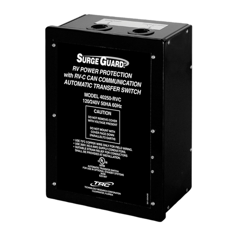
Model 40430 RVC
Automatic Transfer Switch
™
SURGE GUARD*
RV Power Protection
The 40430 series automatic transfer switch (ATS) has many different protective features
to protect your coach from low quality power. Included in these are protection against high
voltage, low voltage, and an incorrectly connected chassis ground. If one of these fault
conditions is encountered, the ATS will open both contactors in order to protect the coach.
Once the fault condition goes away, the ATS will delay for approximately 2.5 minutes before
trying to close the appropriate contactor again.
If the ATS fails to close the contactor or fails to transfer when expected, check the level of
the input voltage to ensure it is within the proper operating limits. Check if Open Ground
LED status is ON, indicating open ground. Also check that the ATS is correctly connected to
chassis ground and that the neutral conductor is correctly connected to ground at the power
pedestal. Wait 2.5 minutes to check if the fault condition was temporary and has cleared. If
so, the contactor will pull in at the end of the 2.5 minute period.
If available, check the 40430 display to see if an error message is displayed. The screen
will ash an error message for that failure such as “Loss of Ground”, “High Volt”, or “Reverse
Polarity”. The error condition must be corrected in order for the transfer switch to function
correctly. Refer to the table on the following page for help in troubleshooting these conditions.
The 40430 series also supports the optional wired Remote Display, part number 40299.
If there is no error message and the display instead reads “Delay Active” this means that the
fault condition has cleared and that the switch is going through a 2.5 minute delay before it will
attempt to close the contactor again. Wait until this delay is over to see if the ATS correctly
closes its contactor.
CAUTION: To avoid damage to the transfer switch or the RV, the torque specications on the terminal block cable installation diagram MUST be
followed. Make sure that the screws holding the input and output power cables down to the terminal block are fully tightened to the correct torque.
Failure to fully tighten these connections could cause an electrical shock or re hazard. Care must be taken to assure that the terminal screws are not
cross threaded, otherwise an improper torque will result.


