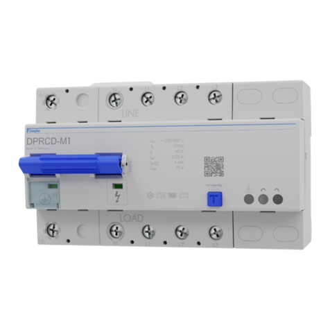
SOVAL 811-SS-OSY1SPDT Manual

Date:Apr. 7th, 2021
Rev. A
OPERATION&MAINTENANCEINSTRUCTION MANUAL
SUPERVISORYSWITCH FOROS&YGATE VALVE
1
GeneralDescription
ThisSupervisorySwitchisusedtomonitortheopenpositionofanOS&Y (outsidescrew and yoke)typegate
valve.Theseswitchesmount convenientlytomostOS&Y valvesranginginsizefrom2 to24 (50mm to
600mm).Thecoverisheldinplacebytwotamperresistant screwsthat requireaspecialtooltoremove.The
toolisfurnishedwitheachdevice.
Features
•All partshavecorrosionresistant finishes
•TwoConduitEntrances
•AdjustableLengthTripRod
•Three PositionSwitchDetectsTamperingand ValveClosure
•Fineadjustment featureforfast,easyinstallation
•OneortwoSPDT contact models(-1,-2,-3)
•UL Listedand FM Approved
TechnicalSpecifications
Testing
TheoperationoftheSupervisorySwitchand itsassociatedprotectivemonitoringsystemshallbeinspected,
tested,andmaintainedinaccordancewithall applicablelocaland nationalcodesand standardsand/orthe
AuthorityHavingJurisdiction(manufacturerrecommendsquarterlyormorefrequently).Aminimumtest
Model 811-SS-OSY1SPDT,811-SS-OSY2SPDT,811-SS-OSY3SPDT
Enclosure Cover: DieCast Finish: RedPowderCoat
Base: DieCast
All partshavecorrosionresistant finishes
CoverTamper
TamperResistant Screws
OptionalCoverTamperSwitchAvailable
3Amps/5 Ampsat 125/250VAC
Covertamperswitchwithtwoleadsand InsulatingPlate5KV
Contact
Ratings
811-SS-OSY1SPDT: OneSet ofSPDT
811-SS-OSY2SPDT: TwoSetsofSPDT
811-SS-OSY3SPDT: TwoSetsofSPDT andCoverTamperSwitch
10 Ampsat 125/250 VAC
2.5 Ampsat 30VDCResistive
Environmental
Limitations
-40°Cto60°COperatingTemperatureRange
IndoororOutdoorUse
IP67
Conduit EntrancesOneKnockoutsand oneholefor1/2 conduitprovided
ServiceUse NFPA13,13D,13R,72

Date:Apr. 7th, 2021
Rev. A
OPERATION&MAINTENANCEINSTRUCTION MANUAL
SUPERVISORYSWITCH FOROS&YGATE VALVE
2
shall consist ofturningthevalvewheeltowardstheclosedposition.TheSupervisorySwitchshall operate
withinthefirst tworevolutionsofthewheel. Fullyclosethevalveand ensurethattheSupervisorySwitch
doesnot restore.Fullyopenthevalveand ensurethattheSupervisorySwitchrestorestonormalonlywhen
thevalveisfullyopened.
Theory ofOperation
TheSupervisorySwitchisa3 positionswitch.Thecenterpositionisthenormalinstallationposition.Normal
iswhentheswitchisinstalledontheOS&Y valve,thevalveisfullyopenand thetriprodoftheSupervisory
Switchisinthegrooveofthevalvestem.Closingthevalvecausesthetriprodtorideup out ofthegroove
and activatestheswitches.RemovingtheSupervisorySwitchfromthevalvecausesthespringtopull thetrip
rodintheotherdirectionandactivatestheswitches.
Installation
No.1
a.WiththevalveintheFULL OPENposition,locatetheSupervisorySwitchacross thevalveyokeas far as
possiblefromthevalvegland sothatthespringloadedtriprodofit ispulledagainst thenon-threaded
portionofthevalvestem.PositiontheSupervisorySwitchwiththebracketnear thehandwheelas shownin
Fig. 6 ifpossibletoavoidcreatingapinchpoint betweenthewheeland theSupervisorySwitch.
b.Loosenthelockingscrew thatholdsthetriprodinplaceand adjusttherodlength.Whenadjusted
properly,therodshouldextend pastthevalvescrew,but notsofarthatit contactstheclampbar.Tighten
thelockingscrew to5in-lbsminimumtoholdthetriprodinplaceand properlysealtheenclosure.
NOTE: Iftriprodlengthisexcessive,loosenthelockingscrew and removethetriprodfromthetriplever.
Usingpliers,break off theone(1)inchlongnotchedsection.
Reinstall triprodand repeat Step3procedure.
c.MounttheSupervisorySwitchlooselywiththecarriagebolts
and clampbar supplied.Onvalveswithlimitedclearanceuse
J-hooks suppliedinsteadofthecarriageboltsand clampbar to
mount theSupervisorySwitch.

Date:Apr. 7th, 2021
Rev. A
OPERATION&MAINTENANCEINSTRUCTION MANUAL
SUPERVISORYSWITCH FOROS&YGATE VALVE
3
d.Deburr and smooththeedgesofthegroovetoprevent damagetothevalvepackingand toallowthetrip
rodtomoveeasilyinand out ofthegrooveas thevalveisoperated.
e.Finaladjustment canbemadebyslightlylooseningthetwoscrewsonthebracket and usingthefine
adjustment feature(see Fig. 5).Theadjustment iscorrect whentheplungers ontheswitchesaredepressed
bytheactuatorandthereisnocontinuitybetweentheCOM and NOterminalsontheswitches.
f.Tightentheadjustment screwsand all mountinghardwaresecurely(20 in-lbsminimum).Checktoinsure
that therodmovesoutofthegrooveeasilyand that theswitchesactivatewithintwoturnswhenthevalveis
operatedfromtheFULLOPENtowardstheCLOSEDposition.
g.Reinstallthecoverand tightenthecoverscrewsto15 in-lbsminimumtoproperlysealtheenclosure.
No.2
a.WiththevalveintheFULL OPENposition,locatetheSupervisorySwitchacross thevalveyokeas far from
thevalvegland as possiblesothatthespringloadedtriprodofit ispulledagainst thenon-threadedportion
ofthevalvestem.PositiontheSupervisorySwitchwiththebracketnear thehandwheel. Ifpossibletoavoid
creatingapinchpoint betweenthewheeland theSupervisorySwitch.
b.Mount theSupervisorySwitchlooselywiththecarriageboltsand clampbar supplied.
c. Loosenthelockingscrew thatholdsthetriprodinplaceand adjusttherodlength.Whenadjusted
properly,therodSupervisorySwitchshouldextend past thevalvescrew,butnotsofar thatit contactsthe
clampbar.Tightenthelockingscrew to5in-lbsminimumtoholdthetriprodinplaceand properlysealthe
enclosure.
d.Theremainingstepssuchas No.1.
No.3
Ifinstalledin14" andabove,Pleaseindicatespecialwhenbuy,we cancustomizeaccordingtotheactualsize
intheattachment.

Date:Apr. 7th, 2021
Rev. A
OPERATION&MAINTENANCEINSTRUCTION MANUAL
SUPERVISORYSWITCH FOROS&YGATE VALVE
4
StructuralDrawing
TypicalElectricalConnections(See Fig1)
Fig2
Fig1
Fig3
•WHENOS&YGATEVALVENORMALLYOPEN (See Fig2)When the
•WHENOS&YGATEVALVECLOSEORREMOVETHE
SUPERVISORYSWITCH(See Fig3)
COVERTAMPERSWITCHFig4
WHENREMOVETHECOVERCOMTO NC(See Fig4)
Covertamperswitch withthree leads.
This manual suits for next models
2
Table of contents

