manuals.online logo
Brands
  1. Home
  2. •
  3. Brands
  4. •
  5. EtherWAN
  6. •
  7. Switch
  8. •
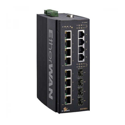
  9. EtherWAN EX73900X Series User manual

EtherWAN EX73900X Series User manual

Copyright 2021 EtherWAN Systems, Inc. Page 1
All Rights Reserved
EX73900X
04/09/2021
W70G-EX73900X1
1 Unpacking
Unpack the items. Your package should include:
➢One EX73900X hardened managed switch
➢One RJ-45 console cable
If items are missing or damaged, notify your
EtherWAN representative. Keep the carton and
packing material. The full product manual can be
downloaded from:
https://www.etherwan.com
2 What Else You Need
➢Appropriate cables for data ports. To prevent damage to the switch
from electrical surges, it is recommended to use STP (Shielded
twisted pair) cabling.
➢Personal computer or laptop
➢Appropriate SFP modules for SFP ports
3 Select a Location
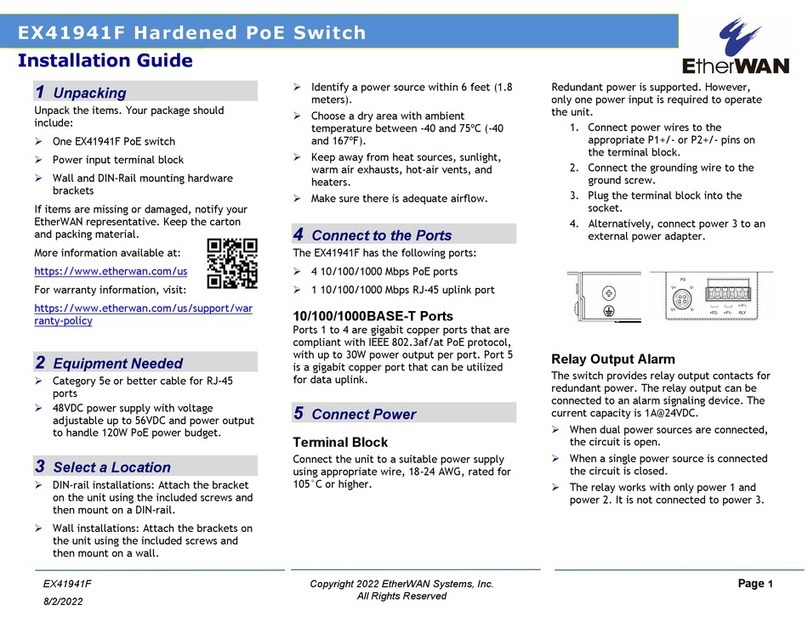
➢Installations: DIN-Rail mount.
➢Select a power source within 6 feet (1.8 meters).
➢Choose a dry area with ambient temperature between -40 and 75ºC (-
40 and 167ºF).
➢For use at altitudes up to 2000 meters, indoor use only.
➢Humidity range (Operational): 5% to 95%, non-condensation
➢For use in Pollution Degree 2 environment.
➢Do not block the device ventilation holes.
4 Connect to the Data Ports
Depending on the model, your switch can have the following ports:
EX73934X-0VB
12-port 10/100/1000BASE-T(X) + 4-port 1G/10G SFP+
EX73924X-0VB
8-port 10/100/1000BASE-T(X) + 4-port 1G/10G SFP+
EX73922X-0VB
8-port 10/100/1000BASE-T(X) + 2-port 1G/10G SFP+
10/100/1000BASE-TX Ports
To prevent damage to the switch from electrical surges, it is
recommended to use STP (Shielded twisted pair) cabling.
1G/10G SFP+ Ports
SFP+ transceivers can be installed directly into SFP+ slots. Ensure that
the same type of transceiver is used at both ends of the link and that the
correct type of fiber cable is used.
5 Apply Power
The switch has two pairs of power inputs.
Only one power input is required to operate the switch. However,
redundant power supply functionality is supported.
Power rating: 12-48VDC, Max. 2.13A.
The power input specification complies with the requirements of Safety
Extra Low Voltage (SELV), and the power supply should comply with UL
61010-1 and UL 61010-2-201
Terminal Block
The switch provides two power inputs on a terminal block with nominal
power of 24VDC. The terminal block has 5 terminal posts.
Pin
Description
Power 1
+
12-48VDC
−
Power Ground
Power 2
+
12-48VDC
-
Power Ground
Earth Terminal
Relay Output
Rating
0.6A @30VDC
Relay Output Alarm
The switch provides two relay output contacts. Both Relay 1 and Relay 2
signal actions from one of the digital inputs. The relay outputs can be
connected to an alarm signaling device. The Current is 0.6A@30VDC at
Normal Open or Normal Close.
Power-Up Sequence
When you apply power:
➢All Link/ACT LEDs blink momentarily.
➢The Power 1 LED goes ON.
➢LEDs for every port connected to a device flash, as the switch
conducts a brief Power On Self-Test (POST).
6 Front Panel LEDs
LED
Color
Status
Power 1 & 2
Green
On: Power on
Off: Power off
Link/Act
Green
On: Network connection established
Flashing: Port sending or receiving data
Alarm
Red
Link down or power down
EX73900X Series Hardened Managed Ethernet Switch
Installation Guide
EX73900X Hardened Managed Ethernet Switch
Copyright 2021 EtherWAN Systems, Inc. Page 2
All Rights Reserved
EX73900X
04/09/2021
W70G-EX73900X1
7 Digital IO-Setting
Connecting the Digital Inputs
The pin definitions for the digital input module are shown below. Each
digital input consists of two contacts on the 5-pin connector located on
the top of the switch. The inputs can be wired as either dry or wet
contacts.
Dry Contacts:
[DI1-/GND] [DI2-/GND]
Logic level 1: Close to GND(10mA)
Logic level 0: Open
Wet Contacts:
[DI1+/DI1-] [DI2+/DI2-]
Logic level 1 (High): 13~30 Volts (3.2mA)
Logic level 0 (Low): 0~3 Volts
Configuring Digital Input Alarms Using the Web Interface
Located under the Diagnostics group, the Digital IO-Setting page allows
for quick configuration and enabling of digital input and environmental
alarms.
To enable digital input alarms globally:
1. Choose Enable from the drop down menu in the Set State field.
2. Click on the Update Setting button to the right of the field.
To enable specific digital input alarms:
1. Enter a name or description of the alarm in the Description field.
2. In the Alert field, choose Enable/High from the drop-down menu if you
want the alarm to trigger in an occurrence of high voltage (wet contact),
or Open state (dry contact). Choose Enable/Low if you want the alarm to
trigger in an occurrence of low voltage (wet contact), or Closed to ground
state (dry contact).
3. Click on the Update Setting button at the bottom right to put the new
settings into effect. Then navigate to the Email configuration page.
8 Console Configuration
Connect to the switch console by connecting the RJ-45 console cable to
the console port of the switch and to the serial port of the computer
running a terminal emulation application (such as HyperTerminal or
Putty).
Configuration settings of the terminal-emulation program: Baud rate:
115,200bps, Data bits: 8, Parity: none, Stop bit: 1, Flow control: none.
The default login name is “root,” no password.
When logging into the GUI or the CLI for the first time, the switch will
prompt you to change the default password to a new one. The new
password must meet the following complexity requirements:
Minimum 8 characters and maximum 35 characters in password length
without leading or trailing blanks.
The password must contain characters from the following categories:
1. Uppercase English letters, (A to Z)
2. Lowercase English letters, (a to z)
3. Numbers, (0 to 9)
4. Non-alphanumeric characters (e.g. @, #, $), but not including (”, ?, !)
9 Web Configuration
Log in to the switch by launching a web browser and entering
192.168.1.10 in the address bar.
Enter the default login ID: root (no password) and click “Login.” The
system information screen will display.
10 USB Port
The switch is equipped with one USB port (Type A connector) for
configuration file and syslog backup. The USB port can be used to save
the configuration and Syslog to a (FAT32) USB storage device.
Plug the device into the USB port, and use the “Save Configuration”
command in the web interface, or “copy running-config startupconfig” in
the CLI. Use the “Export Logs to USB” command in the web interface, or
“export logs” in the CLI.
11 Other information
DIN-Rail Assembly Startup, and Dismantling
➢Assembly: Place the Switch on the DIN rail from above using the slot.
Push the front of the Switch toward the mounting surface until it
audibly snaps into place.
➢Startup: Connect the supply voltage to start up the Switch via the
terminal block.
➢Dismantling: Pull out the lower edge and then remove the Switch
from the DIN rail.
“The device can get hot to the touch after running at full load for
some time. Please use caution when handling the device.”
L'appareil peut devenir chaud au toucher après avoir fonctionné à pleine
charge pendant un certain temps. Soyez prudent lors de la manipulation
de l'appareil.
Power wiring information:
Use cable type - AWG (American Wire Gauge) 18-22 and corresponding
pin type cable terminals.
Using torque value 5 lb-in, do not use excessive force when fixing wiring.
The rating of the power wire used must be at least 105°C.
If the equipment is used in a manner not specified by the manufacturer,
the protection provided by the equipment may be impaired.
For repair or maintenance needs, contact EtherWAN directly.
Informations de câblage d'alimentation:
Utilisez le type de câble - AWG (American Wire Gauge) 18-22. valeur de
couple de 5 lb-in.
Le calibre du fil d'alimentation utilisé doit être d'au moins 105°C.
DESTINÉ À ÊTRE UTILISÉ AVEC DES CONDUCTEURS EN CUIVRE SEULEMENT.
Si la méthode d'utilisation de l'équipement diffère de celle décrite par le
fabricant, la protection assurée par l'équipement risque d'être altérée.
Contactez-nous pour l'entretien ou la reparation.
Label clean up:
It must be wiped with a dry cloth to clean up the labelling.
If the equipment is used in a manner not specified by the manufacturer,
the protection provided by the equipment may be impaired.
The product is open type, intended to be installed in an industrial control
panel or an enclosure.
SFP module specification requirement: Class 1 laser product. Complies
with CDRH 21CFR 1040.10 and 1040.11. Rated 3.3 or 5 VDC.
The installation safety of any system incorporating the equipment is the
responsibility of the assembler of the system.
Nettoyage de l’étiquette:
Nettoyez avec un chiffon doux et sec.
Si l’équipement est utilisé d’une façon non conforme aux directives du
manufacturier, il peut être endommagé.
Le produit est du type ouvert et doit être installé dans un coffret ou
panneau de contrôles industriel.
Spécification pour le module SFP : Laser classe 1 conforme aux normes
CDRH 21CFR 1040.11 Alimentation 3.3 ou 5 VCC.
La sécurité d’une l’installation d’un système incorporant l’équipement
est la responsabilité de l’assembleur du système.
Manufacturer information:
ETHERWAN SYSTEMS, INC.
33F, No. 93, Sec. 1, Xintai 5th Rd., Xizhi Dist., New Taipei City, 221
Taiwan
Other EtherWAN Switch manuals

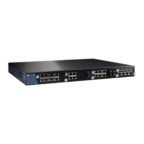
EtherWAN EX78162 Series User manual

EtherWAN

EtherWAN EX78162 Series User manual

EtherWAN EX26262F Series User manual

EtherWAN

EtherWAN EX26262F Series User manual

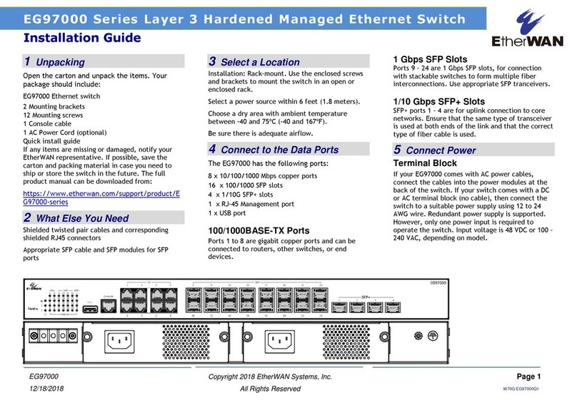
EtherWAN EG97000 Series User manual

EtherWAN

EtherWAN EG97000 Series User manual

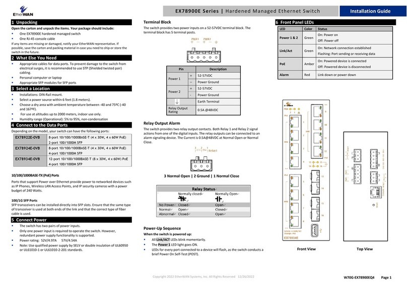
EtherWAN EX78900E Series User manual

EtherWAN

EtherWAN EX78900E Series User manual

EtherWAN EX73900 Series User manual

EtherWAN

EtherWAN EX73900 Series User manual

EtherWAN EX87000 Series User manual

EtherWAN

EtherWAN EX87000 Series User manual

EtherWAN EX42008 Series User manual

EtherWAN

EtherWAN EX42008 Series User manual

EtherWAN EX25611 User manual

EtherWAN

EtherWAN EX25611 User manual

EtherWAN InfraGreEn IG5 User manual
EtherWAN

EtherWAN InfraGreEn IG5 User manual

EtherWAN ER59000 Series User manual

EtherWAN

EtherWAN ER59000 Series User manual

EtherWAN EX17242 User manual

EtherWAN

EtherWAN EX17242 User manual

EtherWAN EX27000 Series User manual

EtherWAN

EtherWAN EX27000 Series User manual

EtherWAN EX42000 Series User manual

EtherWAN

EtherWAN EX42000 Series User manual

EtherWAN EX17242 User manual

EtherWAN

EtherWAN EX17242 User manual

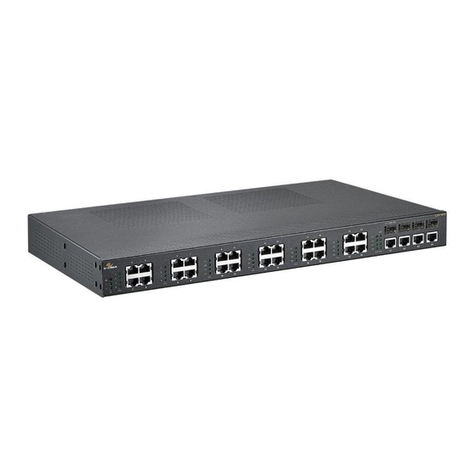
EtherWAN EX73000 Series User manual

EtherWAN

EtherWAN EX73000 Series User manual

EtherWAN OttoE TG103 Series User manual

EtherWAN

EtherWAN OttoE TG103 Series User manual

EtherWAN OttoE TF100 Sereis User manual

EtherWAN

EtherWAN OttoE TF100 Sereis User manual

EtherWAN EX87000 Series User manual

EtherWAN

EtherWAN EX87000 Series User manual

EtherWAN EX95000 Series User manual

EtherWAN

EtherWAN EX95000 Series User manual

EtherWAN EX89000 User manual

EtherWAN

EtherWAN EX89000 User manual

EtherWAN EX77000 Series User manual

EtherWAN

EtherWAN EX77000 Series User manual

EtherWAN EX32905 Series User manual

EtherWAN

EtherWAN EX32905 Series User manual

EtherWAN EX42395AT User manual

EtherWAN

EtherWAN EX42395AT User manual

EtherWAN EX41941F User manual

EtherWAN

EtherWAN EX41941F User manual

Popular Switch manuals by other brands

THOMSON Grass Valley Triton TTN-BDS-6464 installation manual

THOMSON

THOMSON Grass Valley Triton TTN-BDS-6464 installation manual

D-Link DU-H7 user manual

D-Link

D-Link DU-H7 user manual

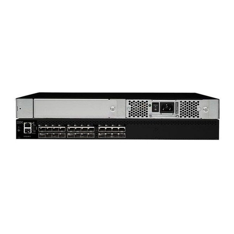
IBM RedBooks SAN24B-5 Installation, service and user guide

IBM

IBM RedBooks SAN24B-5 Installation, service and user guide

BERNSTEIN SHS3 Series Installation and operating instructions

BERNSTEIN

BERNSTEIN SHS3 Series Installation and operating instructions

3Com SWITCH 4050 Quick reference guide

3Com

3Com SWITCH 4050 Quick reference guide

TRENDnet TK-IP101 user guide

TRENDnet

TRENDnet TK-IP101 user guide

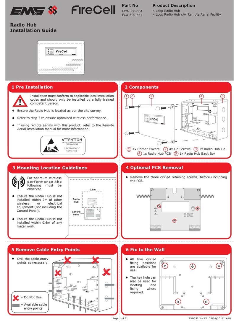
EMS FireCell FCX-500-444 installation guide

EMS

EMS FireCell FCX-500-444 installation guide

EUCHNER STA4A-2131A024L024RC18 operating instructions

EUCHNER

EUCHNER STA4A-2131A024L024RC18 operating instructions

TP-Link TL-SG105 installation guide

TP-Link

TP-Link TL-SG105 installation guide

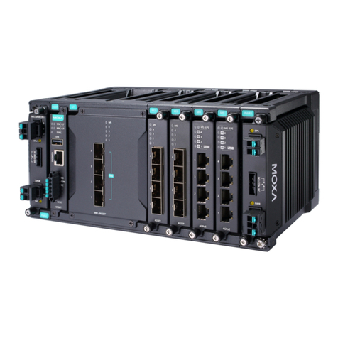
Moxa Technologies MDS-G4000-4XGS Series Quick installation guide

Moxa Technologies

Moxa Technologies MDS-G4000-4XGS Series Quick installation guide

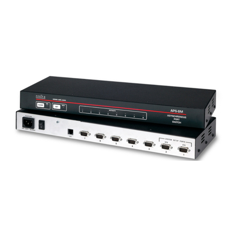
WTI APS-8M user guide

WTI

WTI APS-8M user guide

UPOWER A03-ATS16A user manual

UPOWER

UPOWER A03-ATS16A user manual

ADC CUDA 3 Administration guide

ADC

ADC CUDA 3 Administration guide

LevelOne FSW-0507TX datasheet

LevelOne

LevelOne FSW-0507TX datasheet

Leonton ET2-0500 Series user manual

Leonton

Leonton ET2-0500 Series user manual

Avocent SWITCHVIEW OSD - Installation & user guide

Avocent

Avocent SWITCHVIEW OSD - Installation & user guide

SMC Networks ZSE10F Series Operation manual

SMC Networks

SMC Networks ZSE10F Series Operation manual

PTN SCU21T-KVM user manual

PTN

PTN SCU21T-KVM user manual

manuals.online logo
manuals.online logoBrands
  • About & Mission
  • Contact us
  • Privacy Policy
  • Terms and Conditions

Copyright 2025 Manuals.Online. All Rights Reserved.