Sovereign YT9757 User manual


2
CONTENTS
CONTENTS 2
GENERAL SAFETY WARNINGS 3
WARNING SYMBOLS 9
IN THE BOX 10
OPERATION 11
MAINTENANCE AND STORAGE 19
TECHNICAL DATA 20
RECYCLING AND DISPOSAL 22
UK PLUG 22
GETTING HELP 23
WARRANTY 24

3
GENERAL SAFETY WARNINGS
WARNING! Read all safety warnings,
instructions, illustrations and specifications
provided with this power tool. Failure to
follow all instructions listed below may result
in electric shock, fire and/or serious injury.
Save all warnings and instructions for
future reference. The term "power tool" in
the warnings refers to your mains-operated
(corded) power tool or battery-operated
(cordless) power tool.
1) Work area safety
a) Keep work area clean and well lit. Cluttered or
dark areas invite accidents.
b) Do not operate power tools in explosive
atmospheres, such as in the presence of
flammable liquids, gases or dust. Power tools
create sparks which may ignite the dust or fumes.
c) Keep children and bystanders away while
operating a power tool. Distractions can cause
you to lose control.
2) Electrical safety
a) Power tool plugs must match the outlet. Never
modify the plug in any way. Do not use any
adaptor plugs with earthed (grounded) power
tools. Unmodified plugs and matching outlets will
reduce risk of electric shock.
b) Avoid body contact with earthed or grounded

4
surfaces, such as pipes, radiators, ranges and
refrigerators. There is an increased risk of electric
shock if your body is earthed or grounded.
c) Do not expose power tools to rain or wet
conditions. Water entering a power tool will
increase the risk of electric shock.
d) Do not abuse the cord. Never use the cord
for carrying, pulling or unplugging the power
tool. Keep cord away from heat, oil, sharp edges
or moving parts. Damaged or entangled cords
increase the risk of electric shock.
e) When operating a power tool outdoors, use an
extension cord suitable for outdoor use. Use of
a cord suitable for outdoor use reduces the risk of
electric shock.
f) If operating a power tool in a damp location
is unavoidable, use a residual current device
(RCD) protected supply. Use of an RCD reduces
the risk of electric shock.
3) Personal safety
a) Stay alert, watch what you are doing and
use common sense when operating a power
tool. Do not use a power tool while you are
tired or under the influence of drugs, alcohol
or medication. A moment of inattention while
operating power tools may result in serious
personal injury.
b) Use personal protective equipment. Always
wear eye protection. Protective equipment such

5
as a dust mask, non-skid safety shoes, hard hat, or
hearing protection used for appropriate conditions
will reduce personal injuries.
c) Prevent unintentional starting. Ensure the
switch is in the off-position before connecting
to power source and/or battery pack, picking
up or carrying the tool. Carrying power tools
with your finger on the switch or energising power
tools that have the switch on invites accidents.
d) Remove any adjusting key or wrench before
turning the power tool on. A wrench or a key left
attached to a rotating part of the power tool may
result in personal injury.
e) Do not overreach. Keep proper footing and
balance at all times. This enables better control
of the power tool in unexpected situations.
f) Dress properly. Do not wear loose clothing or
jewellery. Keep your hair, clothing and gloves
away from moving parts. Loose clothes, jewellery
or long hair can be caught in moving parts.
g) If devices are provided for the connection of
dust extraction and collection facilities, ensure
these are connected and properly used. Use of
these devices can reduce dust-related hazards.
h) Do not let familiarity gained from frequent use
of tools allow you to become complacent and
ignore tool safety principles. A careless action
can cause severe injury within a fraction of a
second.

6
4) Power tool use and care
a) Do not force the power tool. Use the correct
power tool for your application. The correct
power tool will do the job better and safer at the
rate for which it was designed.
b) Do not use the power tool if the switch does
not turn it on and off. Any power tool that cannot
be controlled with the switch is dangerous and
must be repaired.
c) Disconnect the plug from the power source
and/or the battery pack from the power tool
before making any adjustments, changing
accessories, or storing power tools. Such
preventive safety measures reduce the risk of
starting the power tool accidentally.
d) Store idle power tools out of the reach of
children and do not allow persons unfamiliar
with the power tool or these instructions
to operate the power tool. Power tools are
dangerous in the hands of untrained users.
e) Maintain power tools. Check for misalignment
or binding of moving parts, breakage of parts
and any other condition that may affect the
power tools operation. If damaged, have the
power tool repaired before use. Many accidents
are caused by poorly maintained power tools.
f) Keep cutting tools sharp and clean. Properly
maintained cutting tools with sharp cutting edges
are less likely to bind and are easier to control.
g) Use the power tool, accessories and tool bits,

7
etc., in accordance with these instructions,
taking into account the working conditions and
the work to be performed. Use of the power tool
for operations different from those intended could
result in a hazardous situation.
h) Keep handles and gripping surfaces dry, clean
and free from oil and grease. Slippery handles
and gripping surfaces do not allow for safe
handling and control of the tool in unexpected
situations.
Service
a) Have your power tool serviced by a qualified
repair person using only identical replacement
parts. This will ensure that the safety of the power
tool is maintained.

8
Planer safety warnings
1. Wait for the cutter to stop before setting
the tool down. An exposed rotating cutter may
engage the surface leading to possible loss of
control and serious injury.
2. Hold the power tool by insulated gripping
surfaces only, because the cutter may contact
its own cord. Cutting a “live” wire may make
exposed metal parts of the power tool “live” and
could give the operator an electric shock.
3. Use clamps or another practical way to
secure and support the workpiece to a stable
platform. Holding the workpiece by your hand or
against the body leaves it unstable and may lead
to loss of control.

9
WARNING SYMBOLS
Warning!
Read the instructions
Wear ear protection
Wear eye protection
Wear a dust mask
Class II tool
The product complies with the applicable
European directives, and an evaluation method
of conformity for these directives was done.
Recycle unwanted materials instead of
disposing of them as household waste. All tools,
hoses and packaging should be sorted, taken to
the local recycling centre and disposed of in an
environmentally safe way.
The product complies with the applicable UK
directives, and an evaluation method of conformity
for these directives was followed.
10
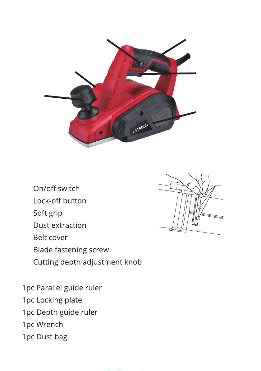
IN THE BOX
Description
1.
2.
3.
4.
5.
6.
7.
Accessories
6
7
4
23
1
5

11
OPERATION
NOTE: Before using the tool, read the instruction book
carefully.
INTENDED USE
The tool is intended for planing of firmly supported wooden
materials, such as beams and boards. It is also suitable for
bevelling edges and rebating.
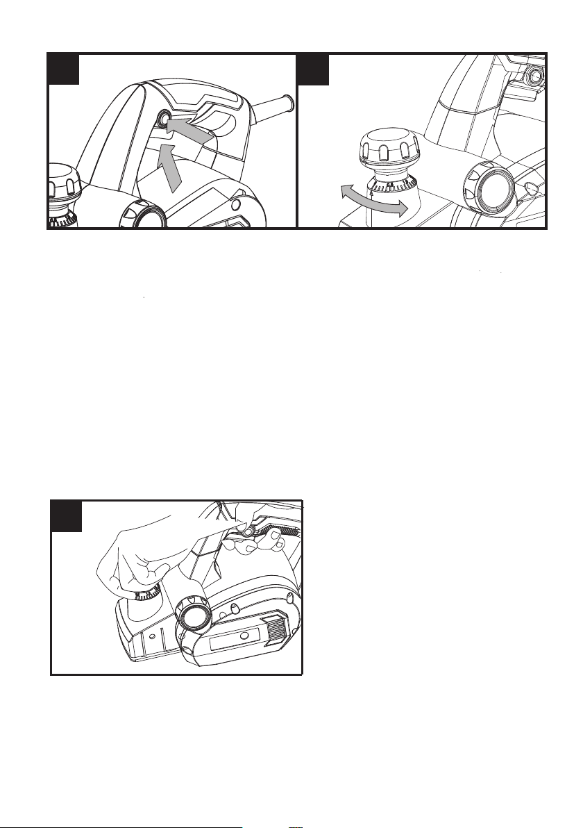
1. SAFETY ON/OFF SWITCH (SEE FIG. A)
The switch is locked off to prevent accidental starting. Depress
the lock-off button then the on/off switch and release the lock-
off button. To switch off, just release the on/off switch.
WARNING! Danger of kickback! Apply the tool to the
work piece only when switched on.
2. CUTTING DEPTH ADJUSTMENT (SEE FIG. B)
The planing depth can be adjusted from 0 to 2mm. Rotate
the cutting depth adjustment knob to set the required cutting
depth with the scale. Clockwise rotation increases the planing
depth; anticlockwise rotation reduces the planing depth.
It is recommended that test cuts be made in scrap wood after
each adjustment to make sure that the desired amount of
wood is being removed by your planer.
NOTE: To protect blades during storage, transporting, etc., set
the blade depth adjustment knob to 0.
12
3. STANDARD SURFACE PLANING (SEE FIG. C)
Set the desired cutting depth. Position the front part of the
base plate flat onto the work surface. Make sure that the
blades are not touching the workpiece. Switch the tool on
and push your planer forward and it will start cutting. Always
maintain all of the base plate flat on the work surface to
prevent the cutting blade jumping. Move the plane evenly over
the work surface.
Be careful to avoid hitting nails during operation. It could nick,
crack, or damage blades. We suggest that you always keep an
extra set of blades on hand for replacement.
AB
C

13
4. EDGE CHAMFERING (SEE FIG. D, E)
CAUTION: Always use both hands on the tool for any
operation. It assures you maintain control and avoids
the risk of serious personal injury. The workpiece must
always be properly supported and clamped so that
both hands will be free to control the planer.
Using the V-groove in the base plate, you can make a chamfer
on the workpiece edge. Guide the planer along the edge and
maintain a constant angle and force to produce a good finish.
You can control the angle of the chamfer with your hands.
Make a test chamfer on a scrap piece of wood. Maintain
downward pressure to keep your planer flat at the beginning
and the end of the work surface.
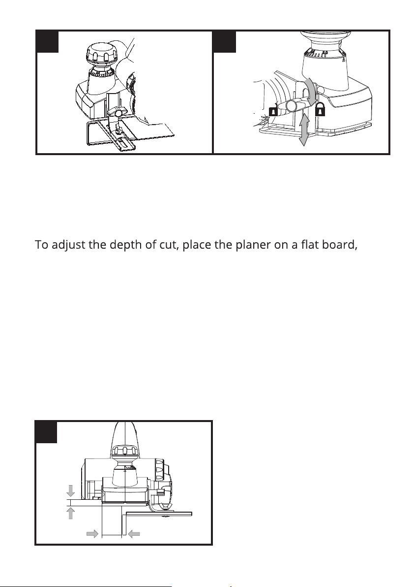
5. USING THE PARALLEL GUIDE (SEE FIG. F)
Insert the screw provided through the hole on the support of
parallel guide (7). Turn the screw into the nut on the housing.
Fix the parallel guide on the support of parallel guide with the
screw and nut. Ensure the screws are tightened securely.
NOTE: The parallel guide should be fitted on the left of
housing.
To adjust the required width of cut, loosen the nut and slide
the parallel guide to the required position. Retighten the nut
fully. Use the parallel guide while cutting. The guide should be
held firmly against the edge of the workpiece.
D
45o
E
14
6. USING THE REBATE (SEE FIG. G)
Insert the screw provided through the slot on the Rebate.Turn
the screw into the nut on the housing.
The cut depth adjustment can be set from 0 to 10mm.
then loosen the screw and slide the cut depth adjustment
guide up and down for required depth. Tighten the thumb
screw fully.
7. REBATING (SEE FIG. H)
The width of rebating cut (a) is adjustable by moving the
parallel guide. The depth of rebating cut (b) is determined by
moving the rebate, and the number of passes made along the
workpiece. Make sure that the plane is guided with a lateral
supporting pressure.
F G
H
b
a

15
8. USING THE DUST BAG
Your planer is equipped with a dust bag for collection of wood
chips in the work area. Make sure the zipper on the bag is fully
closed. To fit the dust bag, simply insert the tube end of the
bag into the dust extraction outlet.
Then switch on and start planing.
CLEANING DUST EXHAUST OUTLET & EMPTYING
THE DUST BAG
After using your planer for an extended period of time or
when planing wet greentimber, chips may build-up in the dust
exhaust outlet and require clearing. Chip build-up restricts air
flow and causes the motor to overheat. Turn off the planer
and remove the dust bag from the dust exhaust outlet. Clean
the chip and dust exhaust outlet of your planer with a small
piece of wood. Do not use your hands or fingers. Unzip the
dust bag and empty all chips from it. Ensure the collar is free
from debris.
We recommend emptying the dust bag every 3-6 minutes.
9. BLADE FITTING AND CHANGING (SEE FIG. I, J, K, L)
WARNING! Remove the power cord from the socket
before carrying out any adjustments or changing
blades. Always put on gloves when replacing blades.
NOTE: Dull and worn blades cannot be reground and must be
replaced. Always replace blades in pairs.
Using the blades spanner provided, loosen the three
installation screws approximately 1/2 rotation anticlockwise.
NOTE: Do not over-loosen the screws. If the screws are too
loose, the alignment of the new blade will not be accurate.
Before removing the old blades, take notice of the direction
of cut as well as how the tapered edge of the old blade is
oriented. The tapered edge of the new blade must be in the
same orientation as the original blade.

16
Press the safety cover down with your finger. Push the blade
out with the tip of a spanner (or a screwdriver) and then
remove.
NOTE:There is no needto remove the blade clamp, as this will
change the factory settings for cutting blade height control.
NOTE: If a blade cannot be pushed out easily after loosening
the screws, use a piece of wood to pry the blade loose from
the blade clamp, with a short sharp blow. Then push with a
screwdriver to remove the blade. If necessary, tap the piece of
wood sharply with a small hammer to break the blade loose.
Before reinserting a new or reverse blade, always clean both
the blade and the blade seat if dirty. Slide the blade into
the clamp with a spanner (or a screwdriver) in the correct
orientation.Check the blade is equal with the clamp.Retighten
the three blade screws with the spanner.
K
I J
L

17
Repeat the above procedure to change the other blade.
After the blades are replaced, check if the blades are parallel
and aligned to the rear base plate with a ruler. If not, you
can adjust the blades with the hexagonal wrench provided.
Firstly, loosen the three screws on the blade clamp. Turn the
socket head screw clockwise, the blade will be risen. Turn it
anticlockwise, the blade will be lowered down.
Finally retighten the three screws fully.
10. REPLACING A DRIVE BELT (SEE FIG. M, N)
WARNING!
1. Remove the plug from the socket before carrying out any
adjustment, servicing or maintenance.
2. The cutting blades will be turning and may cause injury.
Loosen the screws and remove the belt cover. Remove the
worn drive belt from the large pulley and the pinion and clean
them. Lace the new belt on the top of the pinion and turn it
manually, press it on the large pulley. Make sure that the drive
belt runs exactly along the length of the grooves of the pinion
and the pulley. Replace the belt cover. Install the cover screw
and tighten fully.
N
M

18
11. CORRECT PLANER BLADE SETTING (SEE FIG. O)
Your planing surface will end up rough and uneven, unless the
blade is set properly and securely.
The blade must be mounted so that the cutting edge is
absolutely level, that is, parallel to the surface of the rear base.
FIG. P shows some examples of proper and improper settings.
(A) Front base (moveable shoe)
(B) Rear base (stationary shoe)
1) Correct setting
Although this side view cannot show it, the edges of the blade
run perfectly parallel to the rear base surface.
2) Nicks in surface
Cause: one or both blades fail to have edge parallel to rear
base line.
3) Gouging at start
Cause: one or both blade edges fail to protrude enough in
relation to rear base line.
4) Gouging at end
Cause: one or both blade edges protrude too far in relation to
rear base line.
P
O

19
MAINTENANCE AND STORAGE
IMPORTANT:
Make sure that the tool has been thoroughly cleaned
before storing it in a clean, dry and safe place, out of
the reach of children.
1. Switch the product 'OFF' and disconnect it from the power
supply before transporting it anywhere.
2. Always carry the product on its gripping surfaces.
3. Protect the product from any heavy impact or strong
vibrations which may occur during transportation in
vehicles.
4. Secure the product to prevent it from slipping or falling
over.

20
TECHNICAL DATA
Model YT9757
Voltage/power 220-240V~ 50Hz/710W
No-load speed 16500/min
Max. cutting width 82mm
Max. cutting depth 2mm
Max. rebating depth 10mm
Protection class / II
Weight 2.8kg
NOISE AND VIBRATION DATA
A weighted sound pressure (LpA) 83.1dB(A), k=3dB(A)
A weighted sound power (LwA) 94.1dB(A), k=3dB(A)
Vibrations 6.96 m/s² K=1.5 m/s²
The sound intensity level for the operator may exceed 80
dB(A) and ear protection measures are necessary.
The declared vibration value has been measured in
accordance with a standard test method (according to EN
62841) and may be used for comparing one product with
another. The declared vibration value may also be used in a
preliminary assessment of exposure.
WARNING!
The vibration emission value during actual use of
depending on the ways in which the tool is used and
dependant on the following examples and other
variations on how the tool is used:
How the tool is used and the materials being cut or
drilled.
The tool being in good condition and well maintained.
Using the correct accessory for the tool and ensuring it
is sharp and in good condition.
The tightness of the grip on the handles and if any
anti-vibration accessories are used.
This manual suits for next models
1
Table of contents


