DRIVE CHAINS FIG. 17 furnished
as
replacements,
are complete with connecting
links.
1.
Drain
oil
from gear box and remove
gear
box
cast-
ing.
Disconnect
link,
install
new
chain
around
sprockets
and
connect
link.
SHIFTER
FIG. 13. Drain
oil
and remove
cover.
Loose
n
shifter
for k
screw,
screw
in
gear
box which
holds large
collar,
and remove
shifter
assembly.
the
slinger
disc
will
have to be bent toward
the
gear. Use amallet
or
block
of
wood and
tap the
disc
around
the
circumference
until
the proper
clearance
is
obtained.
4.
When
functioning properly,
the
slinger
carries
the
oil
up
to the cutterhead
worm
and intermediate
gear.
5.
Replace
sprockets,
chains,
gear box and cover.
6.
Fill
with
oil.
SEE LUBRICATION.
Figure
18
~LOCKPLATE
\.~
SCREW
5.
Remove
retainer
ring and
thrust
bearing.
6.
Install
new gear. NOTE: Complete
assembly
is
available
as
a
replacement,
see
parts
list.
2. Remove
chains
and
sprockets.
3. Remove both
screws
in
lockplateS,
Fig.
18.
4. Remove both gear
assemblies
Fig.
19.
1. Remove gear box.
Figure
17
INTERMEDIATE GEAR, FIG.
·18,19,20.
Remove
shifter
as
previously
described.
A
.~.:J~~
Figure
19
6
2. Remove
slinger
using an arbor
press
or
similar
equipment. NOTE: COMPLETE ASSEMBLY
IS
AVAILABLE
AS
REPLACEMENT,
SEE
PARTS
LIST.
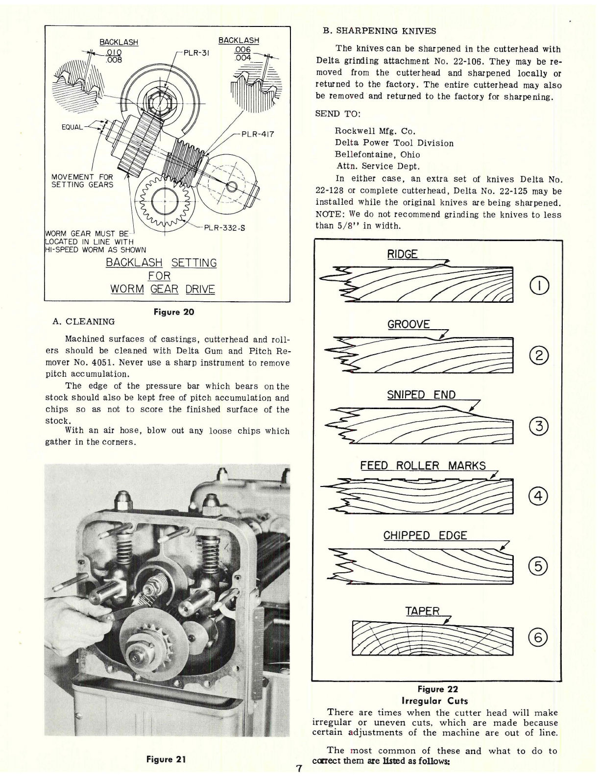
3. After gear
assemblies
are
instaHed
in
planer and
adjusted
for
correct
backlash
(Fig.
18),
the oil
slinger
disc
should be
checked
for
clearance,
(Fig.
21).
Use afeeler gauge
.010"
to
measure
the
clearance
between
the
slinger
and the inter-
mediate
gear.
If
the
clearance
is
more than
.010",
7.
Check
cutter
head worm.
It
is
advisable
to
replace
this
part when replacing the
intermediate
gear.
8.
Replace
the two gear
assemblies.'
INTERMEDIATE
GEAR
NOTE:
BEFORE
TIGHTENING
LOCKPLATE
C~~t:f':~~"ii~~
SCREWS,
MAKE
SUR.E
THE
BACKLASH
IS
EQUALIZED, SEE FIG.
20~
CLUTCH SPROCKET GEAR
AND
SLINGER FIGS.
18. 19, 20.
To
remove.
it
is
necessary
to
first
remove
the
oil
slinger
disc.
1. Remove
retainer
ring, bearing and
sprocket.