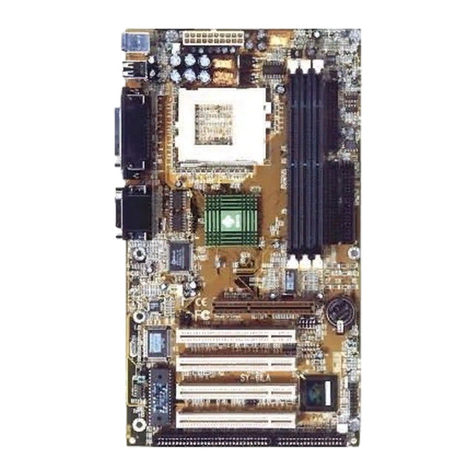
SOYO SY-6BA+III User manual

SY-6BA+III
Motherboard
Quick Start Guide
FC
CTested To Comply
With FCC Standards
FOR HOME OR OFFICE USE
POST CONSUMER
RECYCLED PAPER
100%
Hardware
Installation
Quick BIOS
Setup
Introduction
The SOYO CD

SOYO™
2
SY-6BA+III Motherboard
Pentium
®
III, Pentium
®
II & Celeron
TM
processors
82440 BX AGP/PCI Motherboard
66&100MHz Front Side Bus supported
ATX Form Factor
Copyright © 1999 bySoyo Computer Inc.
Trademarks:
Soyo is a registered trademark of Soyo Computer Inc. All trademarks are the property of their
owners.
Product Rights:
Product and corporate names mentioned in this publication are used for identification purposes
only and may be registered trademarks or copyrights of their respective companies.
Copyright Notice:
All rights reserved. This manual is copyrighted by Soyo Computer Inc. You may not reproduce,
transmit, transcribe, store in a retrieval system, or translate into any language, in any form or by
any means, electronic, mechanical, magnetic, optical, chemical, manual or otherwise, any part of
this publication without express written permission of Soyo Computer Inc.
Disclaimer:
Soyo Computer Inc. makes no representations or warranties regarding the contents of this
manual. We reserve the right to revise the manual or make changes in the specifications of the
product described within it at any time without notice and without obligation to notify any
person of such revision or change. The information contained in this manual is provided for
general use by our customers. Our customers should be aware that the personal computer field is
the subject of many patents. Our customers should ensure that their use of our products does not
infringe upon any patents. It is the policy of Soyo Computer Inc. to respect the valid patent rights
of third parties and not to infringe upon or assist others to infringe upon such rights.
Restricted Rights Legend:
Use, duplication, or disclosure by the Government is subject to restrictions set forth in
subparagraph (c)(1)(ii) of the Rights in Technical Data and Computer Software clause at
252.277-7013.
About This Guide:
This Quick Start Guide is for assisting system manufacturers and end users in setting up and
installing the Motherboard. Information in this guide has been carefully checked for reliability;
however, no guarantee is given as to the correctness of the contents. The information in this
document is subject to change without notice.
If you need any further information, please visit our Web Site on the Internet. The address is
"http://www.soyo.com.tw".
6BA+III Serial - Version 1.3 - Edition: December 1999
*Thesespecificationsaresubjecttochangewithoutnotice
SY-6BA+III
Quick Start Guide
3
Introduction
1
1
Introduction
Congratulationsonyourpurchaseofthe
SY-6BA+III
Motherboard.ThisQuickStartGuide
describesthestepsforinstallingandsettingupyournewMotherboard.
ThisguideisdesignedforalluserstoprovidethebasicstepsofMotherboardsettingand
operation.Forfurtherinformation, pleasereferto SY-6BA+IIIMotherboardUser'sGuideand
TechnicalReferenceonlinemanualincludedontheCD-ROMpackedwithyour
Motherboard.
Unpacking
WhenunpackingtheMotherboard,checkforthefollowingitems:
u
TheSY-6BA+III82440BXAGP/PCIMotherboard
u
ThisQuickStartGuide
u
TheInstallation CD-ROM
u
SOYO3-in-1BonusPackCD-ROM(Norton AntiVirus,
GhostandVirtualDrive)
u
TheCPURetentionSet
u
OneIDEDeviceFlatCable
u
OneFloppyDiskDriveFlatCable

SY-6BA+III Quick Start Guide
4
Introduction
SY-6BA+III Motherboard Layout
Key Features
Ø
SupportsIntelPentium
®
IIIprocessor(450-
600MHz), Pentium
®
IIprocessor(233-450MHz)&
Celeron
TM
processor(266-433MHz
)
Ø
JumperlessandCPUvoltageAdjustable
Ø
PC98,ACPI,UltraDMA/33
Ø
Power-onbymodemoralarm
Ø
SOYOCOMBOSetup
Ø
SupportsWake-On-LAN (WOL)
Ø
Supportsonboardhardwaremonitoringand
includesHardware Doctor™utility
Ø
SupportsCreativeSB-LINK™for PCI audio
card
Ø
1x32-bitAGPslot
Ø
5x32-bitbusmasterPCIslots
Ø
2xUSBportsonboard
Ø
1xIrDAport
Ø
Supportsmultiple-bootfunction
Ø
Y2KCompliant
Ø
SupportsPowerFailureResume
COM 1
COM 2
PRT
USB 1USB 2
PS/2 KB
Connector
PS/2 Mouse
Connector
JP10
PCI Slot #1
PCI Slot #2
PCI Slot #3
PCI Slot #4
PCI Slot #5
ISA Slot #1
ISA Slot #2
JP5
JP1
JP8 LED1
3V
Lithium
Battery
JP44
®
SB-LINK
(PC PCI)
®
IR1
1
5
1
1
CPUFAN
PWRFAN
ITE 8671
I/O Chipset
CHAFAN
1
IDE 1
IDE 2
1
1
1
1
FDC
®
1
3
AGP Slot
ATX
Power
Speaker
Keylock
Power
LED
Reset
PWRBT
Turbo
LED
HDD LED
_
+
_
+
_
+
_
+
3
1
Flash BIOS
1
3
TM
Slot 1
Intel
82371 EB
DIMM 1
DIMM 2
DIMM 3
DIMM 4
8 2 8 A C
Hardware
Monitoring
Winbond
W83782M
Intel
82443 BX

SY-6BA+III
Quick Start Guide
5
Hardware
Installation
2
2
Installation
ToavoiddamagetoyourMotherboard,followthesesimpleruleswhilehandling
thisequipment:
l
BeforehandlingtheMotherboard,groundyourselfbygraspinganunpaintedportion
ofthesystem'smetalchassis.
l
RemovetheMotherboardfromitsanti-staticpackaging.Holditbytheedgesand
avoidtouchingitscomponents.
l
ChecktheMotherboardfordamage.Ifanychipappearsloose,presscarefullytoseat
itfirmlyinitssocket.
Followthedirectionsinthissectiondesignedtoguideyouthroughaquickandcorrect
installationofyournew
SY-6BA+III
Motherboard.For detailedinformation,pleasereferto
SY-6BA+IIIMotherboardUser'sguideandTechnical Reference onlinemanualincludedon
theCD-ROMpackedwithyourMotherboard.
PREPARATIONS
Gatherandprepareallthenecessaryhardwareequipmenttocompletetheinstallation
successfully:
u
Slot1processorwithbuilt-inCPUcoolingfan(boxedtype)
u
SDRAMmodule
u
Computercaseandchassiswithadequatepowersupplyunit
u
Monitor
u
PS/2Keyboard
u
PointingDevice(PS/2mouse)
u
VGACard
u
SoundCard(optional)
u
Speaker(s)(optional)
u
DiskDrives: HDD,CD-ROM, Floppydrive…
u
ExternalPeripherals:Printer,Plotter,andModem-(optional)
u
InternalPeripherals:ModemandLANcards(optional)

SY-6BA+III Quick Start Guide
6
Hardware
Installation
Install the Motherboard
Followthestepsbelowinordertoperformtheinstallationofyournew
SY-6BA+III
Motherboard.
Step 1. Install the CPU
Mark your CPU Frequency:
RecordtheworkingfrequencyofyourCPU
thatshouldbeclearlymarkedontheCPUcover.
FSB66MHz
266MHz(66 x4.0) 333MHz (66 x5.0) 400MHz(66 x6.0)
300MHz(66 x4.5) 366MHz (66 x5.5) 433MHz(66 x6.5)
FSB100MHz
350MHz(100 x 3.5) 450MHz (100 x4.5) 550MHz (100 x5.5)
400MHz(100 x4.0) 500MHz (100 x5.0) 600MHz(100 x6.0)
CPU Mount Procedure:
Tomounttheprocessorthatyouhavepurchased
separately,followtheseinstructions.
Retention Module Step 1. Open the two sides by folding them up.
Step 2. Insert the CPU into the retention
module. The CPU fits in the CPU
slot in only ONE way, do not try to
force it in.
Step 3. After completely inserting the CPU,
Now your CPU is ready for use.
Note:Installing a heatsink andcooling fan ontop of yourCPU isnecessary for properheat dissipation. Failingto
installthese items mayresult in overheatingand possibleburn-outof yourCPU

SY-6BA+III
Quick Start Guide
7
Hardware
Installation
Step 2. Make Connections to the Motherboard
ThissectiontellshowtoconnectinternalperipheralsandpowersupplytotheMotherboard.
InternalperipheralsincludeIDEdevices(HDD,CD-ROM),FloppyDiskDrive,ChassisFan,
FrontPanelDevices(TurboLED,InternalSpeaker,ResetButton,IDELED,and KeyLock
Switch.),Wake-On-LANcard,VGAcard,SoundCard,andotherdevices.
FormoredetailsonhowtoconnectinternalandexternalperipheralstoyournewSY-6BA+III
Motherboard,pleaserefertoSY-6BA+IIIMotherboardUser'sGuideandTechnical
ReferenceonlinemanualonCD-ROM.
Connectors and Plug-ins
PCI Audio Card Header: SB-Link™(PC-PCI) Wake-On-LAN Header: JP44
Pin1 Pin2 Pin3Connect the SB-Link™(PC-PCI) cable from your
PCI audio card to this header. 5VSB GND MP-Wakeup
CPU Cooling Fan: CPUFAN Power Fan: PWRFAN Chassis Fan: CHAFAN
Pin1 Pin2 Pin3 Pin1 Pin2 Pin3 Pin1 Pin2 Pin3
GND 12V SENSOR GND 12V SENSOR GND 12V SENSOR
Power LED Keylock
Pin1 Pin2 Pin3
Pin1 Pin2
5V NC GND
ControlPin GND
Speaker
Pin1 Pin2 Pin3 Pin4
5V NC NC Speakerout
HDD LED Turbo LED PWRBT RESET
Pin1 Pin2 Pin1 Pin2 Pin1 Pin2 Pin1 Pin2
LEDAnode LED Cathode LED Cathode GND PowerOn/Off GND PowerGood GND
IrDA (Infrared Device Header): IR1
Pin1 Pin2 Pin3 Pin4 Pin5
VCC None IRRX GND IRTX
ATX Power On/Off: PWRBT ATX Power Supply: ATX PW
Connect your power switch to
this header (momentary switch
type).
To turn off the system,
please press this switch and
hold down for longer than
4 seconds.
Attach the ATX Power cable to this connector. (This
motherboardrequiresanATXpowersupply,anATpowersupply
canNOT beused.)
Note:Please make surethe ATX powersupply isableto
provideat least720mA ofcurrent onthe +5VSBlead ifyou
wantto enablethe advancedpower managementfunctions,
likepowerfailureresume,Power-Onbykeyboard,etc.
Power LED
Key Lock
Speaker
Reset
PWRBT
Turbo LED
HDD LED
+
+
++
__
_
_

SY-6BA+III Quick Start Guide
8
Hardware
Installation
Step 3. Configure Memory
YourboardcomeswithfourDIMMsockets,providingsupportforupto1GBofmainmemory
usingDIMMmodulesfrom8MBto256MB.For66MHzfrontsidebusCPUsuse12nsor
fastermemory;for100MHzfrontsidebusCPUsuse8ns(100MHz,PC100compliant)
memory.
Memory Configuration Table
Number of
Memory Modules DIMM 1 DIMM 2 DIMM 3 DIMM 4
11st
21st 2nd
31st 2nd 3rd
41st 2nd 3rd 4th
RAM Type SDRAM
Memory Module
Size (MB) 8/16/32/64/128/256 Mbytes
Note:(1) 256 MB memory modules only available on PC registered DIMM.
(2) Always install memory modules in the order prescribed in this table.
(3) Do not install unbuffered and registered memory modules together.
Important:
ItisofprimeimportancethatyouinstallDIMMmodulesasoutlinedinthetable
aboveinordertopreservesignalintegrityon100MHzfrontsidebussystems.
Step 4. CPU multiplier release Jumper: (JP8)
ClosingJP8canmakehighermultipliersettingsavailableonsomeINTELCPUs.For
technicaldetailsreadthefollowing:
YourPentiumCPUhasaninputpinB21(100/66#signal)totellitatwhatFrontSideBus
(FSB)Frequencyitisrunning;JP8isconnectedtothisinputpin.TheactualFSBFrequency
ishoweversetthroughtheBIOSanditmaythereforedifferfromtheFrequencyspecifiedto
theCPUthroughJP8.
BecausesomeINTELCPUshavetheirmultiplierslimitedataFSBFrequencyof100MHz
andhigher,tellingtheCPUthatitisrunningat66MHzthoughJP8whilesettingadifferent
(higher)FSBFrequencyintheBIOSmayallowtheusertosetahighermultipliervalue.
DoingsowillhoweverforceyourCPUtooperateoutofits specifications,andtherefore
SOYOcannotguaranteetheproperfunctioningofyoursystem.

SY-6BA+III
Quick Start Guide
9
Hardware
Installation
Refertothefollowingtable:
Mode JP8
66MHz FSB clock CPUs Setting
66MHz FSB clock CPUs must use this
setting
short
100MHz FSB clock CPUs Setting
Normal
open
Possible higher multiplier limit
short
Note:ShortingthejumperwilltelltheCPUthatitisrunningon66MHz,thiswillreleasemore
multipliersettingsonsomeINTELCPUs,butwillmakethesystemoperateoutofits
specificationsiftheactualfrequencyis100MHzorhigher.
Step 5. Set the CPU Frequency
YoudonotneedtosetanyjumperfortheCPUfrequency.Instead,CPUsettingsare
changedthroughtheBIOS
[SOYOCOMBO SETUP].
PleaserefertoChapter3-Quick
BIOSSetupfordetailsonhowtosettheSlot1processorfrequency.
Step 6. External Suspend Button (JP1)
Somecasescomewithasuspendbutton,inserttheplugintoJP1.Inadditiontothisbutton,
thesystemcanalsoenterthesuspendmodethroughyourOS.
Note:SuspendmodeonlyfunctionsifyourPowerManagementmodeisAPM.MakesurethattheBIOS
settingforPowerManagementisAPM.Windows98canbeinstalledwithACPIPowerManagement
(defaultisAPM),inthiscasesuspendmodewillnotfunctioneither.
Step 7. Enable/Disable Power-On by Keyboard (JP10)
YoucanchoosetoenablethePower-OnbyKeyboardfunctionbyshortingpin1-2onjumper
JP10,otherwise,shortpin2-3todisablethisfunction.
Power-On by
Keyboard Enable Disable
JP10 Setting Short pin 1-2 to enable the
Power-On by Keyboard function. Short pin 2-3 to disable the
Power-On by Keyboard function.
Important: When using the Power-On by Keyboard function, please make sure the
ATX power supply can take at least 720mA load on the 5V Standby lead (5VSB) to
meet the standard ATX specification.
3
2
1
3
2
1

SY-6BA+III Quick Start Guide
10
Hardware
Installation
Step 8. 5V Stand-by indicator LED (LED 1)
ThisLEDislitwheneverthe5VStandbyvoltagecomingfromtheATX powersupplyis
available.Ifyou haveconnectedyourATX powersupplytothemains,LED1shouldbelit.
Step 9. Clear CMOS Data (JP5)
CleartheCMOSmemorybymomentarilyshortingpin2-3onjumperJP5foratleast5
seconds,andthenbyshortingpin1-2toretainnewsettings. Thisjumpercanbeeasily
identifiedbyitswhitecoloredcap.
CMOS Clearing Clear CMOS Data Retain CMOS Data
JP5 Setting Short pin 2-3 for
at least 5 seconds
to clear the CMOS.
Short pin 1-2
to retain the
new settings.
Note: You must unplug the ATX power cable from the ATX power connector when
performing the CMOS Clear operation.
Note on Over-clocking Capability
TheSY-6BA+IIIprovidesover-clockingcapability.Duetotheover-clockingsettingyour
systemmayfailtobootuporhangduringruntime.Pleaseperformthefollowingstepsto
recoveryoursystemfromtheabnormal situation:
1.
Turnoffsystempower(IfyouuseanATXpowersupply,anddependingonyoursystem,
youmayhavetopressthepowerbuttonformorethan4secondstoshutdownthe
system.)
2.
SettheJP8toshortifyouuseaFSB66MHzCPU
3.
Pressandholddownthe<Insert>keywhileturningonthesystempower.Keepholding
downthe<Insert>keyuntilyouseethemessageoftheCPUtypeandfrequencyshown
onthescreen.
4.
Pressthe<Del>keyduringthesystemdiagnosticcheckstoentertheAwardBIOSSetup
program.
5.
Select[SOYOCOMBOSETUP]andmovethecursortothe[CPUFrequency]fieldtoset
theproperworkingfrequency.
6.
Select[Save&ExitSETUP]andpress<Enter>tosavethenewconfigurationtothe
CMOSmemory,andcontinuethebootsequence.
Note: SOYOdoesnotguaranteesystemstabilityif the user over clocks thesystem.
Anymalfunctionsduetoover-clocking are notcoveredbythewarranty.
3
2
1
3
2
1

SY-6BA+III
Quick Start Guide
11
Quick BIOS
Setup
3
3
Quick BIOS Setup
ThisMotherboarddoesnotuseanyhardwarejumperstosettheCPUfrequency.Instead,
CPUsettingsaresoftwareconfigurablewiththeBIOS
[SOYO COMBO SETUP].
The
[SOYOCOMBOSETUP]menucombinesthemainparametersthatyouneedtoconfigure,
allinonemenu,foraquicksetupinBIOS.
Afterthehardwareinstallationiscomplete,turnthepowerswitchon,thenpress the
<DEL>
key
duringthesystemdiagnosticcheckstoentertheAwardBIOSSetupprogram.TheCMOS
SETUPUTILITYwilldisplayonscreen.Then,followthesestepstoconfiguretheCPUsettings.
Step 1. Select [STANDARD CMOS SETUP]
Set[Date/Time]and[Floppydrivetype],thenset[HardDiskType]to “Auto”.
Step 2. Select [LOAD SETUP DEFAULT]
Selectthe“LOADSETUPDEFAULT”menuandtype “Y”attheprompttoloadtheBIOS
optimalsetup.
Step 3. Select [SOYO COMBO SETUP]
Movethecursortothe
[CPUFrequency]
fieldtosettheCPUfrequency.
Available[CPUFrequency]settingsonyourSY-6BA+IIIMotherboardaredetailedinthe
followingtable.
CPU Frequency (MHz)
Manual 466MHz ( 66 x 3.5)
233MHz (66 x 3.5) 350MHz (100 x 3.5)
266MHz (66 x 4 ) 400MHz (100 x 4 )
300MHz (66 x 4.5) 450MHz (100 x 4.5)
333MHz (66 x 5 ) 500MHz (100 x 5 )
366MHz (66 x 5.5) 550MHz (100 x 5.5)
400MHz (66 x 6 ) 600MHz (100 x 6 )
433MHz (66 x 6.5) 650MHz (100 x 6.5)
Select the working frequency of
your Pentium®
III, Pentium®
II,
Celeronprocessor among these
preset values.
Note: Mark the checkbox that
corresponds to the working
frequency of your Pentium®
III,
Pentium®
II, Celeronprocessor in
case the CMOS configuration
should be lost.
Ifyousetthisfieldto[Manual],youarethenrequiredtofillinthenexttwoconsecutivefields:
(1)theCPUHost/PCIClock,and(2)theCPURatio.

SY-6BA+III Quick Start Guide
12
Quick BIOS
Setup
(1) a.CPUHost/PCIClock for6BA+III
CPU Host / PCI Clock
o
66/33
o
95/31
o
115/38
o
124/41
o
140/35
o
75/37
o
100/33
o
117/39
o
126/31
o
142/35
o
78/39
o
105/35
o
118/39
o
133/33
o
144/36
o
81/40
o
110/36
o
120/40
o
135/33
o
150/37
o
83/40
o
112/37
o
122/37
o
137/34
o
155/38
o
90/30
o
113/37
o
124/31
o
138/34
Underthisitemyoufindthe
frequenciesyourPCIandAGPslots
runat.Thesefrequenciesarederived
fromtheCPUhostclockinthe
followingway:
CPUhostclock>100MHz
PCI=CPUhostclock/3,
CPUhostclock<100MHz
PCI=CPUhostclock/2,
b.CPUHost/PCIClock for 6BA+IIIV1.0
CPU Host / PCI Clock
o
66/33
o
103/34
o
75/37
o
112/37
o
83/40
o
124/41
o
100/33
o
133/44
UnderthisitemyoufindthefrequenciesyourPCIandAGP
slotsrunat.ThesefrequenciesarederivedfromtheCPUhost
clockinthefollowingway:
CPUhostclock>100MHz
PCI=CPUhostclock/3,
CPUhostclock<100MHz
PCI=CPUhostclock/2,
(2) CPU Ratio
AfteryouhaveselectedtheCPUHost/PCIClock,choosetherightmultiplierfortheCPU.
CPURatiooptionsare:
o
x2
o
x2.5
o
x3
o
x3.5
o
x4
o
x4.5
o
x5
o
x5.5
o
x6
o
x6.5
o
x7
o
x7.5
o
x8
TheCPUfrequencyisthendefinedas[hostclockfreq.]x[multiplier],andshouldtheworking
frequencyofyourCPUsprocessor.
(3) AGP Clock
ThisoptionallowsyoutomanuallyadjusttheAGPhostbusclockfrequencytoavalue
determinedasafractionoftheCPUhostclock.
Forexample:
WithaCPUfrontsidebusof100MHz,
[Auto]sets
à
When[auto]isselectedandthe(FSBFrequency)islessthen100MHz,itwill
bedividedby[/1].Otherwiseitwillbedividedby[/1.5].
[/1]sets
à
AGPClock=100MHz
[/1.5]sets
à
AGPClock=66.6MHz
AGPClockoptionsare:
o
Auto
o
÷1.0
o
÷
1.5

SY-6BA+III
Quick Start Guide
13
Quick BIOS
Setup
(4)VcoreVoltage Adjust
TheCPUnotifiestheboardofwhatcorevoltageitrequiresbyitsVIDoutputs.Theon-board
voltageregulatorusestheVIDcodetosetthecorevoltage.Ifthe
Vcore Voltage Adjust
is
settonormal,the VcorewillbeexactlywhattheVIDcodespecifies.Ifanadjustment
percentageisselectedthe VcorewillbethatpercentagehigherthantheVIDcodespecifies.
ForinstancetheCPUVIDcodespecifies2.0Vandthe VcoreVoltageadjustissetto+10.0%
theactualCPUVoltagewillbe2.2V.ThisfunctionshouldonlybeusediftheCPUisrunning
onFSBFrequenciesbeyondtheCPUspecifications,notethatSOYOdoesnotguarantee
systemstabilityifthisitemisnotsettonormal.
o
Normal
o
+2.5%
o
+5.0%
o
+7.5%
o
+10.0 %
Step 4. Select [SAVE & EXIT SETUP]
Press
<Enter>
tosavethenewconfigurationtotheCMOSmemory,andcontinuetheboot
sequence.

SY-6BA+III Quick Start Guide
14
The SOYO CD
4
4
The SOYO CD
The SOYO-CD will NOT autorunifyou use itonanOperatingSystem other
thanWindows9xorNT.
YourSY-6BA+IIIMotherboardcomeswithaCD-ROMlabeled"SOYOCD."TheSOYOCD
contains(1)theuser'smanualfileforyournewMotherboard,(2)thedriverssoftware
availableforinstallation,and(3)adatabaseinHTMLformatwithinformationonSOYO
Motherboardsandotherproducts.
Step 1. Insert the SOYO CD into the CD-ROM drive
TheSOYOCDwillauto-run,andtheSOYOCDStartUpMenuwillbeasshown.
IfyouuseWindowsNT,theSOYO-CDwillnotdetectyourmotherboardtype.Inthatcasethe
followingdialogwillpopup,pleasechooseyourmotherboardandpressOK.NowtheSOYO-
CDStartUpMenuwillbeshown.
(SOYOCD StartUp ProgramMenu)
IfyouuseWindows95or98,theSOYOCDStart UpProgramautomaticallydetectswhich
SOYOMotherboardyouownanddisplaysthecorrespondingmodelname.
7IWA-F
7IWA-F V1.0
6IWM/L
6IWM
6IWA
LI-7000
7IWB
7IWB V1.0
7IWM
7IWM/L V1
Please Select Your Board
OKCancel
X

SY-6BA+III
Quick Start Guide
15
The SOYO CD
Theuser'smanualfilesincludedontheSOYOCDareinPDF(PostscriptDocument)format.
InordertoreadaPDFfile,theappropriateAcrobatReadersoftwaremustbeinstalledin
yoursystem.
Note:
TheStartUpprogramautomaticallydetectsiftheAcrobatReaderutilityisalready
presentinyoursystem,andotherwisepromptsyouonwhetherornotyouwanttoinstallit.
YoumustinstalltheAcrobatReaderutilitytobeabletoreadtheuser'smanualfile.Follow
theinstructionsonyourscreenduringinstallation,thenoncetheinstallationiscompleted,
restartyoursystemandre-runtheSOYOCD.
Step 2. Install Drivers and Utilities
Clickthe
Install Drivers
buttontodisplay thelist of driverssoftware thatcanbeinstalledwith
yourMotherboard.TheStartUpprogramdisplaysthedriversavailablefortheparticular
modelofMotherboardyouown.Werecommendthatyouonlyinstallthosedrivers.
However,todisplaythe listofall driverssoftwareavailablewithSOYOMotherboards,click
the
DisplayalldriversontheSOYO CD
button.Pleasemakesuretoinstallonlythe
driversadaptedtoyoursystem,orotherwisethismaycausesystemmalfunctions.

SY-6BA+III Quick Start Guide
16
The SOYO CD
(DriverInstallation Menu)
Ashortdescriptionofallavailabledriversfollows:
ØIntel .inf utility for Win 95
BecauseWindows95 doesnotrecognizethe SouthbridgeofthenewerIntelchipsets(TX,
BX,ZXetc)thisutilityhastoberun,itwillupdatethenecessaryWindowsfiles.(Onlyfor
Windows95)
ØIntel Busmaster Drivers for Windows 95
ØIntel Busmaster Drivers for Win NT
ØIntel Busmaster Drivers for OS/2
Thesearetheofficial busmasterdriversassuppliedbyIntel.
Note:Do NEVER installtwotypesof busmaster drivers onyour system,thiswill
leadto conflicts andsysteminstability.
Ø6BA+ III/IV Winbond hardware doctor for Windows 95/98
YourmotherboardcomeswithahardwaremonitoringIC.ByinstallingthisutilityTemperature,
FanspeedandVoltagescanbemonitored.Itisalsopossibletosetalarmswhencurrent
systemvaluesexceedorfallbelowpre-setvalues.
ThisutilitycomeswithapresetmonitoringragefortheCPUvoltage.However,thecorevoltage
oftheprocessoryoupurchasedmayfalloutofthispresetrange,soyoumayneedtoadjustthe
pre-setvalue.PleaserefertotheSY-6BA+IIIMotherboard’sCDmanualforthedetails.
Select which driver you want to install and click
OK,
or click
Cancel
to abort the driver
installationandreturntothemainmenu.
driver
revision:
Intel inf utility for Win 95
Intel BusMaster Drivers for Win 95
Intel BusMaster Drivers for Win NT
Intel BusMaster Drivers for OS/2)
6BA+ III/IV Winbond hardware doctor for win 95/98
Cancel OK
driver
revision:
Intel inf utility for Win 95
Intel BusMaster Drivers for Win 95
Intel BusMaster Drivers for Win NT
Intel BusMaster Drivers for OS/2
6BA+ III/IV Winbond hardware doctor for win 95/98
Cancel OK

SY-6BA+III
Quick Start Guide
17
The SOYO CD
Note:
Once you have selected a driver, the system will automatically exit the SOYO CD to
begin the driver installation program. When the installation is complete, most drivers require
torestartyoursystembeforetheycanbecomeactive.
Step 3. Check the Latest Releases
Clickthe'CheckthelatestReleases'buttontogotheSOYO Websitetoautomaticallyfind
thelatestBIOS,manualanddriverreleasesforyourmotherboard.Thisbuttonwillonlywork
ifyourcomputeris connectedto the internetthroughanetworkormodemconnection.Make
suretogetyourmodemconnectionupbeforeclickingthisbutton.
Step 4. Enter the SOYO CD
Clickthe
EnterSOYO CD
buttontoentertheSOYOHTMLdatabase.TheStartUp
programwillactivatethedefaultHTMLbrowserinstalledonyoursystem(forexample,
InternetExplorerorNetscape)todisplaythecontentsoftheSOYOCD.
TheSOYOCDcontainsusefulinformationaboutyourMotherboardandotherSOYO
productsavailable.Foryourconvenience,thisinformationisavailableinHTMLformat,
similartotheformatwidelyusedontheInternet.
Note:
IfnoHTMLbrowserisinstalledonyoursystem,theStartUpprogramwillpromptyou
onwhetherornotyouwouldliketoinstalltheInternetExplorer*browser.ClickYEStoinstall
theHTMLbrowser.Aftertheinstallationiscomplete,pleaserestartyoursystem.Thenre-run
theSOYOCDandyouwillbeabletobrowsetheSOYOHTMLdatabase.
(*InternetExplorerisaMicrosoftTrademark)

SY-6BA+III Quick Start Guide
18
How to contact us:
nIf you are interested in our products, please contact the SOYO sales
department in the region you live.
nIf you require Technical Assistance, please contact our Technical Support in
the region you live.
SOYO prefers Email as communication medium, remember to always add to the
email the country that you live in.
SOYO Taiwan
No. 21 Wu-Kung 5 Rd., Hsin Chuang
City, Taipei Hsien, Taiwan
Region Covered: Taiwan and Asia-
Pacific. (Including Australia).
Web Site: www.soyo.com.tw
Sales:
Tel: 886-2-22903300-318
Fax: 886-2-22983322
E-mail: [email protected]
Technical Support:
Fax: 886-2-22983322
E-mail: [email protected]
SOYO Europe BV
Signaalrood 19, 2718 SH Zoetermeer
The Netherlands
Region Covered: Europe except
Germany
Web Site: www.soyo.nl, www.soyo-
europe.com
Sales:
Tel: +31-69-3637500
Fax: +31-79-3637575
Email: [email protected]
Technical Support:
Tel : +31-79-3637500
Fax: +31-79-3637575
Email: [email protected]
SOYO USA
41484 Christy Street, Fremont, CA
94538
Region Covered: US and Canada
Web Site: www.soyousa.com,
www.soyo.com
Sales:
Tel: 510-226-7696
Fax: 510-226-9218
Email : sales@soyousa.com
Technical Support:
Tel: 510-226-7696
Fax: 510-226-9218
SOYO (U.K.) LTD.
Unit 7, Alice Way, Hounslow Business
Park,
Hanworth Road, Hounslow, TW3 3UD
Region Covered: United Kingdom and
Republic of Ireland
Web Site: www.soyo.co.uk
Sales:
Tel : +44 (0)181 569 4111
Fax: +44 (0)181 569 4134
E-mail: [email protected]
Technical Support:
Tel : +44 (0)181 569 4111
Fax: +44 (0)181 569 4134

SY-6BA+III
Quick Start Guide
19
E-Mail: [email protected]
SOYO Deutschland GmbH
August-Wilhelm-Kuhnholz-Str. 15
D-26135 Oldenburg
Region Covered: Germany
Web Site: www.saat.de, www.soyo-
saat.com, www.soyo-saat.de
Vertrieb Mainboards, Notebooks und
SoyoCom Produkte:
E-Mail: [email protected]
Fon: +49-(0)441/20910-31/33
Fax: +49-(0)441/203422
Technischer Support:
E-Mail: [email protected]
Fon: +49-(0)441/20910-40
Fax: +49-(0)441/203422
SOYO KOREA
Region Covered: Korea
Sales:
Tel : 82-2-716-2850
Fax : 82-2-704-2619
E-mail : [email protected]
Technical Support:
tel : 82-2-717-4392
fax : 82-2-712-5853
SOYO Hong Kong
Region Covered: Hong Kong
Web Site: www.soyo.com.hk
Sales:
tel: 852-27109810
fax: 852-27109078
E-mail: [email protected]
Technical Support:
tel: 852-27109810
fax: 852-27109078
E-mail: [email protected]
SOYO China (Gin Mei Jei)
Region Covered: All of China
Sales:
Tel: 86-10-62510089
fax: 86-10-62510388
E-mail: [email protected]
Technical Support:
Tel: 86-10-62510089
fax: 86-10-62510388
E-mail: [email protected]
SOYO Japan
Region Covered: Japan
Web site: www.soyo.co.jp
Sales:
Tel: 81-3-33682188
Fax: 81-3-33682199
E-mail: [email protected]
Technical Support:
Tel: 81-3-33682188
Fax: 81-3-33682199
E-mail: [email protected]

Edition: December 1999
Version 1.3
SY-6BA+III
SERIAL
Table of contents
Other SOYO Motherboard manuals

SOYO
SOYO SY-6IWM/L User manual

SOYO
SOYO SY-P4RS350 User manual

SOYO
SOYO SY-5EMA+ Use and care manual

SOYO
SOYO SY-V6BE+ User manual

SOYO
SOYO SY-6BE User manual

SOYO
SOYO SY-P4I845PE User manual

SOYO
SOYO Super 7 SY-5EMA+ Use and care manual

SOYO
SOYO SY-P4I845PE User manual

SOYO
SOYO SY-7VBA133U User manual

SOYO
SOYO SY-K7VEM+ User manual

SOYO
SOYO SY-7IWM User manual

SOYO
SOYO SY-7VEM User manual

SOYO
SOYO SY-P4ISR User manual

SOYO
SOYO ATX 12V User manual

SOYO
SOYO SC-6TBxE User manual

SOYO
SOYO Super 7 SY-5EMA User manual

SOYO
SOYO SY-K7VMP2 User manual

SOYO
SOYO SY-P4I875P DRAGON 2 V1.0 User manual

SOYO
SOYO SY-6VCA User manual

SOYO
SOYO 486 PCI/VESA Use and care manual