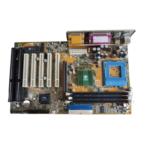
SOYO Super 7 SY-5EMA User manual

SY-5EMA+ V1.0
Super 7™
Motherboard
Quick Start Guide
FC
CTested To Comply
With FCC Standards
FOR HOME OR OFFICE USE
POST CONSUMER
RECYCLED PAPER
100%
The SOYO CD
Installation
Introduction
Quick BIOS Setup

NSTL “Year 2000 Test”Certification Letter
November 6, 1998
Testing Date: November 6, 1998
Certification Date: November 6, 1998
Certification Number: NCY2000-981106-005
To Whom It May Concern:
We are please to inform you that the “SY-5EMA+”system has passed NSTL Year 2000
certification test program. The Year 2000 test program tests a personal computer for its ability to
support the year 2000. The “SY-5EMA+: system is eligible to carry the NSTL :Year 2000
Certification”seal.
The Year 2000 certification test has been done under the following system configuration:
Company Name : SOYO COMPUTER INC.
System Model Name : SY-5EMA+
Hardware Revision : N/A
CPU Model : Intel Pentium 233/66Mhz
On Board Memory/L2 Cache : SDRAM DIMM 32MBx1 /1MB
System BIOS : Award Modular BIOS V4.51PG 09/07/1998-VP3-598B-
8669-2A5LES2BC-00
Best regards,

SOYO
3
Declaration of Conformity
According to 47 CFR, Part 2 and 15 of the FCC Rules
Declaration No.: D8D0404 Dec. 09, 1998’
The following designated product
EQUIPMENT: Main Board
MODEL NO.: SY-5EMA+
which is the Class B digital device complies with 47 CFR Parts 2 and 15 of the FCC rules.
Operation is subject to the following two conditions : (1) this device may not cause harmful
interference, and (2) this device must accept any interference received, including interference
that may cause undesired operation.
The product was tested with the following configuration:
Monitor: SONY/AK8GDM17SE2T Printer: HP/DS17XU2225
USB Mouse: WINIC/F4ZFDM-A50 PS/2 Keyboard: SILITED/GYUM99SK
PS/2 Mouse: GENIUS/FSUGMZFC Modem: ACEEX/IF AXDM1414
This declaration is given for the manufacturer
SOYO COMPUTER INC.
No.21,Wu-Kung 5 Rd., Hsing Chuang City,
Taipei Hsien, Taiwan, R.O.C.
The test was carried out by
SPORTON INTERNATIONAL INC.
6F, No. 106, Hsin TaiWu Rd., Sec. 1, His Chih,
Taipei Hsien, Taiwan, R.O.C.
SPORTON INTERNATIONAL INC.

SOYO™
4
SY-5EMA+V1.0
Super7
Motherboard
Pentium®
Class CPU supported
ETEQ82C663x PCI/AGP Motherboard
ATX Form Factor
Copyright © 1999 bySoyo Computer Inc.
Trademarks:
Soyo is a registered trademark of Soyo Computer Inc. All trademarks are the property of their
owners.
Product Rights:
Product and corporate names mentioned in this publication are used for identification purposes
only and may be registered trademarks or copyrights of their respective companies.
Copyright Notice:
All rights reserved. This manual is copyrighted by Soyo Computer Inc. You may not reproduce,
transmit, transcribe, store in a retrieval system, or translate into any language, in any form or by
any means, electronic, mechanical, magnetic, optical, chemical, manual or otherwise, any part of
this publication without express written permission of Soyo Computer Inc.
Disclaimer:
Soyo Computer Inc. makes no representations or warranties regarding the contents of this
manual. We reserve the right to revise the manual or make changes in the specifications of the
product described within it at any time without notice and without obligation to notify any
person of such revision or change. The information contained in this manual is provided for
general use by our customers. Our customers should be aware that the personal computer field is
the subject of many patents. Our customers should ensure that their use of our products does not
infringe upon any patents. It is the policy of Soyo Computer Inc. to respect the valid patent rights
of third parties and not to infringe upon or assist others to infringe upon such rights.
Restricted Rights Legend:
Use, duplication, or disclosure by the Government is subject to restrictions set forth in
subparagraph (c)(1)(ii) of the Rights in Technical Data and Computer Software clause at
252.277-7013.
About This Guide:
This Quick Start Guide is for assisting system manufacturers and end users in setting up and
installing the Motherboard. Information in this guide has been carefully checked for reliability;
however, no guarantee is given as to the correctness of the contents. The information in this
document is subject to change without notice.
If you need any further information, please visit our Web Site on the Internet. The address is
"http://www.soyo.com.tw".
* These specifications are subject to change without notice.
Version 1.1 Edition: April 1999
SY-5EMA+ V1.0
Quick Start Guide
5
Introduction
1
1
Introduction
Congratulationsonyourpurchaseofthe
SY-5EMA+V1.0
PCI/AGPMotherboard.This
QuickStartGuidedescribesthestepsforinstallingandsettingupyournewMotherboard.
ThisguideisdesignedforalluserstoprovidethebasicstepsofMotherboardsettingand
operation.Forfurther information,pleasereferto SY-5EMA+V1.0MotherboardUser's
GuideandTechnicalReferenceonlinemanualincludedontheCD-ROMpackedwithyour
Motherboard.
Unpacking
WhenunpackingtheMotherboard,checkforthefollowingitems:
Ø
TheSY-5EMA+V1.0Motherboard
Ø
ThisQuickStartGuide
Ø
TheInstallationCD-ROM
Ø
OneIDE DeviceFlat Cable
Ø
OneFloppyDiskDriveFlatCable

SY-5EMA+ V1.0 Quick Start Guide
6
Introduction
SY-5EMA+ V1.0 Motherboard Layout
Key Features
Ø
Super7
TM
Platform
Ø
512KByte/1MByteL2cache
Ø
SupportsCPUvoltagefrom2.0vto3.5v
in0.1vincrements
Ø
PC98,ACPI,UltraDMA/33
Ø
Power-onbymodemorRTCalarm
Ø
SupportsWake OnLAN (WOL)
Ø
Fan-offinSuspendmode
Ø
5x32-bitbusmasteringPCIslots
Ø
2xUSBports,1xIrDAport
Ø
Supportsmultiple-bootfunction
Ø
Y2KComplaint
Flash BIOS
JP44
1 3
JP5
1
3
AGP Slot
ISA Slot #1
3V
Lithium
Battery
®
RST
PW2
SPK
Keylock
Power
LED
Turbo
LED
HDD LED
_ _
_
_
+ +
+
+
ETEQ
®
EQ82C6638
P.B. SRAM
64Kx64
P.B. SRAM
64Kx64
TAG 32Kx8
JP10
1
3
JP9
JP8
IDE 2
1
FDC
1
IDE 1
1
DIMM 1
DIMM 2
DIMM3
SMC
®
FDC37C669Q
*
1
CPUFAN
1
PCI Slot #2
PCI Slot #3
PCI Slot #4
PCI Slot #5
PCI Slot #1
ISA Slot #2
IR 5
1
SW1
ON
USB1USB2
PS/2 Mouse
Connector
PS/2 KB
Connector
ATX Power
(Optional)
WOL
Header
SW2
ON
5316
2 4
531
2 4
CHAFAN
ETEQ
EQ82C6629

SY-5EMA+ V1.0
Quick Start Guide
7
Installation
2
2
Installation
ToavoiddamagetoyourMotherboard,followthesesimpleruleswhilehandling
thisequipment:
l
BeforehandlingtheMotherboard,groundyourselfbygraspinganunpaintedportion
ofthesystem'smetalchassis.
l
RemovetheMotherboardfromitsanti-staticpackaging.Holditbytheedgesand
avoidtouchingitscomponents.
l
ChecktheMotherboardfordamage.Ifanychipappearsloose,presscarefullytoseat
itfirmlyinitssocket.
Followthedirectionsinthissectiondesignedtoguideyouthroughaquickandcorrect
installationofyournew
SY-5EMA+V1.0
Super 7
™Motherboard.Fordetailed information,
pleaserefertoSY-5EMA+V1.0MotherboardUser'sguideandTechnicalReference online
manualincludedontheCD-ROMpackedwithyourMotherboard.
PREPARATIONS
Gatherandprepareallthenecessaryhardwareequipmenttocompletetheinstallation
successfully:
u
Pentium
®
classprocessorwithcoolingfan
u
DRAMmemorymodules
u
Computercaseandchassiswithadequatepowersupplyunit
u
Monitor
u
Keyboard
u
PointingDevice(PS/2mouse)
u
VGACard
u
SoundCard(optional)
u
Speaker(s)(optional)
u
DiskDrives:HDD,CD-ROM, Floppydrive…
u
ExternalPeripherals:Printer,Plotter,andModem-(optional)

SY-5EMA+ V1.0 Quick Start Guide
8
Installation
Install the Motherboard
Followthestepsbelowinordertoperformtheinstallationofyournew
SY-5EMA+V1.0
Super 7
™Motherboard.
Step 1. Install the CPU
TomountthePentium
®
classprocessorthatyouhavepurchasedseparately,followthese
instructions.
CPU Mount Procedure
1.
Liftthesockethandleuptoaverticalposition.
2.
AlignthebluntedgeoftheCPUwiththematchingpinholedistinctiveedgeonthe
socket.
3.
Seattheprocessorinthesocketcompletelyandwithoutforcing.
4.
ThenclosethesockethandletosecuretheCPUinplace.
RemembertoconnecttheCPUCoolingFantotheappropriatepower
connectorontheMotherboard. Thefanisakeycomponentthatwillensure
systemstability.Thefanpreventsoverheating,thereforeprolongingthelifeof
yourCPU.
12
3 4

SY-5EMA+ V1.0
Quick Start Guide
9
Installation
Step 2. Set SW2 for CPU Voltage
SW2isusedtosettheCPUcorevoltage.Pleaseverifythecorrectvoltagesettingswithyour
dealerbeforeinstallation.UsethefollowingtabletosetSW2tothepropervoltagevalue
accordingtothespecificationsmarkedonyourCPU:
Voltage Setting:
SW2
Processor Voltage
12345
3.52 V
on on on on
off
AMD K5 PR100
AMD K5 PR133
AMD K5 PR166
The AMD K5 and K6 come in several versions with different voltages.
Please verify the correct voltage settings with your dealer before
installation. The most common K5 runs on 3.52V.
AMD K6 166
AMD K6 200 2.9 V
on
off off
on
off
AMD K6 233 3.2 V
off off
on on
off
AMD K6 266
AMD K6 300
AMD K6-2 266
AMD K6-2 300
AMD K6-2 333
AMD K6-2 350
AMD K6-2 366
AMD K6-2 380
AMD K6-2 400
2.2 V
off
on
off off off
AMD K6-2 450
AMD K6-2 475
AMD K6-2 500
AMD K6-III 400
AMD K6-III 450
2.4 V
off off
on
off off
Cyrix 6x86(L) PR166+
Cyrix 6x86(L) PR200+
The Cyrix 6X86(L) and M
¢º
come in several versions with different
voltages. Please ask your dealer for the correct voltage.
Cyrix 6x86MX PR166
Cyrix 6x86MX PR200
Cyrix 6x86MX PR233
Cyrix 6x86MX PR266
Cyrix MII 300
Cyrix MII 333
Cyrix MII 350
Cyrix MII 366
Cyrix MII 380
2.9 V
on
off off
on
off
3.3 V
on
off
on on
off
Intel P54C P100
Intel P54C P133
Intel P54C P166
Intel P54C P200
The P54C (standard Pentium®) comes in several versions with different
voltages. Please ask your dealer for the correct voltage. The most
common P54C runs on 3.3V.
2.8 V
off off off
on
off
Intel P55C P166
Intel P55C P200
Intel P55C P233
The P55C (MMX) processors have the same voltage setting.

SY-5EMA+ V1.0 Quick Start Guide
10
Installation
Voltage Setting:
SW2
Processor Voltage
12345
3.52 V
on on on on
off
IDT WinChip C6/2-225*
IDT WinChip 2-266
IDT WinChip 2-300 TheIDT WinChip C6/2 comes in several versions with different. Voltage.
Please ask your dealer for the correct voltage.
IDT WinChipC6/2-200*
IDT WinChip2-233*
3.3 V
on
off
on on
off
Rise mP6 PR266
2.8 V
off off off
on
off
Step 3. Set SW1 for CPU Frequency
TheDIPswitchSW1enablesyoutoassigntheFrequencyMultiplier,CPUHostBusClock,
AGPClockandPCIClock,asshowninthefollowingtable:
Frequency Setting:
SW1
Processor Multiplier CPU
Bus
Clock JP10 JP8 JP9
123456
AMD K5 PR100 1.5x 66MHz 1-2 2-3 2-3
off off off off off off
AMD K5 PR133 2.0x 66MHz 1-2 2-3 2-3 on
off off off off off
AMD K5 PR166 2.5x 66MHz 1-2 2-3 2-3 on on
off off off off
AMD K6 166 2.5x 66MHz 1-2 2-3 2-3 on on
off off off off
AMD K6 200 3x 66MHz 1-2 2-3 2-3
off
on
off off off off
AMD K6 233 3.5x 66MHz 1-2 2-3 2-3
off off off off off off
AMD K6 266 4.0x 66MHz 1-2 2-3 2-3 on
off
on
off off off
AMD K6 300 4.5x 66MHz 1-2 2-3 2-3 on on on
off off off
AMD K6-2 266 4.0x 66MHz 1-2 2-3 2-3 on
off
on
off off off
4.5x 66MHz 1-2 2-3 2-3 on on on
off off off
AMD K6-2 300 3x 100MHz 1-2 1-2 2-3
off
on
off off off
on
5.0x 66MHz 1-2 2-3 2-3
off
on on
off off off
AMD K6-2 333 3.5x 95MHz 1-2 1-2 2-3
off off off
on
off
on
AMD K6-2 350 3.5x 100MHz 1-2 1-2 2-3
off off off off off
on
AMD K6-2 366 5.5x 66MHz 1-2 2-3 2-3
off off
on
off off off
AMD K6-2 380 4.0x 95MHz 1-2 1-2 2-3 on
off
on on
off
on
AMD K6-2 400 4.0x 100MHz 1-2 1-2 2-3 on
off
on
off off
on
AMD K6-2 450 4.5x 100MHz 1-2 1-2 2-3 on on on
off off
on
AMD K6-2 475 5.0x 95MHz 1-2 1-2 2-3
off
on on on
off
on
AMD K6-2 500 5.0x 100MHz 1-2 1-2 2-3
off
on on
off off
on
AMD K6-III 400 4.0x 100MHz 1-2 1-2 2-3 on
off
on
off off
on
AMD K6-III 450 4.5x 100MHz 1-2 1-2 2-3 on on on
off off
on
Cyrix 6x86 MX PR 166+
2.0x 66MHz 1-2 2-3 2-3 on
off off off off off
Cyrix 6x86 PR MX 200+
2.0x 75MHz 1-2 2-3 2-3 on
off off off
on
off
Cyrix 6x86 MX PR 166
2.0x 66MHz 1-2 2-3 2-3 on
off off off off off
2.5x 66MHz 1-2 2-3 2-3 on on
off off off off
Cyrix 6x86 MX PR 200
2.0x 75MHz 1-2 2-3 2-3 on
off off off
on
off

SY-5EMA+ V1.0
Quick Start Guide
11
Installation
Frequency Setting:
SW1
Processor Multiplier CPU
Bus
Clock JP10 JP8 JP9
123456
Cyrix 6x86 MX PR 233
2.5x 75MHz 1-2 2-3 2-3 on on
off off
on
off
Cyrix 6x86 MX PR 266
2.5x 83MHz 1-2 1-2 2-3 on on
off
on on
off
3.5x 66MHz 1-2 2-3 2-3
off off off off off off
Cyrix MII 300 3x 75MHz 1-2 2-3 2-3
off
on
off off
on
off
4.0x 66MHz 1-2 2-3 2-3 on
off
on
off off off
3.5x 75MHz 1-2 2-3 2-3
off off off off
on
off
Cyrix MII 333 3x 83MHz 1-2 1-2 2-3
off
on
off
on on
off
Cyrix MII 350 3x 100MHz 1-2 1-2 2-3
off
on
off off off
on
Cyrix MII 366 2.5x 100MHz 1-2 1-2 2-3 on on
off off off
on
Cyrix MII 380 3x 100MHz 1-2 1-2 2-3
off
on
off off off
on
P54C P100 1.5x 66MHz 1-2 2-3 2-3
off off off off off off
P54C P133 2.0x 66MHz 1-2 2-3 2-3 on
off off off off off
P54C/P55C P166 2.5x 66MHz 1-2 2-3 2-3 on on
off off off off
P54C/P55C P200 3x 66MHz 1-2 2-3 2-3
off
on
off off off off
P55C P233 3.5x 66MHz 1-2 2-3 2-3
off off off off off off
IDT WinChip C6/2-
200 3x 66MHz 1-2 2-3 2-3
off
on
off off off off
IDT WinChip C6/2-
225 3x 75MHz 1-2 2-3 2-3
off
on
off off
on
off
IDT WinChip 2-233 3.5x 66MHz 1-2 2-3 2-3
off off off off off off
IDT WinChip 2-266 2.33x 100MHz 1-2 1-2 2-3
off
on on
off off
on
IDT WinChip 2-300 2.5x 100MHz 1-2 1-2 2-3 on on
off off off
on
3x 66MHz 1-2 2-3 2-3
off
on
off off off off
Rise mP6 PR266 2x 100MHz 1-2 1-2 2-3 on
off off off off
on
This main board supports various CPU multiplier and host bus frequency settings.
*Please select the proper frequency setting based on specifications of the CPU you have
purchased. System stability or components damage, in case of over-specification setting, is
not guaranteed.
*
The K6-2 300 and 333 come in several versions with different host bus frequency
specifications. Please verify the correct host bus frequency settings before installation.

SY-5EMA+ V1.0 Quick Start Guide
12
Installation
JP8isusedtoindicatethefrequencyoftheCPUbusclocktotheETEQchipset.
JP9andJP10areusedtodeterminethattheSDRAMisrunningatthefrequencyofthe
CPUbusclockortheAGPclock.
CPU BUS
Clock AGPBUS
Clock PCI Clock JP10 JP8 JP9 SDRAM
Clock
66MHz 66MHz 33MHz 1-2 2-3 2-3 66MHz
75MHz 75MHz 37.5MHz 1-2 2-3 2-3 75MHz
2-3 1-2 1-2 55MHz
83MHz 55MHz 27.5MHz 1-2 1-2 2-3 83MHz
2-3 1-2 1-2 63.4MHz
95MHz 63.4MHz 31.7MHz 1-2 1-2 2-3 95MHz
2-3 1-2 1-2 66MHz
100MHz 66MHz 33MHz 1-2 1-2 2-3 100MHz
2-3 1-2 1-2 75MHz
112MHz 75MHz 37.5MHz 1-2 1-2 2-3 112MHz
2-3 1-2 1-2 82.6MHz
124MHz 82.6MHz 41.3MHz 1-2 1-2 2-3 124MHz
Note:
Use 8ns or faster SDRAM modules (for PC100) when SDRAM is set to run at
the frequency of 95/100MHz.

SY-5EMA+ V1.0
Quick Start Guide
13
Installation
Step 4. Attach Connectors
ThissectiontellshowtoconnectinternalperipheralsandpowersupplytotheMotherboard.
InternalperipheralsincludeIDEdevices(HDD,CD-ROM),FloppyDiskDrive,FrontPanel
Devices(TurboLED,InternalSpeaker,ResetButton,IDELED,and KeyLockSwitch.),
Wake-On-LANcard,VGAcard,SoundCard,andotherdevices.
FormoredetailsonhowtoconnectinternalandexternalperipheralstoyournewSY-5EMA+
V1.0Super7™Motherboard,please referto SY-5EMA+V1.0MotherboardUser'sGuide
andTechnicalReferenceonlinemanualonCD-ROM.
Connectors and Plug-ins
IrDA(Infrared Device Header):IR1 Wake-On-LAN Header:JP44
Pin1 Pin2 Pin3 Pin4 Pin5 Pin1 Pin2 Pin3
VCC None IRRX GND IRTX 5VSB GND MP-Wakeup
CPU Cooling Fan: CPUFAN Chassis Cooling Fan: CHAFAN USB
Pin1 Pin2 Pin3 Pin1 Pin2 Pin3
GND 12V SENSOR GND 12V SENSOR Connect your USB devices
to this header.
PowerLED Keylock
Pin1 Pin2 Pin3
Pin1 Pin2
5V NC GND
ControlPin GND
Speaker
Pin1 Pin2 Pin3 Pin4
5V NC NC Speakerout
HDDLED TB LED PWRBT RESET
Pin1 Pin2 Pin1 Pin2 Pin1 Pin2 Pin1 Pin2
LEDAnode LED Cathode LEDAnode LED Cathode Power On/Off GND Power Good GND
ATXPowerOn/Off:PWRBT
Connectyourpowerswitchtothisheader(momentaryswitchtype).
Toturn offthe system,pleasepress thisswitch andholddown forlonger than4 seconds.
ATXPower Supply:ATXPW
AttachtheATXPowercabletothisconnector.IfyouuseATXpowersupply.
Whenusing the Power-On by PS/2Keyboard function,please makesure theATX power supplycan
takeat least720mA load on the 5VStandby lead(5VSB) tomeet thestandard ATXspecifications.
Power LED
Key Lock
Speaker
Reset
PWRBT
Turbo LED
HDD LED
+
+
++
__
_
_

SY-5EMA+ V1.0 Quick Start Guide
14
Installation
Step 5. Configure Memory
YourboardcomeswiththreeDIMMsockets,providingsupportforupto768MBofmain
memoryusingDIMMmodulesfrom8MBto256MB.For66MHzhostbusCPUsuse12nsor
fasterDIMMmodules;for83MHzhostbusCPUsuse8nsmodules.
Memory Configuration Table
DIMM BanksMEMORY
CONFIGURATION DIMM 1 DIMM 2 DIMM 3
RAM Type EDO/SDRAM EDO/SDRAM EDO/SDRAM
Single RAM
Module Size (MB) 8/16/32/64/128/256 8/16/32/64/128/256 8/16/32/64/128/256
Step 6. Clear CMOS
CleartheCMOSmemorybymomentarilyshortingpin2-3onjumperJP5,andthenby
shortingpin1-2toretainnewsettings. Thisjumpercanbeeasilyidentifiedbyitswhite
coloredcap.
CMOS Clearing Clear CMOS Data Retain CMOS Data
JP5 Setting short pin 2-3 to
clear the CMOS Short pin 1-2 to
retain new settings
Note: You must unplug the ATX power cable from the ATX power connector when
performing the CMOS Clear operation.
3
2
1
3
2
1

SY-5EMA+ V1.0
Quick Start Guide
15
Quick BIOS
Setup
3
3
Quick BIOS Setup
Afterthehardwareinstallationiscomplete,turnthepowerswitchon,thenpressthe
<DEL>
keyduringthesystemdiagnosticcheckstoentertheAwardBIOSSetupprogram.The
CMOSSETUPUTILITYwilldisplayonscreen.Then,followthesestepstocompletethe
quickBIOSsetup.
Step 1. Select [LOAD SETUP DEFAULT]
Selectthe“LOADSETUPDEFAULT”menuandtype“Y”attheprompttoloadtheBIOS
optimalsetup.
Step 2. Select [STANDARD CMOS SETUP]
Set[Date/Time]and[Floppydrivetype],thenset[HardDiskType]to “Auto”.
Step 3. Select [SAVE & EXIT SETUP]
Press
<Enter>
tosavethenewconfigurationtotheCMOSmemory,andcontinuetheboot
sequence.

SY-5EMA+ V1.0 Quick Start Guide
16
The SOYO CD
4
4
The SOYO CD
YourSY-5EMA+V1.0Super7™Motherboardcomes withaCD-ROM labeled"SOYOCD."
TheSOYOCDcontainstheuser'smanualfileforyournewMotherboard,the drivers
softwareavailableforinstallation,andadatabaseinHTMLformatwithinformationonSOYO
Motherboardsandotherproducts.
Step 1. Insert the SOYO CD into the CD-ROM drive
TheSOYOCDwillauto-run,andtheSOYOCDStartUpMenuwilldisplayasshownbelow.
(SOYO CDStart UpProgram Menu)
TheSOYOCDStart UpProgramautomaticallydetectswhichSOYOMotherboardyouown
anddisplaysthecorrespondingmodelname.
Step 2. Read SOYO [5EMA+ V1.0] Manual
Clickthe
Read Manual
buttontoopentheuser'smanualfileofyourMotherboard.

SY-5EMA+ V1.0
Quick Start Guide
17
The SOYO CD
PleasenotethatiftheStartUpprogramwasunabletodeterminewhichSOYOMotherboard
youown,themanualselectionmenuwillpopup,asshownbelow.Thenselecttheuser's
manualfilethatcorrespondstoyourMotherboardmodelnameandclick
OK.
(ManualSelection Menu)
Theuser'smanualfilesincludedontheSOYOCDareinPDF(PostscriptDocument)format.
InordertoreadaPDFfile,theappropriateAcrobatReadersoftwaremustbeinstalledin
yoursystem.
Note:
TheStartUpprogramautomaticallydetectsiftheAcrobatReaderutilityisalready
presentinyoursystem,andotherwisepromptsyouonwhetherornotyouwanttoinstallit.
YoumustinstalltheAcrobatReaderutilitytobeabletoreadtheuser'smanualfile.Follow
theinstructionsonyourscreenduringinstallation,thenoncetheinstallationiscompleted,
restartyoursystemandre-runtheSOYOCD.
Step 3. Install Drivers and Utilities
ThefollowingdescribesthebestwayofinstallingWindows95orWindows98onyour
5EMA+V1.0Motherboard:
Ø
ThefollowingBIOSdefaultsettingsshouldnotbechanged:
1. The‘OnChipUSBController’itemunder‘ChipsetfeaturesSetup’issettoenabled.
2. The‘USBAssignedIRQ’itemunder‘PnP/PCIConfigurationissettoenabled.
YouMUSThavethesetwoitemsenabledforWindows95/98torunproperlyonyour
system.
Ø
InstallWindows95/98
Ø
IfyouinstalledWindows95youwillnowneedtoupgradeyourUSBdriverby
SOYO CD Manuals
Please select your manual in the box below
and click OK.
686 boards:586 boards:
OKBack
5EMA+ V1.0

SY-5EMA+ V1.0 Quick Start Guide
18
The SOYO CD
runningthefollowingprogramonyourWindowsCD:
Win95/OSR2/Usbsupp/USBsupp.exe
Ø
Afterinstallationofwindows,youwillneedtoinstalltheVIAdrivers.Followthe
instructionbelow.
Clickthe
EnterSOYO CD
buttontodisplaythelistofdriversthatcanbeinstalledonyour
Motherboard.Thestart-upprogramdisplaysthedriversavailableforthe5EMA+V1.0and
theWindowsversionyouuse.
(Driver InstallationMenu)
Ashortdescriptionofallavailabledriversfollows:
ØETEQ 4in1 driver package
uETEQ Southbridge Driver for Win 95
Windows95may notrecognizethe southbridgeofyourETEQchipset,firstinstallthese
drivers.
uETEQ IRQ remapping utility
Tomake surethat IRQsarehandledcorrectlybyWindows98,runthisutility.(Runthisutility
BEFOREinstallinganydrivers)
uETEQ AGP Drivers
TheETEQVxDdriverforWindows95/98mustbeinstalledtomakeuseofyourAGPcard.
(Win95:Makesurethat theETEQ SouthbridgedriversareinstalledFIRST)
Please select the driver you want to install and click OK, You will have to
restart your system after installation. Only the drivers that are relevant
to your board are displayed initially.
ETEQ 4in1 driver package
SOYO CD Xpress utility
SOYO Speedpro BusMaster Driver for win 95/98
Cancel
Display all drivers
on the SOYO CD
OK
Driver Installation

SY-5EMA+ V1.0
Quick Start Guide
19
The SOYO CD
ØSOYO SpeedPro Busmaster Driver for Win 95/98
WithoutthebusmasterdriverstheCPUwillneedtobeinvolvedeverytimedataisreadfrom
orwrittentothe Harddisk.ThebusmasterdriversmakeuseofDMA(DirectMemoryAccess)
torelievetheCPUofthisburden,thusspeedingupthesystem.
TheSOYOSpeedProdrivermakesuseofanadvancedcachingalgorithm,whichgivesitan
advantageoverotherbusmasterdrivers.
Note:Ifyou installthe SOYO SpeedPro Busmasterdriver forWindows95/98,youcan
NOTinstall the VIABusMaster drivers.
ØSOYO CD Xpress Utility
ThisutilitywillenhanceyourCD-ROMDrivedata-thoughputbyusingspaceontheHarddisk
ascache. Thiswayapplicationprogramscanaccessdatafaster.Thisutilityissuitablefor
Windows95/98.
Selectwhichdriveryouwanttoinstallandclick
OK,
orclick
Cancel
toreturntothemain
menu.WhentheinstallationprogramofadriverstartsrunningtheSOYO-CDwillexit.After
finishingtheinstallation,restarttheSOYO-CDandinstallthenextdriver.Werecommend
youtoinstallalldrivers,andtodosointherightsequence(toptobottom).
Note:
Onceyouhaveselectedadriver,thesystemwillautomaticallyexittheSOYOCDto
beginthedriverinstallationprogram.Whentheinstallationiscomplete,mostdriversrequire
torestartyoursystembeforetheycanbecomeactive.
Installthedrivers insequence,startingwiththe FIRSTdriver.
IfyouwanttoseeallthedriversavailableontheSOYO –CD,clickthe
Displayalldrivers
onthe SOYO CD
button.DoNOTinstalldriversthatarenotsuitableforyourboard,
otherwiseyoursystemmaycrash.
Step 4. Check the Latest Releases
Clickthe'CheckthelatestReleases'buttontogotheSOYO Website toautomatically find
thelatestBIOS,manualanddriverreleasesforyourmotherboard.Thisbuttonwillonlywork
ifyourcomputer isconnectedtothe internetthroughanetworkormodemconnection.Make
suretogetyourmodemconnectionupbeforeclickingthisbutton.

SY-5EMA+ V1.0 Quick Start Guide
20
The SOYO CD
Step 5. Enter the SOYO CD
Clickthe
EnterSOYO CD
buttontoentertheSOYOHTMLdatabase.TheStartUp
programwillactivatethedefaultHTMLbrowserinstalledonyoursystem(forexample,
InternetExplorerorNetscape)tovisualizethecontentsoftheSOYOCD.
TheSOYOCDcontainsusefulinformationaboutyourMotherboardandotherSOYO
productsavailable.Foryourconvenience,thisinformationisavailableinHTMLformat,
similartotheformatwidelyusedontheInternet.
(SOYO CD HTML Database in English*)
Note:
IfnoHTMLbrowserisinstalledonyoursystem,theStartUpprogramwillpromptyou
onwhetherornotyouwouldliketoinstalltheInternetExplorer*browser.ClickYEStoinstall
theHTMLbrowser.Aftertheinstallationiscomplete,pleaserestartyoursystem.Thenre-run
theSOYOCDandyouwillbeabletobrowsetheSOYOHTMLdatabase.
(*InternetExplorerisaMicrosoftTrademark)
Other manuals for Super 7 SY-5EMA
1
This manual suits for next models
1
Table of contents
Other SOYO Motherboard manuals

SOYO
SOYO 6KB Use and care manual

SOYO
SOYO SY-6BA+100 User manual

SOYO
SOYO Super 7 SY-5EMA+ Use and care manual

SOYO
SOYO SY-7IZM Use and care manual

SOYO
SOYO SY-P4S DRAGON Ultra User manual

SOYO
SOYO 82440 FX Use and care manual

SOYO
SOYO DRAGON Lite SY-KT333 User manual

SOYO
SOYO SY-7IWM-X User manual

SOYO
SOYO SY-6BA+ Use and care manual

SOYO
SOYO SY-P4I845PE User manual