Step 2. Make Connections to the Mainboard
Thissectiontellshowtoconnectinternalperipheralsandpowersupplytothemainboard.
InternalperipheralsincludeIDEdevices(HDD,CD-ROM),FloppyDiskDrive,Chassis Fan,
FrontPanelDevices(TurboLED,InternalSpeaker,ResetButton,IDELED,and KeyLock
Switch.),Wake-On-LANcard,VGAcard,SoundCard,andotherdevices.
FormoredetailsonhowtoconnectinternalandexternalperipheralstoyournewSY-6KL
Mainboard,pleasereferto SY-6KL MainboardUser's GuideandTechnicalReference online
manualonCD-ROM.
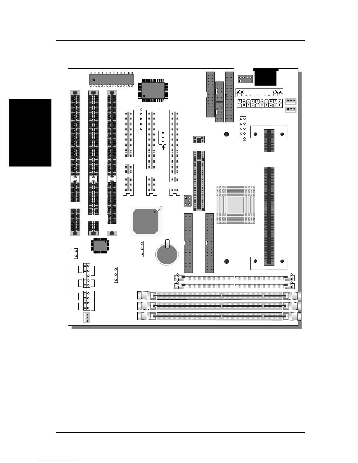
Connectors and Plug-ins
PCI Audio Card Header: SB-Link™(PC-PCI) Wake-On-LAN Header: JP44
Connect the SB-Link™(PC-PCI) cable from your
PCI audio card to this header. Connect the WOL cable from
your LAN card to JP44.
CPU Cooling Fan: FAN 1 Chassis Fan: FAN 3
Connect the CPU cooling fan cable to the
FAN1 power connector. Connect the case cooling fan cable to the
FAN3 power connector.
USB TB LED SPK
Plug your USB devices
to this header. Connect your Turbo LED
cable to this header. Connect the speaker cable to
this header.
RESET IDE LED KB-LOCK
Connect the reset button
to this header. Connect the IDE device
LED to this header. Connect the Power LED and
the KB Lock switch to this
header.
IrDA (Infrared Device Header): IR1 AT Power Supply
Connect the cable from your IrDA device to this
header. Connect the AT Power Supply
cable to this connector
ATX Power On/Off: PWRBT ATX Power Supply: ATX PW
Connect your power switch to this
header (momentary switch type).
Depending on the BIOS setting,
turning off the system is done by
“one touch”or by pressing the
switch for >4s longer than 4s.
ATX Power Select: JPW1
If you use a non-standard ATX power
supply, open this jumper.
Attach the ATX Power cable to this
connector.
When using the PS/2 Keyboard Wake-Up
function, please make sure the ATX
power supply can take at least 720mA
load on the 5V Standby lead (5VSB) to
meet the standard ATX specifications.