SP Shocker CVO User manual

WWW.SHOCKERPAINTBALL.COM 1
PLEASE READ CAREFULLY
SHOCKER CVO
OWNER’S MANUAL

2SHOCKER CVO WWW.SHOCKERPAINTBALL.COM 3
PLEASE READ CAREFULLY PLEASE READ CAREFULLY
Assemble and install the included
barrel. Make sure The Freak®XL insert
is installed inside the barrel back.
Install the assembled barrel in the
front of the Shocker®CVO body.
Take care not to cross-thread any
barrel components during assembly
or installation, as permanent
damage may result.
The Shocker®CVO is equipped with
a cross bolt trigger safety. When
pressed from the left, the safety
engages to prevent the trigger from
being pulled. When pressed from
the right, exposing the red o-ring on
the left side of the grip frame, the
Shocker®CVO is live and ready to
re. The trigger safety should never
be relied upon in place of a barrel
blocker.
Carefully screw a professionally lled paintball
High Pressure Air (HPA) system into the Air
Source Adapter (ASA).
Slowly turn the ASA knob clockwise to gently
charge the Shocker®CVO with air.
01 BARREL 02 BARREL BLOCKER & LOADER
03 TRIGGER SAFETY 04 TURN ON AIR
05 ADJUST VELOCITY
Velocity must be measured and adjusted to below 300 feet per
second (91.4 meters per second) before each session of use.
Velocity must be tested and adjusted at the start of each paintball session. Fill the loader with paintballs and turn
it on. While wearing ASTM compliant paintball goggles in an area where all bystanders are protected, remove the
barrel blocker and re over a chronograph to measure the velocity. Using a 5/32-inch hex key, turn velocity up
(clockwise) or down (counter-clockwise) as needed to meet the eld’s standard. After each adjustment take 2 or
three shots to allow pressure to stabilize, then re over a chronograph to check velocity. For safety and to avoid
internal damage, never adjust the Shocker® CVO to re at greater than 300 feet per second.
TABLE OF CONTENTS
QUICK START - VELOCITY ADJUSTMENT
TABLE OF CONTENTS
GASSES
TRIGGER ADJUSTMENT
ADJUSTMENT/TUNING
LOADER
FEEDNECK ADJUSTMENT
QEV FORCE ADJUSTMENT
ROUTINE MAINTENANCE
BOLT
DETENTS
ASA
ADVANCED MAINTENANCE
REGULATOR
GRIP FRAME
TRIGGER
PILOT VALVE
BOLT CONTROL / QEV
TROUBLESHOOTING
PARTS GUIDE
WARRANTY
TECH SUPPORT
–THE SHOCKER®CVO IS NOT A TOY.
–MISUSE OF THE SHOCKER®CVO MAY RESULT
IN SERIOUS INJURY OR DEATH.
–EYE PROTECTION DESIGNED FOR PAINTBALL
USE MUST BE WORN BY THE USER AND ANY
PERSON WITHIN RANGE OF THE
SHOCKER®CVO.
– SP RECOMMENDS THAT THE SHOCKER®CVO
ONLY BE SOLD TO PERSONS 18 AND OLDER.
– THOROUGHLY READ THE SHOCKER®CVO
OPERATION AND INSTRUCTION MANUAL
BEFORE OPERATING.
CVO SPECS
OPERATING PRESSURE
PROPELLANT
OPERATION
MODES OF FIRE
ANTI-CHOP SYSTEM
BARREL THREAD
LUBRICANT
145 psi
High Pressure Air
Pneumatic
1
Low-Force Bolt
Autococker
GR33SETM
Turn knob slowly!
A quick pressure surge
may cause damage.
-+
QUICK START
ON
02
03
04
05
06
06
07
08
09
10
11
14
15
16
16
18
20
39
39
CONTENTS
Install a high-performance paintball loader
in the locking feedneck. In order to
perform its at its best, the Shocker®
CVO must be consistently fed unbroken
paintballs rapidly.
Slide the included barrel blocker over the end of
the Shocker® CVO barrel. Sling the blocker’s cords
over the back of the marker and snug them tight.
The barrel blocker is a critical piece of safety
equipment and must always be used when the
Shocker®CVO is handled outside of an active
paintball eld.

4SHOCKER CVO WWW.SHOCKERPAINTBALL.COM 5
PLEASE READ CAREFULLY PLEASE READ CAREFULLY
GASSING The Shocker®CVO is equipped with a bottom-line
style air source adapter (ASA). Before screwing an HPA system
into the ASA, make sure the ASA is turned off by loosening the
ASA knob on its front [FIG 8]. Take care not to turn the ASA knob
too far.
After screwing the HPA system into the ASA, air is released into
the marker by tightening the ASA knob [FIG 4]. It is important to
turn the knob slowly. Once air can be heard entering the marker,
wait until the hissing stops before turning the ASA knob further
to fully open the HPA regulator. This will protect the internal
components from a sharp rise in pressure, ensuring longer life.
DEGASSING AND UNLOADING After use the Shocker®CVO
should be unloaded and degassed. In some jurisdictions,
paintball markers are legally required to be unloaded and de-
gassed before they are transported on public roads.
The ASA is turned off by rotating the ASA knob counter-clockwise
(loosening). When the knob is twisted far enough to turn the ASA
off, a small amount of air will vent from the ASA with a brief
hissing sound. This is normal. Do not turn the knob any further.
Turning off the ASA does not completely depressurize the
Shocker®CVO and may leave enough gas inside the marker to
re 2 or more shots.
In a safe area (all persons protected by paintball goggles and or
netting, such as a paintball eld’s chronograph area) remove the
loader from the Shocker®CVO.
Tip the Shocker CVO®to dump any paintballs from the breech.
Remove the barrel blocker and switch the safety to the live
position, exposing its red o-ring. Dry-re in a safe direction until
the bolt no longer cycles with each trigger pull. Put the barrel
blocker back on and unscrew the HPA system from the grip ASA.
Take care to ensure that the HPA tank does not unscrew from its
regulator when unscrewing the regulator from the ASA.
The Shocker® CVO is designed to be powered by a high-pressure
compressed air (HPA) system only. Use of carbon dioxide
(CO2) to power the Shocker®CVO is likely to cause damage to
GASES
sensitive internal seals and will result in a voided warranty. HPA
systems with a 3000psi or 4500psi capacity can be utilized on
the Shocker®CVO. HPA systems with output pressures between
450psi and 850psi can be used with the Shocker®CVO.
An output pressure of 550psi is recommended for maximum
consistency at high rates of re. HPA systems are shipped
empty, and must only be lled by properly trained personel.
LOOSEN ASA KNOB 06
REMOVE HPA SYSTEM 07
Do not to unscrew HPA tank from its regulator!
OFF
Never put oil or other petroleum products in a compressed air
regulator or tank—only use manufacturer specied lubricants
or cleaners.
A
After any trigger adjustments, the safety must be checked
to ensure that it still performs properly. If the safety cannot
be engaged, loosen either the magnetic tension or
pre-travel screw.
Adjusting the magnetic tension screw outward (counter-
clockwise) increases the distance between the magnet and
adjustment screw, and results in a lighter trigger pull. Turning
the screw in provides a stronger magnetic pull allowing for a
more responsive trigger return. The strongest trigger resistance
is achieved when the magnetic tension screw is able to make
contact with the trigger return magnet when the trigger is at rest.
PRE-TRAVEL This set screw is located at the top of the trigger
behind the magnetic tension set screw. Adjusting this set screw
will alter the forward travel of the trigger pull. [FIG.08 B] The
length of the trigger pull is determined by where the trigger stops
in its forward position and how far back it can be pulled.
POST-TRAVEL This adjustment is accessed by placing the allen
wrench at a slight angle from the left hand side of the marker.
[FIG. 08 D] Adjusting this set screw will alter the rearward travel
length of the trigger pull. The trigger must come to a stop with
the activation lever against this set-screw. [FIG. 08 C] Backing
out the screw far enough to allow the CVO™ pilot valve to stop
rearward motion of the trigger may result in pilot valve damage
and premature leakage.
ACTIVATION LEVER TENSION The spring tension on the
activation lever which actuates the CVO™ pilot valve is adjusted
by changing which hook inside the grip frame is used for its
return spring. [FIG. 08 E] Decreasing activation lever tension can
lighten trigger pull, but care should be taken to any adjustment
here as too little tension will result in the system not resetting
consistently for follow-up shots. The Shocker CVO is factory-
congured at maximum activation lever tension (third hook
position down from the top). If a non-force-fed loader is used,
this is the desired setting to limit rate of re and reduce feed
issues.
The trigger activation set-screw in the front face of the trigger
is calibrated at the factory to compensate for manufacturing
variance in the trigger body. This set-screw should not be
adjusted as improper-alignment can prevent correct operation
of the trigger safety and result in premature pilot valve leakage.
Even if someone on the Internet says adjusting this screw will
provide a better trigger pull don’t do it. Just don’t.
The Shocker®CVO has four main points of trigger adjustment
which may be set with a 1/16" allen key. This provides the
ability to ne-tune the perfect trigger for any style of play. Every
paintball player is unique with individual tastes. The Shocker®
CVO trigger is easy to tailor for an ideal t. Adjustment should
only be performed with the marker unloaded and degassed.
MAGNETIC TENSION This set screw is located at the top of the
trigger; it is the set screw closest to the trigger guard. Adjusting
this set screw will alter the weight of the trigger pull. [FIG. 08 A]
B
C
D
ADJUSTMENT POINTS 08
TRIGGER ADJUSTMENT
E

6SHOCKER CVO WWW.SHOCKERPAINTBALL.COM 7
PLEASE READ CAREFULLY PLEASE READ CAREFULLY
LOADER / FEEDNECK
LOADER It is highly recommended that the Shocker® CVO be
paired with a force-feed loader to obtain best performance on
the eld [Fig 09]. With no eyes and a modern short feed-neck, the
Shocker®CVO requires fast, responsive feeding to achieve rapid
rates of re without chopping paint.
Force feed loaders can be identied by the gentle spring pressure
that can be felt constantly pushing paintballs outward from their
neck, even when turned on their side or upside-down. Examples
of force feed loaders include Dye Rotor™, Empire Prophecy™ and
Empire Halo™.
Some players may still wish to opt for loaders that are not force-
feed, to reduce the risk of a jam in the loader and put less force
on brittle paint. Examples of non-force-fed loaders include the
Virtue Spire™, Valken VSL™, GI LVL™ and classic Viewloader
Revolution™.
If using a non-force-feed loader, make sure that the Shocker® CVO
Activation Tension is at its maximum (see Trigger Adjustment)
and reduce bolt force with the bolt force adjustment (see QEV).
FEEDNECK ADJUSTMENT Although the size of loader
feednecks is standardized within the paintball industry, there are
typically small variances in diameter between manufacturers,
and even between different loaders of the same model type.
The Shocker®CVO is equipped with an adjustable feedneck
ensuring that it can securely grip loaders with a wide range of
feedneck sizes. The feedneck’s clamping mechanism is best
adjusted with the clamp lever open.
Simply turning the clamp lever will close down or open up the
clamp mechanism. Finer adjustments can be made by twisting
the thumbwheel [Fig 10]. Test t after adjustment. The feedneck
should have a rm grip on the loader, but the lever should not be
difcult to close or open.
QEV ADJUSTMENT Bolt closing force has a signicant impact
on how a paintball marker res, both in terms of the marker’s
ability to handle paintballs and felt recoil. This is extremely
important in a mechanical marker like the Shocker®CVO.
Without anti-chop eyes, low bolt force becomes more important
to reliable operation. The quick exhaust valve (QEV) in the
Shocker®CVO air manifold includes an adjustment screw that
can be used to restrict air ow in front of the bolt’s sail, providing
a wide adjustment range over bolt closing force.
The bolt force adjustment screw [FIG. 11] is set with a 1/16"
hex wrench through a small hole in the top of the grip frame,
just in front of the trigger guard. As with trigger adjustment, a
ball-end hex wrench will allow easier access to this adjustment
screw. When the screw is backed out all the way out (counter-
clockwise) the exhaust air ow path is wide open, providing
minimal air resistance against the closing bolt for the fastest
possible ring rates.
Turning the bolt-force adjustment screw in (clockwise) creates
a smaller path for air to escape. As a result, a pocket of air acts
as a cushion to balance against the air pushing the bolt to its
forward position. With a decreased net force pushing it forward,
the bolt closes more slowly.
A fast moving bolt has the obvious advantage of being able
to re at a faster rate, while a slower bolt reduces recoil for
improved accuracy and reduced breakage of thin-shelled brittle
tournament grade paintballs.
BOLT FORCE ADJUSTMENT 11
QEV
10 FEEDNECK CLAMP ADJUSTER
09 LOADER

8SHOCKER CVO WWW.SHOCKERPAINTBALL.COM 9
PLEASE READ CAREFULLY PLEASE READ CAREFULLY
DETENTS The ball detents in the Shocker®CVO prevent double-
feeding and subsequent chopping of paintballs by preventing
them from rolling forward until they are pushed into the barrel
by the bolt. Optional low-prole green detents [FIG. 17D] may
be installed for better reliability with extremely large or out of
round paint.
Each detent extends into the breech under spring pressure until
it is pushed out of the way by the paintball and bolt during the
ring cycle. If a paintball is broken in the marker, or dirt is able to
get in through the feedneck, the ball detents can become stuck,
either not extending into the breech to do their job, or stuck in the
breech, blocking proper bolt movement. In either case, cleaning
the detent system is a simple process.
DETENT CLEANING With the marker unloaded and degassed,
a 5/64-inch hex key can be used to unscrew the detent cover
screws [FIG. 16]. Finger pressure against the detent from inside
the breech is enough to unseat the detent covers so they can be
removed from either side of the Shocker®CVO. This will allow
access to the detents [FIG. 17A] for inspection and cleaning.
Cotton or foam swabs are ideal for cleaning the small nooks in
and around the detent. In severe cases, the detent may need to
be removed from the detent cover by pulling the hooked top of
the detent hinge pin with an o-ring pick [FIG. 17B] while taking
care not to lose the detent or spring [FIG. 17C] when they are
released and lifted away. Cleaning the detent assembly is all that
is needed for routine maintenance. Do not lubricate the detent
or the detent cover screw o-ring. The o-ring must provide friction
to lock the screw in place, and grease will gum up the detent.
Care should be taken not to cross-thread or over-tighten the
detent cover screw as this may cause permanent damage to the
Shocker®CVO body.
The Shocker®CVO utilizes a spool valve design which combines
its bolt with its main exhaust valve for a system that uses few
parts for efcient performance with few possible failure points.
Occasionally the bolt system may need to be cleaned. It also
should be lubricated after each day’s use as regular maintenance.
No tools are required for this procedure.
REMOVAL With the Shocker®CVO unloaded and degassed,
pressing on the bolt release latch [FIG. 12] will cause the end-
cap to pop out. In its extended position, the end-cap serves as a
handle to pull the entire bolt assembly from the marker body as
a single unit [FIG. 13].
CLEANING Unscrewing the ring can [FIG. 15A] from the main
chamber [FIG. 15D] provides access to the bolt [FIG. 15B] for
cleaning and inspection. All parts of the bolt assembly should
be wiped free from paint or other debris with a soft cloth. All o-rings
should be inspected for tears, at spots or other visible damage
and replaced if necessary. Before re-assembly all o-rings should
be greased lightly with GR33SETM. The outer surface of the bolt’s
mid-section should also receive a very light coat of GR33SETM. Oil
or other lubricants may cause damage and should not be used.
REASSEMBLY Care should be taken when re-assembling the valve
assembly. The greased parts should not be set on a dirty surface
where they will pick up dust or sand particles that can prevent
o-rings from obtaining a good seal. With the bolt placed in the
chamber guide [FIG. 15C] and the chamber guide seated in the main
chamber, the ring can should be screwed gently into place. The
complete bolt assembly can then be pushed into the body of the
Shocker®CVO until the latch mechanism makes an audible click,
locking everything in place with the rear cap ush against the body.
A B C D
12 RELEASE LATCH RELEASE LATCH 16
13 BOLT ASSEMBLY REMOVAL
14 INSTALLING BOLT ASSEMBLY
15 BOLT ASSEMBLY COMPONENTS A
B
C
D
DETENT REMOVAL 17
BOLT CLEANING DETENTS

10 SHOCKER CVO WWW.SHOCKERPAINTBALL.COM 11
PLEASE READ CAREFULLY PLEASE READ CAREFULLY
TM
ASA KNOB The ASA Knob may occasionally need to be removed
for cleaning or lubrication, especially if the Shocker®CVO has
taken a hard dive into a muddy or sandy bunker, driving debris
into the ASA around its knob. As with all maintenance, this must
be done only with the Shocker®CVO unloaded and degassed.
Unscrew the ASA Knob, as if turning the air supply off, but
continue unscrewing until the knob comes free of the ASA
[FIG 18].
The screw threads of the ASA may be lubricated with GR33SETM,
but only place an extremely thin layer of GREESETM on the
pin. Excess grease can clog the ASA’s lter. Take care when
reinstalling the ASA knob, to be sure it is not cross-threaded.
ASA POSITION The ASA position may be adjusted to achieve
a custom balance or t with different air systems. To move
the ASA, remove the ASA knob, and use a 3/32-inch hex key to
loosen the ASA lock screw [FIG 19] one-half turn. Slide the ASA
to the desired position, then lock it in place by tightening the ASA
lock screw. Reinstall the ASA knob.
REMOVAL To remove the ASA, follow the ASA position
directions, but further loosen the ASA lock screw until it allows
the ASA to slide free of the grip frame. When reinstalling the
ASA, very lightly lubricate the air rail seal assembly face with
GREESETM and press it into the frame with thumb pressure to
make sure it sits ush with the rail. Slide the ASA forward until
it is ush with the front of the grip frame, then tighten the ASA
lock screw.
DISASSEMBLY Full disassembly is only necessary to replace a
leaking pin o-ring. This is accomplished by using a 7/64-inch hex
wrench to unscrew the stainless nut from the back of the ASA.
Seated in the front of the stainless nut is the ASA pin o-ring. This
should be inspected and replaced if it shows any signs of wear
or damage.
Removal of the regulator’s internal components is an advanced
maintenance procedure that should only be performed when
needed to repair a leak or lubricate seals if velocity becomes
inconsistent with fresh, good quality paint and a clean bolt
assembly.
SPRING PLATFORM REMOVAL With the Shocker®CVO
unloaded and degassed, use a 5/16-inch hex key to unscrew the
spring platform base [FIG.. 21] from the vertical regulator portion
of the marker’s body. If the hex key cannot t far enough into the
spring platform to get a good grip, use a 5/32-inch hex key to
turn the velocity adjuster inward (counter-clockwise, it is reverse
threaded) to expose more of the hexagonal ats in the spring
platform. The adjuster spring is now attached to the back of the
reg piston (VRG205) and will not drop freely.
SPRING PLATFORM ASSEMBLY Additional parts will come
out, stacked inside the spring platform. These include the
spring guide [FIG. 22A], regulator washer [FIG. 22B], relief valve
[FIG. 22C], relief valve spring [FIG. 22D] and velocity adjuster
[FIG. 22E]. The spring guide acts as a positioning seat for the
regulator spring. The velocity adjuster is the base on which the
spring guide sits. Turning the velocity adjuster changes the
elevation of the spring platform to put more or less pressure
on the regulator spring, ultimately determining the gas pressure
inside the Shocker®CVO. The relief valve is a miniature, non-
adjustable regulator that vents air out through the middle of the
velocity adjuster if the Shocker®CVO is in danger of becoming
over-pressurized.
REGULATOR PISTON Reach inside with an o-ring pick or
needle nose pliers and pull the piston out by its spring to pull the
regulator piston out [FIG. 23]. This is a difcult step. Patience
and a gentle hand are required to achieve success. Take care not
to slip and scratch the inner walls of the regulator body, as this
may cause non-repairable leaks that will prevent the regulator
from working correctly.
18 ASA KNOB SPRING PLATFORM 21
19 ASA LOCK SCREW SPRING PLATFORM ASSEMBLY 22
A
B
C
D
E
F
20 ASA DISASSEMBLY
ASA REGULATOR

12 SHOCKER CVO WWW.SHOCKERPAINTBALL.COM 13
PLEASE READ CAREFULLY PLEASE READ CAREFULLY
REGULATOR
Removal of the regulator’s internal components is an advanced
maintenance procedure that should only be performed when
needed to repair a leak or lubricate seals if velocity becomes
inconsistent with fresh, good quality paint and a clean bolt
assembly.
SPRING PLATFORM REMOVAL With the Shocker®CVO
unloaded and degassed, use a 5/16-inch hex key to unscrew
the spring platform base [FIG.. 22F] from the vertical regulator
portion of the marker’s body. If the hex key cannot t far enough
into the spring platform to get a good grip, use a 5/32-inch hex
key to turn the velocity adjuster inward (counter-clockwise, it is
reverse threaded) to expose more of the hexagonal ats in the
spring platform. The adjuster spring is now attached to the back
of the reg piston (VRG205) and will not drop freely.
SPRING PLATFORM ASSEMBLY Additional parts will come
out, stacked inside the spring platform. These include the
spring guide [FIG. 22A], regulator washer [FIG. 22B], relief valve
[FIG. 22C], relief valve spring [FIG. 22D] and velocity adjuster
[FIG. 22E]. The spring guide acts as a positioning seat for the
regulator spring. The velocity adjuster is the base on which the
spring guide sits. Turning the velocity adjuster changes the
elevation of the spring platform to put more or less pressure
on the regulator spring, ultimately determining the gas pressure
inside the Shocker®CVO. The relief valve is a miniature, non-
adjustable regulator that vents air out through the middle of the
velocity adjuster if the Shocker®CVO is in danger of becoming
over-pressurized.
REGULATOR PISTON Reach inside with an o-ring pick or
needle nose pliers and pull the piston out by its spring to pull the
regulator piston out [FIG. 23]. This is a difcult step. Patience
and a gentle hand are required to achieve success. Take care not
to slip and scratch the inner walls of the regulator body, as this
may cause non-repairable leaks that will prevent the regulator
from working correctly.
REGULATOR
REGULATOR BASE Unscrew the regulator base from inside the
regulator body with a 1/4-inch hex key. Once it is completely
unscrewed, the regulator base [FIG 24] will need to be pulled
from the regulator body with an o-ring pick, as was done with
the regulator piston. Take great care not to scratch the regulator
face, the at surface surrounding the small opening in the center
of the regulator base.
INSPECTION Carefully inspect and clean all removed
components. Any seals or o-rings which show signs of wear
or have dents or tears must be replaced. Pay special attention
to the regulator seat, the small seal pressed into the tip of the
regulator piston [FIG 25]. This seal, like many of the o-rings is a
wear item and will eventually need to be replaced. A small, light
circular depression in the regulator seat from where it presses
up against the face in the regulator base is normal and not a
problem. A deep circular depression, or chips or tears which are
not a part of that circular imprint will lead to leaks and are a sign
that the seal must be replaced. When replacing the regulator
seat, take care not to misplace the regulator tip lter which sits
below the regulator seat.
LUBRICATION Use GR33SETM to lightly lubricate all o-rings
except the o-ring inside the spring platform. This o-ring must
provide friction to keep the velocity adjuster locked in to its
setting. Do not lubricate the regulator seat in the tip of the piston.
REASSEMBLY The regulator components are reinstalled in the
reverse order of disassembly. Both the regulator base and spring
platform must be screwed in all the way for proper regulator
operation. When testing the Shocker CVO after performing
regulator maintenance, always wear paintball eye and face
protection, even if only dry ring with no paintballs.
23 PISTON REMOVAL REGULATOR BASE 24
REGULATOR SEAT 25

14 SHOCKER CVO WWW.SHOCKERPAINTBALL.COM 15
PLEASE READ CAREFULLY PLEASE READ CAREFULLY
GRIP FRAME
Removal of the grip frame is an advanced maintenance
procedure that should only be performed when needed to repair
a leak or replace a damaged component.
RUBBER GRIP The wrap-around grip must be removed to make
some trigger adjustments, or to be replaced with custom grips.
This is achieved by using a 5/64-inch hex key. The grip frame
is compatible with grips that t a M1911 pistol, allowing the
Shocker® CVO to use a wide variety of at panel or wrap-around
style custom grips.
GRIP FRAME It is not necessary to remove the rubber grip
before separating the grip frame from the Shocker®CVO body,
but it can help make sure all parts are correctly aligned
when reinstalling.
Grip the top edge of the rubber foregrip and pull it down an inch,
or completely remove it from the Shocker®CVO so that it does
not interfere with alignment of the grip frame to the body
when reinstalling.
Before removing the grip frame, the bolt assembly must be
removed from the Shocker®CVO. Use a 1/8-inch hex key to
remove the front and rear grip frame screws [FIG. 26A]. Gently
slide the grip frame away from the receiver. A small metal mesh
lter screen (FLT006) sits inside the grip frame’s air outlet just
behind the pushbutton safety [FIG. 26B]. Take care not to drop
or lose this lter, it is necessary to trap ne dust that could
cause the pilot valve to stick or leak. If the lter is lost, obtain a
replacement as soon as possible.
REASSEMBLY Reassembling the grip frame to the body is a
reverse of the removal process. Make sure the air lter is in the
grip frame and clean and inspect the gas-though seal [FIG.27],
lightly lubricating it with GR33SETM. Make certain the short arm
of the QEV pin [FIG. 31C] is on the right side of the marker, facing
forward so that it will line up with its slot in the grip frame.
TRIGGER
TRIGGER The Shocker®CVO pivots on a pair of bearing sets
nested onto a low friction pin. The grip frame will need to be
removed from the body in order to provide access for trigger
removal. Using a 1/16-inch hex wrench, unscrew and remove the
trigger pivot pin [FIG. 28] and the trigger may be removed from
the top of the grip by pivoting it around the safety while sliding
it up and out.
26 GRIP FRAME TRIGGER 28
27 GAS-THRU SEAL
B
A
A

16 SHOCKER CVO WWW.SHOCKERPAINTBALL.COM 17
PLEASE READ CAREFULLY PLEASE READ CAREFULLY
PILOT VALVE
PILOT VALVE Disassembly of the pilot valve should only be
performed when necessary for repair. The internal parts of the
pilot valve are small and fragile and must be handled with care.
If necessary, use a magnifying glass to inspect and work with
these parts.
After removing the grip frame from the body use a 1/4-inch
wrench to unscrew the valve cap. The pilot valve’s upper o-ring
[FIG. 29] will remain seated inside the valve body, and it may
be removed with an o-ring pick. Inspect, clean and if necessary
replace this o-ring. Like the other o-rings in the pilot valve, the
upper o-ring should be very lightly lubricated with GR33SETM.
An o-ring pick can be used to remove the pin cage [FIG. 30E]
from the pilot valve cap. The pin cage keeps the upper o-ring
seated. The valve pin [FIG. 30D] is held in place by the its clip
[FIG. 30A] and spring [FIG. 30B]. To remove it, pry the clip loose
from the pin with an o-ring pick, taking care to retain both parts.
The pin may then be removed from the opposite side so that
the lower o-ring [FIG. 30C] may be cleaned, inspected and if
necessary replaced. Clean and inspect the valve pin to be sure
it is not bent, and has a smooth surface with no chips around
the edge of its top end or where it steps from a larger to smaller
diameter in its middle.
The valve cap’s outer o-ring should also be cleaned, inspected
and if necessary replaced when the valve is apart.
Reassembly of the pilot valve is done in the reverse order of
disassembly. Take care not to apply excessive bending stress
on the valve pin when reattaching its clip.
BOLT CONTROL
29 PILOT VALVE O-RING BOLT CONTROL MANIFOLD The bolt control manifold [FIG.
31E] connects the supply of regulated compressed air to the
pilot valve and the forward control section of the bolt assembly.
At the front of the bolt control manifold is the rebuildable quick
exhaust valve (QEV) [FIG. 31D] that vents air from the control
section when the bolt closes to re the Shocker®CVO.
Using a 1/16-inch hex key, remove the QEV mount screw [FIG.
32A]. Using a 1/8-inch hex key unscrew the gas-though bolt [FIG.
32B] from the manifold inlet at the rear.
Once removed, the bolt control assembly may be further
disassembled as needed for repair. The QEV slides off of the
manifold. The QEV may be disassembled by removing its pin
[FIG. 31C], sliding out the QEV core [FIG. 31A] and pushing the
QEV diaphragm [FIG. 31B] out with a 1/16-inch hex key. The bolt
control manifold [FIG. 31E] slides out of the pilot valve [FIG. 31F].
The trigger return magnet is secured in the bolt control manifold
by dimpling the aluminum manifold body with a hardened steel
punch. It is non-removable.
REASSEMBLY Before reassembly, lubricate o-rings very
sparingly with GR33SETM. Excess lubricant can clog small gas
paths in the pilot valve or QEV, preventing proper operation. Do
not lubricate the QEV diaphragm.
Reassemble in reverse order of removal and disassembly.
When reassembling, be sure the cone in the center of the QEV
diaphragm is pointed back, toward the pilot valve.
B
D
E
A
F
32 REMOVE MANIFOLD ASSEMBLY
31 MANIFOLD ASSEMBLY
30 PILOT VALVE
AB C D E
A
B
C

18 SHOCKER CVO WWW.SHOCKERPAINTBALL.COM 19
PLEASE READ CAREFULLY PLEASE READ CAREFULLY
TROUBLESHOOTING TROUBLESHOOTING
AIR LEAKS OUT THROUGH THE VELOCITY ADJUSTER.
•Damaged or worn seal in spring platform assembly causing
continuous leak - Inspect clean and if necessary replace o-rings
and relief valve seal from spring platform assembly following
the instructions in the Regulator section of this manual.
•Damaged or worn regulator piston or regulator base o-rings or
regulator seat causing intermittent leak - Damaged components
causing the regulator to “run hot” will result in the relief valve
repeatedly venting excess pressure through the velocity
adjuster. Inspect, clean and if necessary replace all regulator
o-rings and seals.
•Visit shockerpaintball.com for leak point images to identify
cause of leak.
AIR LEAKS OUT THROUGH THE MIDDLE REGULATOR VENT HOLE.
•One of the following o-rings is damaged or worn: regulator
piston o-ring, inner or lower outer regulator base o-ring - Clean
inspect and if necessary replace bad o-rings following the
instructions in the Regulator section of this manual.
•Visit shockerpaintball.com for leak point images to identify
cause of leak.
AIR LEAKS OUT THROUGH THE TOP REGULATOR VENT HOLE.
•One of the upper two regulator base o-rings is damaged or worn
- Clean inspect and if necessary replace bad o-rings following
the instructions in the Regulator section of this manual.
•Visit shockerpaintball.com for leak point images to identify
cause of leak.
AIR LEAKS OUT THROUGH THE LOWER REGULATOR VENT HOLE.
•Damaged or worn outer spring platform o-ring - Clean, inspect
and if necessary replace the outer spring platform o-ring
following the instructions in the Regulator section of this manual.
•Visit shockerpaintball.com for leak point images to identify
cause of leak.
THE TRIGGER DOES NOT MOVE WHEN PULLED.
•Trigger is out of adjustment - Adjust the trigger following the
instructions in the Trigger Adjustment section of this manual
•Loosen trigger pivot pin slightly.
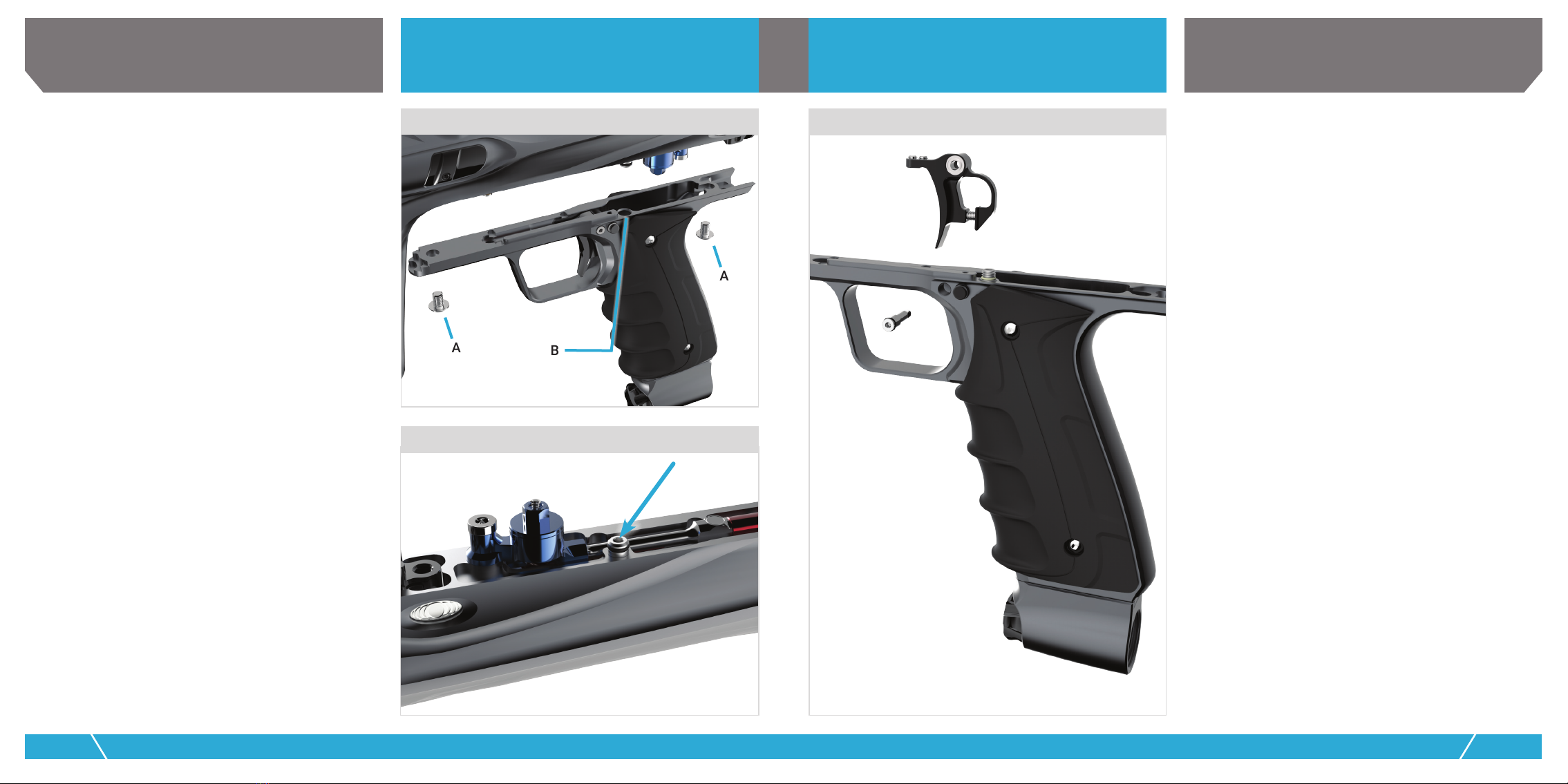
WHEN GASSED UP AIR LEAKS FROM BETWEEN THE GRIP
FRAME AND BODY.
•Manifold assembly o-rings may be damaged or worn - Inspect,
clean and if necessary replace o-rings in the manifold assembly
following the instructions in the Bolt Control section of this
manual.
•Gas through seal is damaged or worn - Inspect, clean and
if necessary replace the gas-through seal following the
instructions in the Grip Frame section of this manual.
•Grip frame is not fully seated into body - Check to make sure the
grip frame is fully seated in the body. An improperly positioned
QEV pin may prevent the grip frame from fully seating.
WHEN GASSED UP, LITTLE OR NO AIR SEEMS TO BE
GETTING TO THE SHOCKER®.
•Bolt cannot move - Follow the Bolt Cleaning section of this
manual to clean and inspect the o-rings of the bolt system.
•Filter is clogged – see the grip frame removal section of this
manual to locate and inspect the lter at the gas through port.
BOLT ASSEMBLY WILL NOT SLIDE SMOOTHLY INTO BODY
OR LOCK IN PLACE.
•O-rings are damaged or un-seated - Follow the bolt cleaning
procedure and make sure all o-rings are in good condition and
properly seated. Also make sure there is no debris inside the
body. Pressing the bolt release button before the Shocker®
CVO has been de-gassed is a common cause of un-seated
o-rings and should be avoided.
WHEN GASSED UP, THE BOLT IMMEDIATELY CLOSES.
•Trigger is stuck in the ring position – Make sure that debris or
dirt has not jammed the trigger into the ring position. Clean
as needed to resolve.
•Trigger is mis-adjusted and is not releasing the pilot valve –
Make sure the trigger moves forward far enough to allow the
front of the activation lever to rise, releasing the pilot valve.
See the trigger adjustment section of this manual.
•QEV diaphragm is damaged or stuck open – See the bolt
control section of this manual.
•Pilot valve is leaking internally – Make sure pilot valve pin is
straight and unblemished, and that the lower internal pilot
valve o-ring is in good repair. See the pilot valve section of this
manual.
AIR LEAKS DOWN THE BARREL WHEN GASSING UP.
•One or more o-rings in the bolt system are damaged are worn
•Clean and inspect, following the instructions in the Bolt
Cleaning section of this manual. Pay special attention to the
inner o-ring of the chamber guide [FIG. 18C].
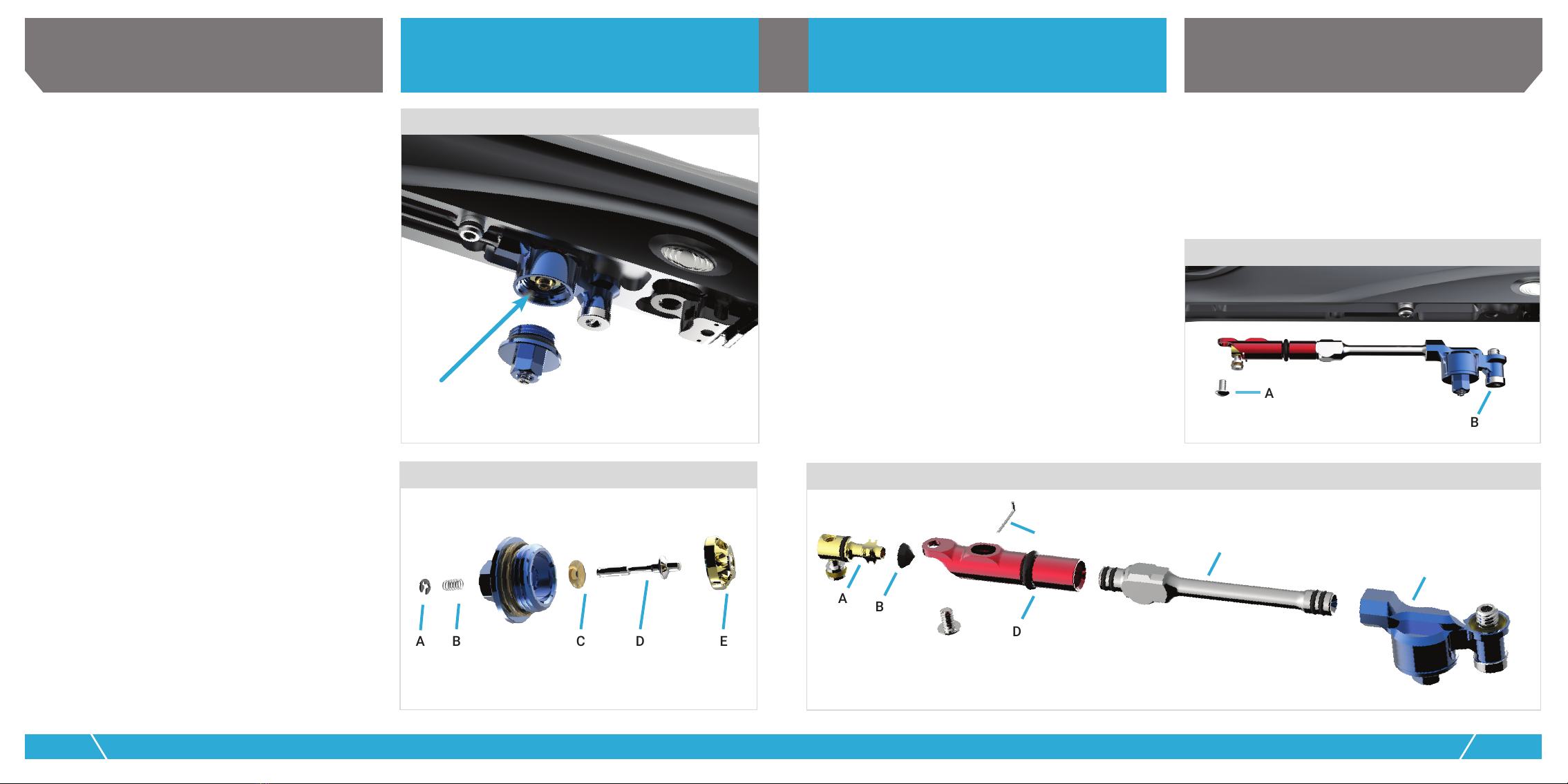
WHEN GASSED UP AIR LEAKS FROM THE BOTTOM OF THE
GRIP FRAME.
•One of the o-rings or face seal of the air rail seal assembly
is damage, dirty or missing. Inspect, clean and if necessary
replace these seals. See the ASA section of this manual.
SHOCKER®CVO WILL NOT FIRE WHEN TRIGGER IS PULLED.
• System is not pressurized with air – See the quick start section
of this manual.
•Safety is engaged – See the quick start section of this manual.
•Trigger is not engaging activation lever – See the trigger
adjustment section of this manual.
•Activation lever is stopped by post travel adjustment screw
before pilot valve is actuated – See the trigger adjustment
section of this manual.
GRIP FRAME WILL NOT FIT CORRECTLY TO BODY.
•QEV pin incorrectly aligned – Make sure the pin locking the
QEV body in place (see bolt control section of manual) is
correctly aligned. If it is pushed too far into the QEV, it will
extend out the other side and interfere with a ridge in the
grip frame.
•Trigger too far forward. The spring pressure of the activation
lever will push and lock the trigger into a forward position
that prevents the grip frame from tting to the body. Reset
the activation lever and hold the trigger in place following the
instructions in the grip frame section of this manual.
SHOCKER®CVO SUFFERS FROM FIRST SHOT DROP OFF.
•Shocker® CVO res at a low velocity or will not re on the
rst trigger pull after sitting still for a few minutes, but res
at proper velocity on all subsequent shots, this rst shot
drop off may be caused by dirt or under-lubrication. Degas,
disassemble, clean and inspect the bolt assembly following
the instructions in the Bolt Cleaning section of this manual.
SHOCKER®CVO IS BREAKING PAINT IN THE BREECH OR BARREL.
• Paint is too large for barrel - Check paint to barrel t and if
necessary switch to a larger bore FreakTM insert or smaller paint.
•Paint is inconsistent in size or shape - Old paint or paint that
is lumpy and out of round will not shoot well. Switch to fresh,
good quality paintballs.
•Turn bolt speed adjust screw in all the way (clockwise) to slow
down forward bolt speed.
•Ball detents are damaged or dirty - Inspect and clean the ball
detents as described in the Ball Detent section of this manual.
•Paint is brittle - Decreasing the bolt closing force will adapt the
Shocker®CVO to be extra gentle with brittle paintballs. See the
QEV Adjustment section of this manual.
•Loader is too slow - Upgrade to a force-feed loader or increase
the activation lever tension to its maximum setting (see trigger
adjustments).

20 SHOCKER CVO WWW.SHOCKERPAINTBALL.COM 21
PLEASE READ CAREFULLY PLEASE READ CAREFULLY
PARTS GUIDE PARTS GUIDE
CHAMBER GUIDE
OB7M06
(18x3mm)
APPLY GR33SE™
LIGHTLY
OM7017
APPLY GR33SE™
OM7020 (3x)
APPLY GR33SE™ LIGHTLY
SHK208
FIRING CAN
SHK110
OB7017
OM7014
DOW33 GREASE
APPLY GR33SE™ LIGHTLY

22 SHOCKER CVO WWW.SHOCKERPAINTBALL.COM 23
PLEASE READ CAREFULLY PLEASE READ CAREFULLY
BOLTMAIN CHAMBER
CLP003
BUM004
SPR016
OM9020 (2x)
OB7M14
(19 x 1MM)
OB7017
OM7014
OU7013
OM7015
OM7017
OM7010
(2x)
OM7017 OM7020 (3x)
OB7M06
(18 x 3MM)
SHK123
SHK205
SHK103
SHK304.2
SHK304.1
SHK110
SHK256
SHK208
OM7020
OM7010 (2x)
LIGHTLY
APPLY GR33SE™
OU7013
OM7015
OM7017
APPLY GR33SE™
APPLY GR33SE™
TO SURFACE
SHK256
PARTS GUIDE PARTS GUIDE

24 SHOCKER CVO WWW.SHOCKERPAINTBALL.COM 25
PLEASE READ CAREFULLY PLEASE READ CAREFULLY
VALVE MANIFOLD BOLT CONTROL MANIFOLD
008
3MM x 1MM
003
USE ORING TOOL (FXT030) TO SLIDE OB7M04 ONTO XTC122
012
0B7008
0U7003
SHM118
SHM116
0U7003
0B7M04
(3 X 1MM)
OB7012
SHM115
XTC122
SOS017
(RED LOCTITE 277)
SPR039
CLP010
SOS017
CLP010
OB7008 - AS008 buna 70 durometer
OB7M04 - 3mm x 1mm buna 70 durometer
OU7003 - AS003 urethane 70 durometer
OB7013 - AS013 buna 70 durometer
SOS017 - #4-40 x .125" black oxide set screw
SHM 2.0 VALVE ASM GUIDE
GOG PAINTBALL S.A.
THE INFORMATION CONTAINED IN THIS DRAWING IS THE SOLE PROPERTY OF
GOG PAINTBALL S.A. ANY REPRODUCTION IN PART OR WHOLE WITHOUT THE
WRITTEN PERMISSION OF GOG PAINTBALL S.A. IS PROHIBITED.
SHM VALVE ASM
SHM217
MAG005
OB7M22
(3.5 x 1MM)
OB7M22
(3.5 x 1MM)
SSB001
2.0 QEV ASM
PARTS GUIDE PARTS GUIDE

26 SHOCKER CVO WWW.SHOCKERPAINTBALL.COM 27
PLEASE READ CAREFULLY PLEASE READ CAREFULLY
QEV ASSEMBLY BODY SCREWS AND BARREL
SOS005 (2x)
STK016
OB7018
OB7018
AAMFXL09
FRKBXL02
SHK102
OB7M25
(.76 x 3.48MM)
OM9M01
(4 x 1MM)
PARTS GUIDE PARTS GUIDE
SHK239
SHK125
QEV105
OB7008
OB7M04
(3 x 1MM)
OB7M04
(3 x 1MM)
SHK224
PIN012
OB7M04
(3 x 1MM)
NO O-RING INSTALLED
WHEN USED FOR
SHOCKER CVO

28 SHOCKER CVO WWW.SHOCKERPAINTBALL.COM 29
PLEASE READ CAREFULLY PLEASE READ CAREFULLY
LATCH ASSEMBLY DETENT COVER
SHK122
PIN013 (2x)
SSS014 (2x)
(BLUE LOCTITE 242)
SHK121
SHK220
SPR017 (2x)
OB7M01
(1 x 1MM)
SHK312 (LEFT)
SHK313 (RIGHT)
SPR036
PIN011
SHK242
SHK111
DO NOT GREASE!
PARTS GUIDE PARTS GUIDE

30 SHOCKER CVO WWW.SHOCKERPAINTBALL.COM 31
PLEASE READ CAREFULLY PLEASE READ CAREFULLY
CLAMPING FEEDNECK REGULATOR PISTON
SHK133
QLK205
QLK206
SHK134
OB9004
HKA102
SSC001
SPR0l5
(FULLY INSERTSPRING INTO
BOTTOM OF VRG205)
OB7012
VRG106
INSTAL L VRGI06 INTO VRG105
ENSURE IT IS INSTALLED FLAT AND SITS
SLIGH TLYABOVE THE TIP OF VRG105
OM7014
APPLY GR33SE™
OB7012
SPR015
(FULLY INSERT SPRING INTO
BOTTOM OF VRG205)
VRG205
INSTALL VRG106 INTO VRG105
ENSURE IT IS INSTALLED FLAT
AND SITS SLIGHTLY ABOVE THE
TIP OF VRG205
PARTS GUIDE PARTS GUIDE

32 SHOCKER CVO WWW.SHOCKERPAINTBALL.COM 33
PLEASE READ CAREFULLY PLEASE READ CAREFULLY
SPRING GUIDE REGULATOR BASE
OM7006
OB7012
SHK128
SHK226
OU7010
APPLY GR33SE™
OB7014
APPLY GR33SE™
OM7010
APPLY GR33SE™
OB7010
APPLY GR33SE™
PARTS GUIDE PARTS GUIDE

34 SHOCKER CVO WWW.SHOCKERPAINTBALL.COM 35
PLEASE READ CAREFULLY PLEASE READ CAREFULLY
SPRING PLATFORM BASE REGULATOR SPRINGS
OM7012
SHK129
SHK127
OB7014
SPR015
OM7014
VRG205
VRG106
SPR032
OM7010
OB7014
OB7010
OU7010
SHK226
OB7012
OM7006
OB7014
OM7012
SHK127
SHK129
SPR035
VRG107
SHK130
SHK128
OM7012
PARTS GUIDE PARTS GUIDE

36 SHOCKER CVO WWW.SHOCKERPAINTBALL.COM 37
PLEASE READ CAREFULLY PLEASE READ CAREFULLY
BOTTOM LINE ASA TRIGGER
BRG002
BRG002
SHM207
SOS016
SHK237
SHM236
SSS017
SHK138
OU9005
(DOW33 GREASE)
OB7010
(ON KNOB BEHIND THREAD)
PARTS GUIDE PARTS GUIDE

38 SHOCKER CVO WWW.SHOCKERPAINTBALL.COM 39
PLEASE READ CAREFULLY PLEASE READ CAREFULLY
TECH SUPPORT
Our Technical Support Department is open Monday
through Friday, from 10am to 6pm EST, and can be reached
at 724-520-8690. Additional support and downloadable
product manuals are available through our web site:
www.shockerpaintball.com.
Shocker Paintball warrants to initial retail purchaser that the
Shocker®CVO paintball marker is free from defects in materials
and workmanship for one year from date of purchase. This
warranty is limited to the repair or replacement of defective
parts with the customer to pay shipping costs. Disposable wear
items (o-rings, spings, seals, screws, rubber grips, etc.) are
not warranted. This warranty does not cover surface damage
(scratches and nicks) damage resulting from misuse, improper
disassembly, reassembly or attempts to drill holes or otherwise
modify the marker. Trigger alteration of any kind may result in
serious injury and will void the warranty. The only authorized
lubricant for the Marker is Dow 33 based lubricant (GR33SETM).
Use of any other lubricant may invalidate warranty. This warranty
is effective only if the customer registers the product online at
shockerpaintball.com within 30 days of purchase. Warranty is
non-transferrable.
SSB009
2.5MM x 1MM
004
013014
SHM206
SPR040
SHM ASA ASM
SHM205
SPR038
OU7014
OU9013
SSB009 (4x)
NME116
SHM TRIGGER ASM
SHM
LEVER
ASM
SPR007
BAL001
OB7004 (2x)
PIN025 (2x)
PIN024
OB7M03
(2.5 X 1MM)
OS8M02
(3x1MM)(RED SILICON)
SHM108
PIN024
PIN025
FLT006
SSS018
BLUE LOCTITE
242
BAL001
SSS018 - 6-32 x .500 socket set screw stainless
SSB009 - 6-32 x .250 socket button head stainless
PIN025 - .094 diameter x .500 length acetal pin
PIN024 - custom pin supplied by GOG
OB7004 - AS004 buna 70 durometer
OU7014 - AS014 urethane 70 durometer
OU9013 - AS013 urethane 90 durometer
OB7M03 - metric 2.5 x 1MM buna 70 durometer
SHM 2.0 TRGGR FRAME ASM GUIDE
GRIP FRAME
PARTS GUIDE WARRANTY
Table of contents
Other SP Paintball Equipment manuals