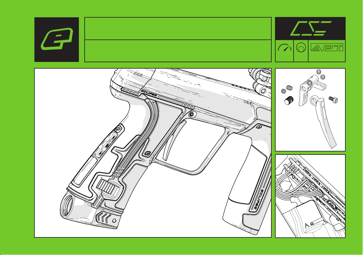
PLANET ECLIPSE CS3 User manual
Other PLANET ECLIPSE Paintball Equipment manuals

PLANET ECLIPSE
PLANET ECLIPSE EGO LV1 User manual

PLANET ECLIPSE
PLANET ECLIPSE MG 100 User manual

PLANET ECLIPSE
PLANET ECLIPSE ETHA3 User manual

PLANET ECLIPSE
PLANET ECLIPSE GEO IV CORE User manual

PLANET ECLIPSE
PLANET ECLIPSE 180R.68CAL Instruction manual

PLANET ECLIPSE
PLANET ECLIPSE ETHA2 User manual

PLANET ECLIPSE
PLANET ECLIPSE CS3 .68CAL Instruction manual

PLANET ECLIPSE
PLANET ECLIPSE GMEK User manual

PLANET ECLIPSE
PLANET ECLIPSE EGO LV2 Instruction manual

PLANET ECLIPSE
PLANET ECLIPSE Eclipseblade E2 User manual

PLANET ECLIPSE
PLANET ECLIPSE Etek STAR Frame User manual

PLANET ECLIPSE
PLANET ECLIPSE GTEK M170R User manual

PLANET ECLIPSE
PLANET ECLIPSE SL Series Owner's manual

PLANET ECLIPSE
PLANET ECLIPSE GEO 4 User manual

PLANET ECLIPSE
PLANET ECLIPSE GEO2 User manual

PLANET ECLIPSE
PLANET ECLIPSE GSL User manual

PLANET ECLIPSE
PLANET ECLIPSE emek fl 3-way valve User manual

PLANET ECLIPSE
PLANET ECLIPSE EMF100 User manual

PLANET ECLIPSE
PLANET ECLIPSE EGO TEN User manual

PLANET ECLIPSE
PLANET ECLIPSE LV1.6 User manual