manuals.online logo
Brands
  1. Home
  2. •
  3. Brands
  4. •
  5. Space Pak
  6. •
  7. Heat Pump
  8. •
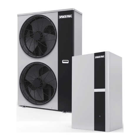
  9. Space Pak Solstice ILAHP48 User manual

Space Pak Solstice ILAHP48 User manual

ILHP2-0722
IN UNITED STATES: 260 NORTH ELM ST. WESTFIELD, MA 01085 800-465-8558 / FAX (413) 564-5815
IN CANADA: 7555 TRANMERE DRIVE, MISSISSAUGA, ONTARIO, L5S 1L4 (905) 670-5888 / FAX (905) 670-5782
SECTION 1: INTRODUCTION .......................................... 2
Hazard Denitions
Benets and Features
Specications
Performance
Typical System Diagram
SECTION 2: INSTALL ATION............................................ 6
Choose The Correct Heat Pump
Installation Location
Water Loop Connection
Electrical Connections
Control Input Connections
Control Output Connections
Dimensions
Required Clearances
SECTION 3: GLYCOL/WATER SYSTEM ......................... 10
SECTION 4: WIRING ........................................................ 12
Control Wiring Connection
Wiring Diagrams & Denitions
SECTION 5: REMOTE TOUCHSCREEN DISPLAY ........ 15
Overview of Remote Touch Screen
Electrical System Diagram
Display Windows and Functions
SECTION 6: PARAMETERS ............................................ 33
SECTION 7: TROUBLESHOOTING ................................. 50
SECTION 8: REPLACEMENT PARTS ............................. 52
WARRANTY ...................................................................... 53
MODEL ILAHP
INVERTER EXTREME
LOW AMBIENT
AIR-TO-WATER
HEAT PUMP
INSTALLATION AND
OPERATION MANUAL
Warranty
Registration
– 2 –
ILAHP Inverter Extreme Air-to-Water Heat Pump
Benets and Features
Inverter Compressor
ILAHP Inverter Extreme Heat Pump uses Inverter technology to
precisely match the heating or cooling load.
Advanced Controls
Unit function is managed by a parametric microprocessor allowing
on site adjustment to match specific operating requirements.
Easy Installation
The monobloc configuration keeps all refrigerant outdoors with
no refrigeration connection or handling done on site. Only the
water/antifreeze mixture is plumbed indoors.
Quiet Operation
The insulated housing, advanced fan profile, and variable speed
fan and compressor all combine to achieve a low noise level of
47dBA to 57dBA @ 3 meters.
Efficient Energy Transfer
ILAHP Inverter Extreme heat pump is equipped with high
efficiency, large surface area energy exchangers for both the air
to refrigerant heat transfer and the refrigerant to water energy
transfer.
Low Ambient Temperature Cooling Operation
ILAHP Inverter Extreme heat pump is capable of operating in
cooling mode in ambient temperatures as low as 5°F.
Enhanced Vapor Injection
Compressor and refrigeration system are optimized for efficient
and powerful heating performance in ambient temperatures as
low as -22°F (-30°C).
SECTION 1: INTRODUCTION
Read Before Proceeding
Hazard Denitions
The following terms are used throughout this manual to bring
attention to the presence of potential hazards or to important
information concerning the product.
Indicates an imminently hazardous situation, which
if not avoided, WILL result in death, serious injury or
substantial property damage.
Indicates an imminently hazardous situation, which
if not avoided, COULD result in death, serious injury
or substantial property damage.
Indicates an imminently hazardous situation, which
if not avoided, MAY result in minor injury or property
damage.
Used to notify of special instructions on installation,
operation or maintenance, which are important to
equipment, but not related to personal injury hazards.
Failure to comply with these recommendations will void the warranty.
– 3 –
ILAHP Inverter Extreme Air-to-Water Heat Pump
Specication
Units ILAHP48
Cooling
Capacity Range BTU/hr 24,226-63,466
Efciency Range EER 7.26-10.41
Efciency IPLV 18.4
Delivered Water Temp Range DegF 42-77
Ambient Temp Range DegF 5-109
Heating
Capacity Range BTU/hr 15,354-63,807
Efciency Range COP 1.64-5.41
Delivered Water Temp Range DegF 59-130
Ambient Temp Range DegF -22 - 109
CEC Data
Cooling Capacity* BTU/hr 45,424
Cooling Efciency* EER 8.59
Heating Capacity** BTU/hr 53,214
Heating Efciency** COP 2.78
Heating Capacity*** BTU/hr 36903
Heating Efciency*** COP 1.82
Electrical
Power V/Ph/Hz 230/1/60
Fan Motor A .8 (2)
Compressor Motor A 30
MCA A 45
MOPD A 50
SCCR kA 10
Refrigerant
Type R410a
Factory Charge lbs. 6.2
Normal Pressure Low Side PSIG 145
Normal Pressure High Side PSIG 435
Fan
Quantity 2
Power Input W 75
Type EC
Max Speed RPM 750
Sound (@3meters) Range dBA 47-57
Hydronic
Rated Flow GPM 10
Max Water Temp DegF 130
Piping Connections inch 1-1/4 NPT
Rated Pressure Drop PSI (ft W.C.) 12.8 (29.5)
Compressor
Type GMCC Rotary Inverter EVI
Speed Range HZ 30-90
Quantity 1
Dimensions
Net Dimensions (L x W x H) inch 39 x 16 x 52
Shipping Dimensions (L x W x H) inch 42 x 17 x 53
Net Weight lbs. 349
Shipping Weight lbs. 388
CEC is California Energy Commission. Data is tested in accordance with AHRI 550/590
* = 44F LWT 54F EWT @10 GPM & 95F DB Ambient
** = 120F LWT 107F EWT @10 GPM & 47F DB Ambient
*** = 120F LWT 110F EWT @10 GPM & 17F DB Ambient
ILAHP Air-to-Water Heat Pumps modulate capacity based upon outlet water temperature. Temperatures shown above are
delivered water temperature. Refer to the following performance charts to see the expected.
– 4 –
ILAHP Inverter Extreme Air-to-Water Heat Pump
ILAHP Heating Performance
(all data based on pure water and rated flow)
ILAHP Cooling Performance
(all data based on pure water and rated flow)
1
2
3
4
5
6
7
8
9
10
11
12
13
14
15
16
17
18
19
20
21
22
23
24
25
0
10000
20000
30000
40000
50000
60000
70000
-22-13 -4 5 10.4202330 35.640 44.6505968778695
COP
rh/UTB,yticapaCgnitaeH
Ambient Temperature, °F
95°F Leaving Water Te mperature, Heang
Maximum Capacity
Minimum Capacity
COP @ Maximum Capacity
COP @ Minimum Capacity
6
7
8
9
10
11
12
13
14
15
16
17
18
19
20
0
10000
20000
30000
40000
50000
60000
70000
80000
81 88 95 102 109
EER
rh/UTB,yticapaCgnilooC
Ambient Temperature, °F
45°F Leaving Water Temperature, Cooling
Maximum Capacity
Minimum Capacity
EER @ Maximum Capacity
EER @ Minimum Capacity
1
2
3
4
5
6
7
8
9
10
11
12
13
14
15
16
17
18
19
20
0
10000
20000
30000
40000
50000
60000
-22-13 -4 510.420233035.64044.6505970778595
COP
rh/UTB,yticapaCgnitaeH
Ambient Temperature, °F
131°F Leaving Water Temperature, Heang
Maximum Capacity
Minimum Capacity
COP @ Maximum Capacity
COP @ Minimum Capacity
0
1
2
3
4
5
6
7
8
9
10
11
12
13
14
15
16
17
18
19
20
21
22
23
24
25
0
10000
20000
30000
40000
50000
60000
70000
-22-13 -4 5 10.4202330 35.640 44.6505970778595
COP
rh/UTB,yticapaCgnitaeH
Ambient Temperature, °F
113° Leaving Water Temperature, Heang
Maximum Capacity
Minimum Capacity
COP @ Maximum Capacity
COP @ Minimum Capacity
5
6
7
8
9
10
11
12
13
14
15
16
17
18
19
20
0
10000
20000
30000
40000
50000
60000
70000
80000
90000
81 88 95 102 109
EER
rh/UTB,yticapaCgnilooC
Ambient Temperature, °F
48°F Leaving Water Temperature, Cooling
Maximum Capacity
Minimum Capacity
EER @ Maximum Capacity
EER @ Minimum Capacity
– 5 –
ILAHP Inverter Extreme Air-to-Water Heat Pump
Typical System Diagram
*Autoll system is suggested but not required by SpacePak. If such installation is desired or required by local code, the
Autoll MUST draw from a reservoir of pre-mixed glycol/water solution. Filling directly from a well or municipal water
source may introduce contaminants and will dilute the glycol solution in the event of a system leak.
This may impact warranty coverage.
Basic Heat Pump Installation
Heat Pump Installation with Domestic Hot Water Offset
Heat Pump Installation with Auxiliary Back-Up Heat
– 6 –
ILAHP Inverter Extreme Air-to-Water Heat Pump
SECTION 2: INSTALLATION
Choose the Correct Heat Pump
Perform appropriate load calculation to determine required
heating or cooling load for the project. Refer to specifications in
this manual to determine proper size heat pump.
Installation Location
• ILAHP heat pump must be installed outdoors, in a location
capable of supporting the full weight, plus any potential snow
load. The outdoor unit must be secured to the support with
sufcient hardware to withstand any potential wind or seismic
conditions without shifting or tipping. Additionally, the outdoor
unit should be installed with enough clearance to allow for
condensate roll-off during the defrost cycle. This will prevent
freezing under the unit during defrost.
• The heat pump should be located away from sources of heat
or moisture such as combustion vents, dryer vents, building
exhausts, etc.
• Proper clearances shown on following page must be respected.
Water Loop Connection
Please read below for water piping instructions:
• The piping must be clean and free from dirt. Prior to insulating
the pipe, it is suggested that a leak test be performed to ensure
no water leaks are present.
• The system must be supplied with a pump sized to provide
the minimum ow rate specied in the Glycol/Water System
Design section of this manual. Pump selection must consider
the pressure loss through the plumbing system and its
components, plus the pressure loss through the Heat Pump’s
internal heat exchanger. The pump must be rated for the full
range of heated or chilled water temperatures, as well as any
anti-freeze or corrosion inhibitor additives.
• The piping system should have a wye strainer installed, on the
inlet side, that is sized properly for the anticipated ow rate
and pressure drop for the application. This will help protect
internal components of the heat pump against sediments,
contaminants and fouling that could damage the unit
• Do Not use the heat pump for DIRECT heating of potable
water. The heat exchanger and internal components are not
suitable for this application.
• Do not use the heat pump to DIRECTLY heat or chill pool
water, open process water, untreated well or municipal water,
or any working uid other than aqueous Ethylene Glycol or
Propylene Glycol solution circulating in a sealed, pressurized,
and oxygen free system.
• Warning! Never expose the ILAHP Hydronic circuit to pressures
in excess of 30 PSI. Loss of coolant, property damage, or
equipment damage may result.
• The total system must be protected with a Pressure Relief
Valve or valves sized to protect the system component with
the lowest pressure rating. In no instance shall this exceed
30PSI.
• Caution! It is the responsibility of the installing contractor
to ensure that sufcient Propylene Glycol concentration is
maintained in the hydronic circuit to provide freeze protection
in all foreseeable conditions. Failure to do so voids the
warranty and damage caused by freezing is not covered.
Electrical Connections
ILAHP Heat Pump must be connected to an individual 230V
(220V-240V) circuit, sized and protected according to the
Minimum Circuit Ampacity and Max Overload Protection ratings
specied on the rating label afxed to the exterior of the unit.
The power connection must include a Protective Earth Ground
and a properly sized Neutral as two separate conductors in
accordance with National Electric Code and all local codes.
When using the ILAHP as a single standalone heat pump called
on by external inputs, (Thermostat, SSIC, Zoning controller etc.)
the voltage free wiring should be connected according to the
Field Wiring Diagram, to the terminals listed below.
Control Input connections
Important: All of the inputs are for voltage free relay contacts.
No voltage should ever be introduced to these inputs. Doing so
will immediately destroy the control and such damage will not be
covered under warranty.
Remote On/Off is a master unit enable. This must be closed for
all unit operation. This connection is located at the power input
panel at the front of the unit.
Heat/Cool On/Off is the input for space conditioning. This must
be closed for operation in either Heating or Cooling mode. This
connection at the power input panel at the front of the unit.
Remote Heat/Cool is the space conditioning mode selection.
Open results in Cooling operation, Closed results in Heating
operation. This connection is located at the power input panel at
the front of the unit.
DHW On/Off enables the Domestic Hot Water mode. When the
contacts are closed, the ILAHP Control monitors the (potable)
Domestic Water temperature and automatically changes
over to maintain the DHW temperature according to the
parameters selected. This connection is located in the electrical
compartment under the top cover.
TT input is from a 10kW thermistor sensor monitoring the DHW
Tank Temperature. This connection is located in the electrical
compartment under the top cover.
– 7 –
ILAHP Inverter Extreme Air-to-Water Heat Pump
Control Output Connections
Circulation Pump provides line to neutral power (110-120VAC)
or Line to Line (220-240V) of up to ve amps to operate the
primary circulator between the heat pump and the buffer tank.
This is switched by the ILAHP control according to the selected
parameters. This connection is located at the power input side
access panel.
The electrical loads given in the Specication Table, allow for a
pump load of no more than 5 amps and 110 VAC (2.5 amps at 230
VAC). If the pump load exceeds this, provide a separate power
source to the pump. DO NOT feed power to the pump from the
SpacePak air handler panel.
If the circuit is turned on remotely, it must still have the ability to
operate for the unit's freeze protection or the warranty will be void.
Caution: If the circulator is controlled by an external source, it
must still respond to a call from the heat pump, in order to allow
to operate for the unit's freeze protection. Disabling this will void
the unit warranty.
110V/60 Hz 3 Way Valve provides line to neutral power (110-
120VAC) of up to ve amps to operate a Three way Valve. This
is energized when the ILAHP control changes over to DHW
operation. This connection is located in the electrical compartment
under the top cover.
110V/60 Hz Hot Water Pump provides line to neutral power
(110-120VAC) of up to ve amps to operate the circulator on the
Secondary (Potable) side of the DHW heat exchanger. This is
energized when the DHW operation is active. This connection is
located in the electrical compartment under the top cover.
AUX Output provides two staged relay contacts capable of
switching 24 to 240VAC at a low current to operate a contactor
which engages electric, or any supplemental heat source,
according the selected parameters. This connection is located
at the power input side access panel. The staging logic is
controlled by Parameters H18 and R35.
AUX Heat Outputs AUX HEAT 1 & 2 are 230V signal outputs
intended to actuate a contactor or relay. They do not supply
current to power any heating device. Any attempt to connect a
heating element directly to these points will immediately render
the heat pump inoperative and may cause permanent damage
to the primary control board.
Alarm Output This sends a 230V signal to the ALARM OUT
terminals when any fault or condition causes the heat pump to
shut down, or prevents it from starting. This can be connected to
a visual or audible device to alert a custodian that the heat pump
requires immediate attention.
Communication Connections RS485 connections are
provided for two-way serial communication via Modbus protocol
to external Building Management and Monitoring equipment.
DI07 to GND on the ILAHP control board must be connected
to a Normally Closed over temp safety switch located at the
supplemental heat source. The switch must open if the safe
maximum temperature is exceeded, and this will immediately
open the AUX Output contacts. This feature must be employed
when any supplemental heat source is used. This connection is
located in the electrical compartment under the top cover.
The Remote Display output is a pigtail with a ve-conductor
female plug located inside the top compartment. The Display has
a short connector that can be plugged directly into this pigtail for
commissioning, and a 20m (66’) connection cable is provided to
mount the display permanently in a suitable interior mechanical
space. This cable can be extended up to 600’ by using 24 AWG
shielded ve-conductor cable and splicing it into the connection
cable.
– 8 –
ILAHP Inverter Extreme Air-to-Water Heat Pump
Dimensions
Unit Dimensions (inch (mm))
ILAHP
Top View
Front View
ILAHP
Side View
– 9 –
ILAHP Inverter Extreme Air-to-Water Heat Pump
Required Clearances
Unit shall be mounted per
local codes and high enough
off ground to allow for proper
condensate drainage
– 10 –
ILAHP Inverter Extreme Air-to-Water Heat Pump
SECTION 3: GLYCOL/WATER SYSTEM
Table 1 ILAHP Glycol Concentrations (10% Minimum, 50% Maximum)
Ethylene Glycol % 10 20 30 40 50
Min. Ambient Temp for Operation 23°F/-5°C 14°F/-10°C 2°F/-17°C -13°F/-25°C -36°F/-38°C
SpacePak Capacity Multiplier 0.98 0.96 0.93 0.91 0.89
Pressure Drop Multiplier (Cooling) 1.06 1.12 1.16 1.25 1.36
Pressure Drop Multiplier (Heating) 1.06 1.12 1.16 1.22 1.28
Minimum Expansion Volume / System Volume
Heating and Cooling (Gallons) 1 gallon expansion per 15 gallons system volume
Heating only, HP only (Gallons) 1 gallon expansion per 20 gallons system volume
Heating Only, with Boiler (Gallons) 1 gallon expansion per 15 gallons system volume
Propylene Glycol % 10 20 30 40 50
Min. Ambient Temp for Operation 26°F/-3°C 18°F/-8°C 8°F/-13°C -7°F/-22°C -29°F/-34°C
SpacePak Capacity Multiplier 0.99 0.98 0.96 0.93 0.88
Pressure Drop Multiplier (Cooling) 1.10 1.20 1.34 1.5 1.65
Pressure Drop Multiplier (Heating) 1.10 1.20 1.34 1.46 1.5
Minimum Expansion Volume / System Volume
Heating and Cooling 1 gallon expansion per 15 gallons system volume
Heating only, HP only 1 gallon expansion per 20 gallons system volume
Heating only, with Boiler 1 gallon expansion per 15 gallons system volume
Non use of propylene glycol will void warranty.
* A 35% concentration will prevent solid freezing, and protect from bursting, in all conditions. However, this solution
will become a thick sludge at extremely low temperatures, possibly resulting in pump overloading, pump damage, or
high pressures. Therefore this concentration should only be used in systems that will remain inactive during the winter.
Use the higher value shown for systems that must start and run at the coldest temperatures.
– 11 –
ILAHP Inverter Extreme Air-to-Water Heat Pump
Glycol/Water System Design
The ILAHP has a recommended ow that should be maintained
during all operation. The value is 10 Gallons per Minute, and
should be considered a minimum. At this ow, the pressure drop
through the heat pump is 12.8 PSI, or 29.5 ft WC, or 88 kPa.
These head loss values are based upon pure water, see Table 1
for multipliers to correct for various concentrations of anti-freeze
solution. Head Loss values shown are for the heat pump only,
the selected circulator must be capable of overcoming the entire
system head loss.
Note: these are the recommended ow values. Should the ow
drop signicantly below this value, the heat pump will shut down.
This is not an indication of a fault in the heat pump, but rather
points to insufcient pump or plumbing capacity, or air trapped
within the system.
Glycol/Water Mixture
Automotive glycol is not suitable for use in the ILAHP
system. Over time it may leave deposits which will
degrade the performance and damage pumps or
other devices in the system. Use only ethylene
glycol or propylene glycol mixtures specically
labeled for boiler or HVAC use.
Obtain all components specied in the Typical System Diagram.
Make sure all components and piping comply with applicable
local codes.
DO NOT use galvanized pipe anywhere in the system.
Galvanizing will react with the glycol and can cause glycol
degradation and sludge in the system.
• Conrm charge of expansion tank is 12-15 PSIG (with no
water or pressure in the system).
• Install the system piping. DO NOT connect the heat pump
unit to the system piping until the system has been cleaned
as required below.
The ILAHP must NOT be connected to the system during
this process.
1. Connect a hose from a fresh water supply to the system ll
hose bib. Note the drain port can be used for this purpose.
The hose bib purge/drain valve should be located low in the
system and close to the ILAHP return connection.
2. Open the high point purge valve, (not shown in illustration, as
it may be inside the air handler) while slowly lling the system.
Close the valve when air is removed from the system and water
begins to ow out of the valve.
3. Fill the system with fresh water and run water until the system
has been thoroughly ushed clean.
Automatic Fill – When an automatic ll system is installed, the
cooling uid (Glycol/water) must be inspected at least every 3
months, or whenever a leak is detected to ensure the proper
glycol concentration is maintained.
System Volume and Expansion Volume
To ensure smooth temperature control and minimize cycling of
refrigeration system, all installations must have total circulating
volumes equal to or greater than 7.5 gallons per nominal ton of
the unit performance at minimum capacity (The greater of either
heating or cooling produced). In other words, in the case of a
ve ton heat pump with 3 to 1 turndown (0.33x rated capacity)
the minimum total system volume is 5x0.33x7.5=12.5 gal.
Multiple heat pump installations that are operating in a staged
conguration follow the same rule, so that only a single heat
pump tonnage needs to be considered. Additionally, the system
requires an expansion volume (air) to compensate for the change
in volume of the glycol mixture as it heats and cools, see Table
1 for expansion volume. A typical multiple heat pump installation
may actually have a volume far greater than the minimum
required, and it is this entire volume that must be considered
when sizing the expansion tank. Note that the nominal expansion
tank volume is not the same as the expansion volume. If the
actual air volume is not published, consider it to be no more than
half the nominal volume. As an example, a ve ton nominal heat
pump operating down to 33% capacity, used for both heating
and cooling, requires a minimum of 12.5 gallons of circulated
system volume. A 13 gallon buffer tank is selected for best
operation. When the system installation is complete, the total
volume including the heat pump, buffer tank, and all plumbing
is 18 gallons. (Note: the expansion tank, no matter how large, is
not considered circulated volume). According to the chart above,
the minimum acceptance volume of the expansion tank must
be at least 18/15, or 1.2 gallons. If the acceptance volume is
not specied, assume it is no greater than 50% of the total tank
volume. Therefore in the case of this example, the system would
require a minimum tank size of 2.4 gallons. As it is unlikely to
nd this specic size. Always be sure to round up, so a tank of 3
gallons total volume, or larger, would be appropriate.
Air Separator
Locate at least one high efciency air separator as shown in the
piping to remove any air from the system.
Pressure Test The System
1. Add water to the system as needed to raise the pressure to
25 PSIG (verify that all system components are suitable for
this pressure). Verify that the pressure remains constant for
at least one hour. Locate and correct any leaks.
2. After successfully testing, drain the system and remove the
fresh water hose.
Insulate The Piping
For systems used in cooling applications, the plumbing should be
insulated using a vapor barrier to prevent sweating of the pipes
and possible damage of the insulation or structure due to water
accumulation.
– 12 –
ILAHP Inverter Extreme Air-to-Water Heat Pump
SECTION 4: WIRING
ILAHP Control Wiring Connection
The SpacePak ILAHP requires a dry contact (relay) signal to
enable and select between heating and cooling modes. They will
not operate on the 24V signals from typical thermostats or air
handlers. Connecting 24V to either of these points will result in
signicant component damage and void factory warranty.
• Connect multiple zone system to heat pump using SpacePak
SSIC Control Module and instructions included with it.
Refer
to manual supplied with SSIC Control Module for connection
and operational details.
• See wiring diagram for heat pump electrical diagram.
– 13 –
ILAHP Inverter Extreme Air-to-Water Heat Pump
Wiring Diagrams and Denitions: Internal Wiring
CAUTION: The remote On/Off,
Remote Heat/Cool, Heat/Cool
On/Off, and DHW Enable inputs
are for voltage-free relay contacts
only. Any voltage introduced to
the controls at these points will
immediately destroy the primary
unit control.
– 14 –
ILAHP Inverter Extreme Air-to-Water Heat Pump
CAUTION: The remote On/Off,
Remote Heat/Cool, Heat/Cool
On/Off, and DHW Enableinputs
are for voltage-free relay
contacts only. Any voltage
introduced to the controls at
these points will immediately
destroy the primary unit control.
AUX Heat Overtemp Switch
*When any auxiliary heating device, regardless of the source, is
employed and controlled by the heat pump, a Normally Closed
thermal switch or fuse must be wired between AI/DI 15 & GND,
and installed in thermal contact with the water surrounding or
within the heat source. The device must open, or fail open, if the
water temperature exceeds a predetermined value sufcient to
protect all associated equipment from excess temperature or
pressure. In no case shall this value be greater than 201°F/94°C
Wiring Diagrams and Denitions: Field Connections
– 15 –
ILAHP Inverter Extreme Air-to-Water Heat Pump
SECTION 5: REMOTE TOUCHSCREEN DISPLAY
Overview of the Remote Touchscreen
Display
The remote touchscreen display is the Operation and Service
interface to the ILAHP control.
The full-color screen displays current water inlet and outlet
temperatures, outdoor ambient temperature, and DHW tank
temperature (if this feature is enabled).
It also allows the user to query the operating status of multiple
system characteristics, as well as providing the ability to view
and adjust operating parameters through various menu screens. Port No. Name Terminals No. Function
CN2
Signal port 485A/485B Communicate with
PC8002
Power input +12V/GND Power supply of wire
controller, 12V DC
Remote Display Connection Diagram
Function of the Ports
Display Windows and Functions
If the display screen is not touched in 30s the screen will dim. The screen will go to sleep after 2 minutes of no operation. Touching
the screen will "wake" up the controller again. If the units selected is deg F, the date and time will be displayed as MM/DD/YY, Hr/Min/
Wk. If the units selected is deg C, the display date and time will be displayed as DD/MM/YYY and Hr/Min/Wk.
Power on Display Window
The display will show controller and display versions after several seconds at start up. The top number, after the upper-case V, is
the Control Software version, the bottom number, after the lower-case v, is the Display Software version. These will be displayed for
about four seconds, then show the Home Screen.
If communication fails, the version numbers won’t be displayed and the Home Screen will appear after 15s. In this case, the home
screen will show all zeros, or inaccurate default values.
HEATING/AC
ILAHP
Heat
Pump
– 16 –
ILAHP Inverter Extreme Air-to-Water Heat Pump
Main Display Window
Contents and Buttons on Main Display Window
On the startup interface, contents and buttons on main display are illustrated above.
Animation on Main Display Window
1. When the unit is in defrosting mode, the defrosting icon will show until the defrosting is completed.
2. When the unit is shutdown, the main display will turn grey.
3. When the unit is shutdown, if the timing switch function is activated, the color of the button for ‘timer on/off key’ will be green, if
not, the button will be white.
On/Off Key
The “on/off” key or power button allows a use to turn the unit on
or off regardless of the status of the unit. This will shut down the
entire unit, but the unit will still have power going to it. The main
display will then turn grey.
Return Key
In each sub-menu (not the main interface) the user can use the
“return key” to return to the previous screen. This is located in the
upper left-hand corner of each menu and submenu.
Mode Key
By pressing the “Mode” key the user can now choose which
mode they would like the heat pump to run in. Once the mode
has been selected, the screen will automatically return to the
main screen and the appropriate mode symbol will be displayed
on the main screen. Heating = sun, cooling = snowake etc…
Target Temp Set Key
This key is used to set the target set point the heat pump will
work to achieve.
Local Time
Defrosting Icon
Inlet Water Temp
Outlet Water Temp
Setting Key
Fault indicated. Touch
to See Fault Log.
Operating Mode
DHW Tank Temp
Power Button.
Operating, Red.
Standby, White.
Mode Key Target Temp Set Lock Timer On/Off Key,
On Green, Off White
– 17 –
ILAHP Inverter Extreme Air-to-Water Heat Pump
Mode Selection and Target Temperature Setting
Mode Selection
On main display window, press ‘M’ button, it will show five modes. After having chosen one mode, It will return to main display
automatically.
1. When choosing Hot Water mode, the display will show 'hot water'
2. When choosing Heating mode, the display will show ‘heating’
3. When choosing Cooling mode, the display will show ‘cooling’
4. When choosing Hot Water + Heating mode, the display will show 'hot water' and 'heating'.
5. When choosing Hot Water + Cooling mode, the display will show 'hot water' and 'cooling'.
Other Selections
Mode Selection Under Slave Mode
When choosing slave mode H02=1, the color of the buttons on
the display will turn grey and are not clickable.
Target Temperature Setting Under Current Mode
The different modes have different target temperature settings
interface. For example, when choosing Cooling mode, The
target temperature setting interface will show cooling set point.
– 18 –
ILAHP Inverter Extreme Air-to-Water Heat Pump
Lock Key
The lock key button will allow a user to lock the screen and
prevent un-wanted or accidental touches on the screen.
Lock Key Passcode Screen
Target Temp Set Screen
This can be adjusted by pressing the temp (on the screen) which opens a new screen and then entering in a numeric value within
specied parameters in the control (see parameter chart for min and max settings). Once a target is set, the user will need to press
“enter” to save the set point. This should return the user to the target set screen where they will see the new setpoint has been saved.
Press the return key to return to the main interface.
To unlock, simply press the lock key again and enter the code “22” when prompted. Press enter and the screen will be unlocked again.
– 19 –
ILAHP Inverter Extreme Air-to-Water Heat Pump
Timer Key
The timer key allows the user to set a schedule to not allow the
unit to operate through timers regardless of set points.
Timer Key Screen
The user can use the day schedule on the bottom row to select the day they want to set the unit to be off. Once the day is selected,
the user will need to select the appropriate times (AM or PM) that the unit will not need to be run. For example: If a user does not
want the unit to run on Monday from 11 AM – 2PM. Select “Mon” at the bottom (red arrow should be under the day). Select “AM” and
press the clock on the 11-12 block and the 1-2 block. This should highlight the blocks in green. Once the schedule has been set, the
user will need to ensure the “on/off” toggle is set to “on” by pressing it if it set to “off”. Once conrmed, press the “return” key which
will bring you back to the main interface. During normal operation, the unit will run normally. During the scheduled “off” time the main
interface will now be grey and the “timer key” will be illuminated in green.
Settings Key
– 20 –
ILAHP Inverter Extreme Air-to-Water Heat Pump
Settings Screen
Settings > Status
Under the status menu, the user can view the following status’ of the unit during real time operation
1. Unit Status (on/off). Whether the unit is operating or not
2. Present Mode: Displays the mode that the unit is running in (heating, cooling etc..)
3. Inlet Water Temp: Displays the current inlet water temperature being measured
4. Outlet Water Temp: Displays the current outlet water temperature being measured
5. Tank Water Temp: Displays the domestic hot water tank temperature, if used. If installed (see wiring diagram: eld connections
for wiring locations of tank water temperature). If not installed or not reading the display will show “- - -“
6. Ambient Temp: Will display the current ambient temperature being measured
7. Coil Temp: Will display the current coil temperature being measure on the surface of the nned coil.
8. Exhaust temp: Will display the current discharge refrigerant temperature.

Other Space Pak Heat Pump manuals

Space Pak SIM-036 User manual

Space Pak

Space Pak SIM-036 User manual

Space Pak CSOLSTICE SIM-036 User manual

Space Pak

Space Pak CSOLSTICE SIM-036 User manual

Space Pak SCM Instruction manual

Space Pak

Space Pak SCM Instruction manual

Space Pak SCM2-0111 Instruction manual

Space Pak

Space Pak SCM2-0111 Instruction manual

Space Pak SCM-036 Instruction manual

Space Pak

Space Pak SCM-036 Instruction manual

Space Pak LAHP48 Instruction manual

Space Pak

Space Pak LAHP48 Instruction manual

Space Pak SIS Series User manual

Space Pak

Space Pak SIS Series User manual

Space Pak LAHP48 Instruction manual

Space Pak

Space Pak LAHP48 Instruction manual

Popular Heat Pump manuals by other brands

GEOCOOL GCHP Series Installation and operation manual

GEOCOOL

GEOCOOL GCHP Series Installation and operation manual

Bosch QV Series Installation, operation and maintenance manual

Bosch

Bosch QV Series Installation, operation and maintenance manual

Bosch Climate 6100i Installer's guide

Bosch

Bosch Climate 6100i Installer's guide

Tecumseh Silensys B08Z Installation instruction

Tecumseh

Tecumseh Silensys B08Z Installation instruction

Aquacal HeatWave H100 Installation & service manual

Aquacal

Aquacal HeatWave H100 Installation & service manual

York EKKC 12 FS installation instructions

York

York EKKC 12 FS installation instructions

Johnson Controls PHE4 Series installation manual

Johnson Controls

Johnson Controls PHE4 Series installation manual

Daikin FT50GAVEA8 Service manual

Daikin

Daikin FT50GAVEA8 Service manual

Bard W18H1 installation instructions

Bard

Bard W18H1 installation instructions

Daikin R32 Split Series installation manual

Daikin

Daikin R32 Split Series installation manual

Lennox 4HP17L installation instructions

Lennox

Lennox 4HP17L installation instructions

hydro-s 7024510 Installation and user manual

hydro-s

hydro-s 7024510 Installation and user manual

Carrier 38AQS012 Installation, Start-Up and Service Instructions

Carrier

Carrier 38AQS012 Installation, Start-Up and Service Instructions

Carrier XPOWER 38VYX110 installation manual

Carrier

Carrier XPOWER 38VYX110 installation manual

Lochinvar AHP025 User's information manual

Lochinvar

Lochinvar AHP025 User's information manual

Viessmann VITOCAL 300 Operating Instructions for the System User

Viessmann

Viessmann VITOCAL 300 Operating Instructions for the System User

ClimateMaster Tranquility 97B0072N01 Installation, operation & maintenance instructions

ClimateMaster

ClimateMaster Tranquility 97B0072N01 Installation, operation & maintenance instructions

evoheat DHP20-R Installation and operation manual

evoheat

evoheat DHP20-R Installation and operation manual

manuals.online logo
manuals.online logoBrands
  • About & Mission
  • Contact us
  • Privacy Policy
  • Terms and Conditions

Copyright 2025 Manuals.Online. All Rights Reserved.