Space-Ray SD User manual

®
INSTALLATION MANUAL

1. General 3
1.1 Descripon 3
1.2 Funcon 3
1.3 Warnings 3
1.4 Warranty
2. Technical Data 3
2.1 Table with technical data 3
2.2 Dimensional data 4
3. Installaon 4
3.1 Suspension 4
3.2 Calculang number of fans required 4
3.3 Posioning 4
4. Electrical Connecons 5
4.1 230VacSupply 5
4.2 Connecon opons 5
4.2.1 Connecon without speed controller 5
4.2.2 Connecon with speed controller 5
5. Seng, Operaon and Maintenance 5
5.1 Seng the thermostat 5
5.2 Operaon 5
5.3 Maintenance 5
6. Wiring Diagrams 6
6.1 SD Destracaon fan with Speed Controller 6
6.2 SD Destracaon fan with ed thermostat only 7
7. CE Declaraon and Disposal 7
7.1 CE declaraon 7
7.2 Recycling 7

This user’s guide is meant for the installer and if necessary
for the user. It’s a reference to operaon and installaon
of the SD destracaon fan. For the sake of safety and
to guarantee proper funcon, it is vital that you read this
manual thoroughly before starng the installaon, includ-
ing all ps and warnings.
Keep this manual with the appliance and see to it that it is
included when the appliance is moved or sold, to ensure
that during its life, all persons have been informed about
the use and safety aspects of the device.
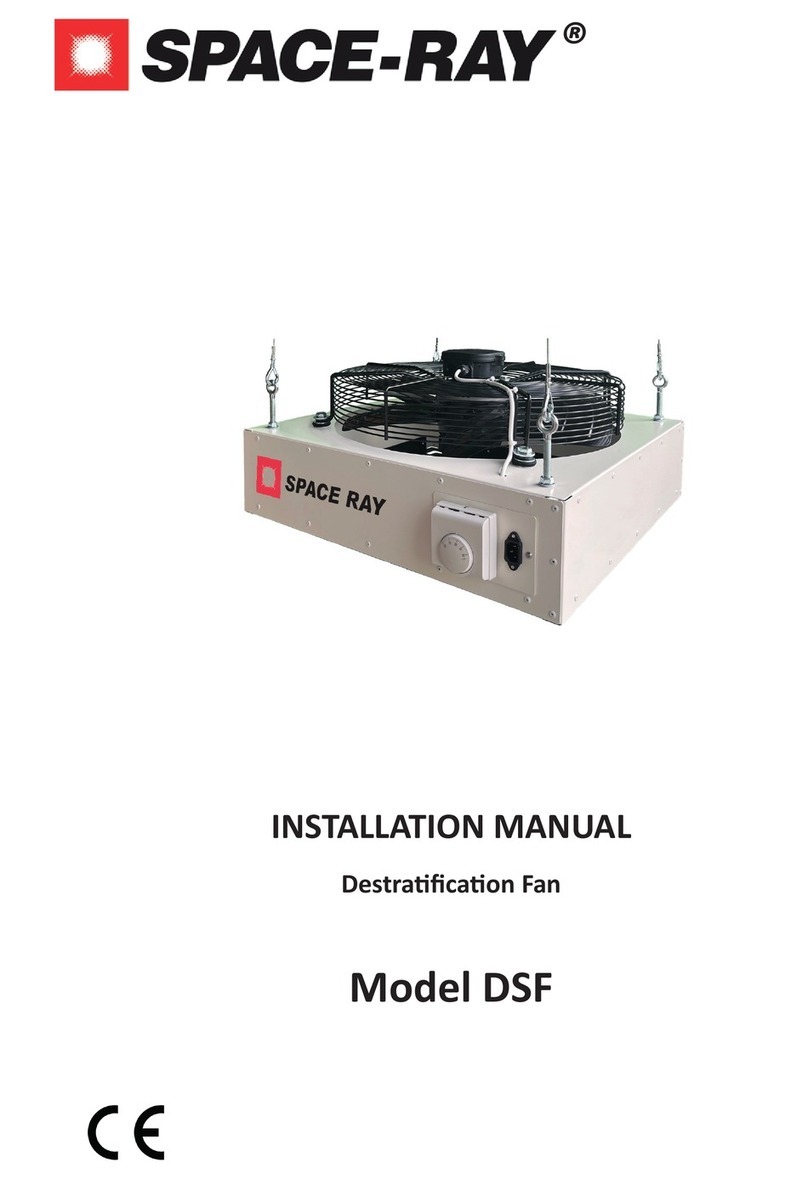
The SD destracaon fan consists of a metal casing with
a bladed fan & motor ed within a fan guard. There is an
outlet grille with adjustable louvers on the opposite side,
which enables the airow to be directed in the desired
direcon. A ed thermostat allows automac operaon.
The SD destracaon fan is designed to be ed within
the roof space of a building to recirculate e soluon to
achieving this is by ng destracaon fans. These fans
recirculate the, otherwise wasted, warm air gathering
within the roof space, to low level. The ed thermostat
(SD models) automates this process.
i.e If the room thermostat is set at 25°C, it will switch the
fan on as soon as this temperature is achieved at ceiling/
roof level. The fan will stop when the thermostat detects
a reducon in temperature of approx 1.5°C. The fan speed
can be controlled by an oponal 5-stage switch. This
switch also has a stage that cuts-o power to the installa-
on (stage 0).
The installaon of a correctly sized destracaon
system, pays for itself quickly due to the signicant en-
ergy savings achieved All SD models are available with an
EC motor, which reduces the electricity consumpon by
up to 25%.
This appliance may only be installed and maintaind by a
qualied and competent person.
• The minimum suspension height is 2.7meters. That
is because of safety reasons on touching rotang
parts.
• Disconnect the appliance from the power supply
before performing maintenance on this appliance.
• Cauon, this appliance can start automacally!
• Take care of a safe area when working on this
appliance
• Use cered access equipment.
• Take care of your personal safety. Use safety
gloves and safety shoes.
• This fan can be used by children aged 8 years and
above and by persons with reduced physical, sen-
sory or mental capabilies or lack of experience
and knowledge, if they are supervised or instructed
concerning use of the appliance in a safe way and
understand the hazards involved.
• Children may not play with the fan.
• Children may not clean and maintain this fan with-
out supervision.
Operaon/installaon of appliances not in accordance
with this manual will render warranty void. It is not per-
mied to change the specicaons or to make modica-
ons of any kind, to this appliance.
SD3 SD5 SD7 SD10
3 3,200 5,600 7,000 10,000
350 450 500 630
0.35 0.45 0.50 0.65
5 to 8 7 to 10 8 to 12 12 to 15
230V 1 Phase N & E - 50Hz
155 290 400 480
0.75 1.3 1.85 2.1
1380 1360 1315 1000
33 to 56 35 to 59 37 to 59 47 to 61
11 18 18 43

2.2 Dimensional data
• The products used for suspension should be t for
purpose.
• The minimum suspension height is 2.7m. .
• Install the appliance with 2 persons, keep in mind,
working on height and the weight of the appliance.
• Take care of a safe area when working on this ap-
pliance
• Use cered access equipment.
• Take care of your personal safety. Use safety
gloves and safety shoes.
The unit has been applied with 4 suspension eyes for use
with chains or steel wire (not included). Ensure the appli-
ance has an uninterrupted supply of air on both inlet &
outlet, a minimum clearance around the air inlet of 0.5m
should be observed. For exact distance for each specic
unit consult the technical data.
A rule of thumb, choose one fan per 300m2 oor surface.
A more accurate method is on basis of circulaon short-
age.
This is easy to calculate:
Calculate the volume of the space in m3, mulply this by 2.
The resulng gure is the volume in m3/h needed by the
SD destracaon fans.
Select the SD model based upon air output, throw of the
unit and height of the room. Then simply take the calu-
lated air volume and divide by the air volume produced
by your selected SD model. The resulng gure is the qty
needed for your applicaon.
Selecng an SD model with the highest air vol-
ume is not nessecarily the best soluon. It is important
to achieve uniform air distribuon throughout the space,
for maximum comfort and reduced running costs.
Occasionally it will be nessecary to install more SD fans
that calculaons indicate to achieve uniform air distri-
buon. In these scenarios, where possible, reduce the
model size and increase the quanty.
Always ensure the model of fan is capable of
being installed at the height you propose.
Posion the destracaon fan preferably towards the
end of the throw or area that is not directly served by the
heaters throw.
In general, a higher number of fans provides beer air dis-
tribuon.
We suggest that one fan is used per 150 to 300m2 square
of oor surface, taking into account mounng height and
model.
Each SD fan should be ed approx. 1.0m beneath the
roof or ceiling, but not closer than 0.35m. The distance
between oor and fan may not exceed the length of the
fan’s throw as this will prevent the warm air from reaching
the low level. Ensure that the fan is not mounted lower
than the minimum throw to avoid dras and oor dust
from being disturbed.
Even with the louvres set at maximum deecon, there
will be a severe dra when the unit is suspended too low.
Do not place the SD fans above plant machinery or high
obstacles.
Fig.1 SD Destracaon fan main components
A
C
E
A. Fan & motor assembly
B. Suspension eyebolts x 4
C. Thermostat
D. Outlet louvre frame assembly
D
SD3 SD5 SD7 SD10
470 600 600 800
470 600 600 800
289 319 328 438
340 375 375 740
A
A
NOTE
IMPORTANT

Locaon examples:
Before starng installaon ensure that the
electrical circuit you are working on has been shut o.
The appliance must be earthed!
The installaon must comply with all applicable local and/
or naonal standards i.e. NEN 1010.
There should be a suitable electrical circuit with a main
fuse. There is an electrical diagram further on in this guide.
The power supply is 230Vac (50 Hz) with earth.
The fan must to be equipped with a 230Volt isolaon
switch or power plug. This switch should disconnect phase
and neutral (not earth) and have a 3mm contact opening
at least. Switches or power plugs must be accessible at all
mes. For power supply, the fan has been provided with a
3-pole power plug (female). The installer should connect
a 3-wire mains cable and a power plug to it.
The SD fan is provided with a 230 Volt thermostat (unless
requested otherwise).
Once the installer has connected the unit to the mains
electrical supply (see paragraph 4.2) it is ready for use.
The ed thermostat should be set to the temperature at
which the fan is required to be switched on (typically 4 to
7OC above ambient set-point). Read paragraph 5.1 for a
correct temperature seng.
When the user wishes to control the fan speed, a 5-stage
switch can be added to the installaon. This switch can
transform the current to the fan motor in stages.
The 5-stage speed control is connected to the
power supply of the SD fan. Depending upon the chosen
stage, the fan will run fast or slowly.
Before installaon also consult the manual for the 5 stage
switch. See chapter 11, diagram 2.
Before starng maintenance make sure that
the electrical circuit you are working on has been isolat-
ed.
The appliance must be earthed.
Set the thermostat of the SD unit approx. 4 to 7°C above
the ambient temperature desired at 1.5m above oor
level. The smaller the dierence between the room ther-
mostat seng and that of the SD destracaon fan, the
longer the unit will be operave.
The SD does not need manual control, it is automac.
Generally temperature seng has to be done by
the installer. The user is allowed to do following sengs:
• Set the temperature at which the fan should ven-
late.
• Turn ON/OFF main switch
• Change fan speed by selecng one of the 5 stages
on the 5-stages switch.
Aenon: Do not set the louvres at an angle greater
than 20°. This will reduce the air volume and in turn the
throw.
In areas where heavy dust is present, it may be necessary
to clean the fan & guard with compressed air once a year.
If the guard is covered with severe dust, the fan will not
provide opmal performance.
Check if the appliance turns ON and OFF as it should on
the thermostat.
Pay aenon on:
• The ON and OFF switching from the thermostat
• The smooth rotaon of the fan
• Remove the dust from the appliance
• Check that the fan does not have severe vibraon
because of unbalance on the fan blades
WARNING!
WARNING!
ATTENTION!

L N E

L N E
17INSTALLATION MANUAL AIR HEATER TYPE EH
11 Disposal and recycling
The meaning of the symbol on the material, its accessory or packaging indicates that this
product shall not be treated as regular waste. Please, dispose of this equipment at your
applicable collection point for the recycling of electrical and electronic equipments waste.
In the European Union and Other European countries which there are separate collection
systems for used electrical and electronic product. By ensuring the correct disposal of this
product, you will help prevent potentially hazardous to the environment and to human health,
which could otherwise be caused by unsuitable waste handling of this product. The recycling
of materials will help conserve natural resources. Please do not therefore dispose of your old
electrical and electronic equipment with your regular waste.
12 Declaration of conformity
Winterwarm Heating Solutions B.V.
Industrieweg 8
7102 DZ, Winterswijk
The Netherlands
Declares that air heater types:
• EH5, EH10, EH15, EH20, EH25, EH30 & EH40
Are in accordance with the essential requirements of the relevant EU directives, being:
• 2014/35/EU (LVD) relating to the electric safety of appliances
• 2014/30/EU (EMC) relating to electromagnetic compatibility of appliances
• 2006/42/EG (MD) relating to the safety of machinery
Goods should be installed and used in accordance with our instructions and with the applicable local and international rules.
Installation should be done by an authorized, qualified and competent installer.
Winterswijk, December 15th 2020
Ir. M. Fiselier
Director Operations
We hereby declare that our products sasfy the applicable European direcves, decisions
and regulaons, as well as the requirements stated in the referenced standards.

FACTORIES: IPSWICH, ENGLAND - CHARLOTTE, N.C, U.S.A
Gas Fired Products (UK) Ltd
Chapel Lane
Claydon
Ipswich
Suolk, IP6 0JL
Tel: +44(0)1473 830 551
Fax: +44(0)1473 832055
www.spaceray.co.uk
info@spaceray.co.uk
®
SD Manual May 2023
Table of contents
Other Space-Ray Fan manuals
