Space-Ray DSF20 User manual
®
INSTALLATION MANUAL

This user’s guide is meant for the installer and if necessary
for the user. It’s a reference to operaon and installaon
of the DSF range of destracaon fans.
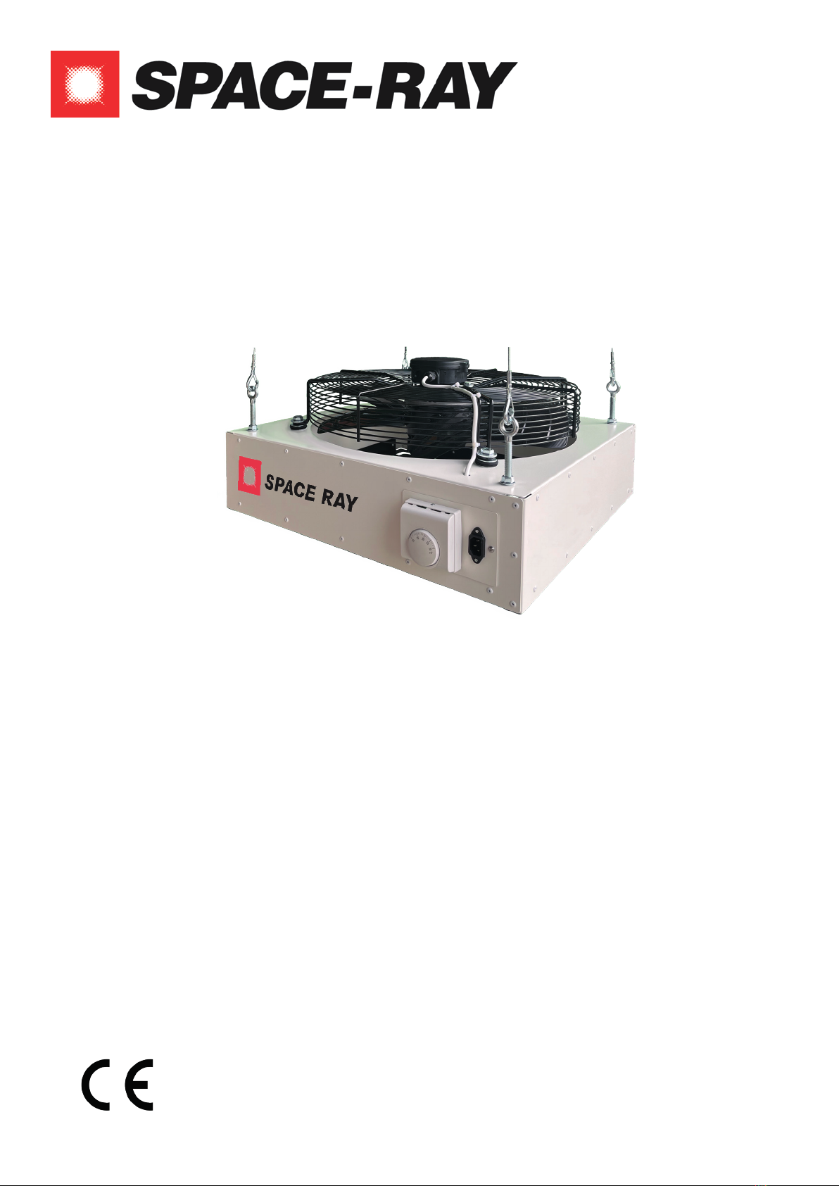
The DSF destracaon fan consists of a metal casing with
a bladed fan & motor ed within a fan guard. There is an
outlet with pressed louvers on the opposite side, which
enables the airow to be directed in the desired direcon.
A ed thermostat allows automac operaon.
The DSF destracaon fan is designed to be ed within
the roof space of a building to recirculate otherwise wast-
ed, warm air gathering within the roof space, to low level.
The ed thermostat automates this process.
i.e If the room thermostat is set at 25°C, it will switch the
fan on as soon as this temperature is achieved at ceiling/
roof level. The fan will stop when the thermostat detects
a reducon in temperature of approx 1.5°C.
The installaon of a correctly sized destracaon
system, pays for itself quickly due to the signicant energy
savings achieved
• The minimum suspension height is model depen-
dane, please check the technical data table below.
• Disconnect the appliance from the power supply
before performing maintenance on this appliance.
• Cauon, this appliance can start automacally!
• Take care of a safe area when working on this
appliance
• Use cered access equipment.
• Take care of your personal safety. Use safety
gloves and safety shoes.
Operaon/installaon of appliances not in accordance
with this manual will render warranty void. It is not per-
1. General 2
1.1 Descripon 2
1.2 Funcon 2
1.3 Warnings 2
1.4 Warranty 2
2. Technical Data 3
2.1 Dimensional data 3
3. Installaon 3
3 2450 3955 6800 8510 9700 11435
9 10 12 14 18 20
46789 10
230V 1 Phase N & E - 50Hz
1.9 2.4 4.8 6.8 6.6 10.6
0.65 0.82 1.7 2.4 2.35 3.75
49 50 50 53 55 58
12 13 16 21 25 25
A606 606 606 744 744 744
606 606 606 744 744 744
C532 532 532 652 652 652
D532 532 532 652 652 652
E260 260 260 300 300 300
155 155 155 175 175 175
C
A
E
3.1 Suspension 3
3.2 Calculang number of fans required 3
3.3 Posioning 3
4. Electrical Connecons 3
4.1 230VacSupply 3
5. Electrical Connecons 3
5.1 Operaon 3
5.2 Maintenance 3

mied to change the specicaons or to make modica-
ons of any kind, to this appliance.
• The method/products used to suspend the unit
must be t for the purpose.
• The minimum suspension height is 4.0m. .
• Install the unit with 2 persons, keeping in mind,
working at height and the weight of the unit.
• Take care and assign a safe area when working on
this appliance
• Use cered access equipment.
• Take care of personal safety. Use safety
gloves and safety shoes.
Each unit has been ed with 4 suspension eyes for use
with chains or steel wire (not included). Ensure the appli-
ance has an uninterrupted supply of air on both inlet &
outlet, a minimum clearance around the air inlet of 0.5m
should be observed.
Calculate the volume of the space in m3, mulply this by 2.
The resulng gure is the volume in m3/h needed by the
DSF destracaon fans.
Select the DSF model based upon air output, throw of the
unit and height of the room. Then simply take the calulat-
ed air volume and divide by the air volume produced by
your selected DSF model. The resulng gure is the qty
needed for your applicaon.
Selecng a DSF model with the highest air volume
is not nessecarily the best soluon. It is important to
achieve uniform air distribuon throughout the space,
for maximum comfort and reduced running costs.
Occasionally it will be nessecary to install more DSF fans
that calculaons indicate to achieve uniform air distri-
buon. In these scenarios, where possible, reduce the
model size and increase the quanty.
Always ensure the model of fan is capable of
being installed at the height you propose.
Posion the destracaon fan preferably towards the
end of the throw or area that is not directly served by the
heaters throw.
In general, a higher number of fans provides beer air dis-
tribuon.
Each DSF fan should be ed approx. 1.0m beneath the
roof or ceiling, but not closer than 0.5m. The distance be-
tween oor and fan may not exceed the distance stated in
the technical data as this will prevent the warm air from
reaching low level.
On the outlet of the DSF units are a series of twist and set
outlet louvres. It is essenal that these louvres be opened
before the fan unit is switched on for the rst me.
The louvres are intended to ensure that the airow from
the fan unit is correctly distributed. Each louvre should be
opened to an angle of at least 45O. Even with the louvres
set at maximum deecon, there will be a severe dra
when the unit is suspended too low.
Before starng installaon ensure that the
electrical circuit you are working on has been shut o.
This appliance must be earthed!
The installaon must comply with all applicable local and/
or naonal standards.
All DSF units are supplied fully wired and come with
a plug-in 2m ying lead. This should be connected to a
fused mains isolator (locally mounted).
The ed thermostat should be set to the temperature at
which the fan is required to be switched on (typically 2 to
5OC above ambient set-point).
Before starng maintenance make sure that
the electrical circuit you are working on has been isolat-
ed.
The appliance must be earthed.
The DSF unit does not need manual control, it is automat-
ic. Generally temperature seng has to be done by
the installer.
The user is allowed to do following sengs:
• Set the temperature at which the fan should ven-
late.
• Turn ON/OFF main switch
In areas where heavy dust is present, it may be necessary
to clean the fan & guard with compressed air once a year.
If the guard is covered with severe dust, the fan will not
provide opmal performance.
Check if the appliance turns ON and OFF as it should on
the thermostat.
Pay aenon on:
• The ON and OFF switching from the thermostat
• The smooth rotaon of the fan
• Remove any dust from the appliance
• Check that the fan does not have severe vibraon
because of unbalance on the fan blades
NOTE
IMPORTANT
WARNING!
WARNING!

FACTORIES: IPSWICH, ENGLAND - CHARLOTTE, N.C, U.S.A
Gas Fired Products (UK) Ltd
Chapel Lane
Claydon
Ipswich
Suolk, IP6 0JL
Tel: +44(0)1473 830 551
www.spaceray.co.uk
info@spaceray.co.uk
®
DSF Manual Nov 2023
This manual suits for next models
5
Other Space-Ray Fan manuals


Popular Fan manuals by other brands

Princess
Princess 352526 Instructions for use

Fanimation
Fanimation Brewmaster FP10 Series owner's manual

Vents-us
Vents-us VKM EC 100 installation guide

Xpelair
Xpelair GX12 Installation and operating instructions

Craftmade
Craftmade Jamison JAM52 installation guide

Maico
Maico WS 320 Series quick start guide


Kampmann
Kampmann Venkon Series Assembly, installation and operating instructions

Meltem
Meltem M-WRG-II M-U2 installation manual

Westinghouse
Westinghouse Saynet-EI-Deacon-WH20 owner's manual

CLIVET
CLIVET CFW-2 1-5 Manual for installation, use and maintenance

NuAire
NuAire FLAT2000 L installation manual

Chicago Electric
Chicago Electric 66878 Set up and operating instructions