Space-Ray SR User manual
®
INSTALLATION MANUAL

1. General 3
1.1 Descripon 3
2. Technical Data 3
3. Pre-Installaon 3
3.1 Locaon 3
3.2 Contents of the package 3
4. Installaon 3
4.1 Fixing the ceiling J-hook 3
4.2 Fing the fan blades 3
4.3 Hanging the fan 4
4.4 Wiring the fan 4
4.5 Fing the safety wire 4
4.6 Fing the upper canopy 4
5. Troubleshoong 5
6. Maintainance 5
17INSTALLATION MANUAL AIR HEATER TYPE EH
11 Disposal and recycling
The meaning of the symbol on the material, its accessory or packaging indicates that this
product shall not be treated as regular waste. Please, dispose of this equipment at your
applicable collection point for the recycling of electrical and electronic equipments waste.
In the European Union and Other European countries which there are separate collection
systems for used electrical and electronic product. By ensuring the correct disposal of this
product, you will help prevent potentially hazardous to the environment and to human health,
which could otherwise be caused by unsuitable waste handling of this product. The recycling
of materials will help conserve natural resources. Please do not therefore dispose of your old
electrical and electronic equipment with your regular waste.
12 Declaration of conformity
Winterwarm Heating Solutions B.V.
Industrieweg 8
7102 DZ, Winterswijk
The Netherlands
Declares that air heater types:
• EH5, EH10, EH15, EH20, EH25, EH30 & EH40
Are in accordance with the essential requirements of the relevant EU directives, being:
• 2014/35/EU (LVD) relating to the electric safety of appliances
• 2014/30/EU (EMC) relating to electromagnetic compatibility of appliances
• 2006/42/EG (MD) relating to the safety of machinery
Goods should be installed and used in accordance with our instructions and with the applicable local and international rules.
Installation should be done by an authorized, qualified and competent installer.
Winterswijk, December 15th 2020
Ir. M. Fiselier
Director Operations
This product and the packaging are made of valueable raw materials and should not be disposed
in the household waste.
Sort the dierent kinds of waste of the packaging and the appliance and follow the current
disposal regulaons
Ensure that authorised disposal and recycling methods are used.
This user’s guide is meant for the installer and if necessary
for the user. It’s a reference to operaon and installaon
of the SR destracaon fan.
SD is a 3 bladed ‘sweep’ style fan designed to reduce
energy use by recirculang warm air gathered at high
level, to low level where it will be more benecial.
Operaon of the SD fan is via a wall on/o switch (by
others), an oponal speed controller is available.
Ensure that the ceiling/structure is sucient to support at
least 50kg/m² moving weight.
Choose a locaon where there is no risk to personnel or
objects coming into contact with the rotang blades.
Ensure that a minimum mounng height of 2.5m above
oor level is maintained.
Ensure the space is damp free and does not contain
ammable, explosive substances or gases.
Follow the requirements of automac re alarm systems
to ensure the fan is not able to operate when the re
alarm is triggered.
For the installaon of the ceiling J-hook use only fasten-
ings suitable for this kind of ceiling. The choice of the
fastening and the correct installaon of the J-hook is the
responsibility of the installer.
Verify the power supply is compable with the fan rang
label and is protected by a fused isolator, with double
terminal and contact openings at least 3mm.
Check the package contains all the components:-
1No Motor, assembled with downrod, rubber
grommet and canopies
3No Fan blades
1No Ceiling J-hook with safety pin
2No Screws to x the upper canopy
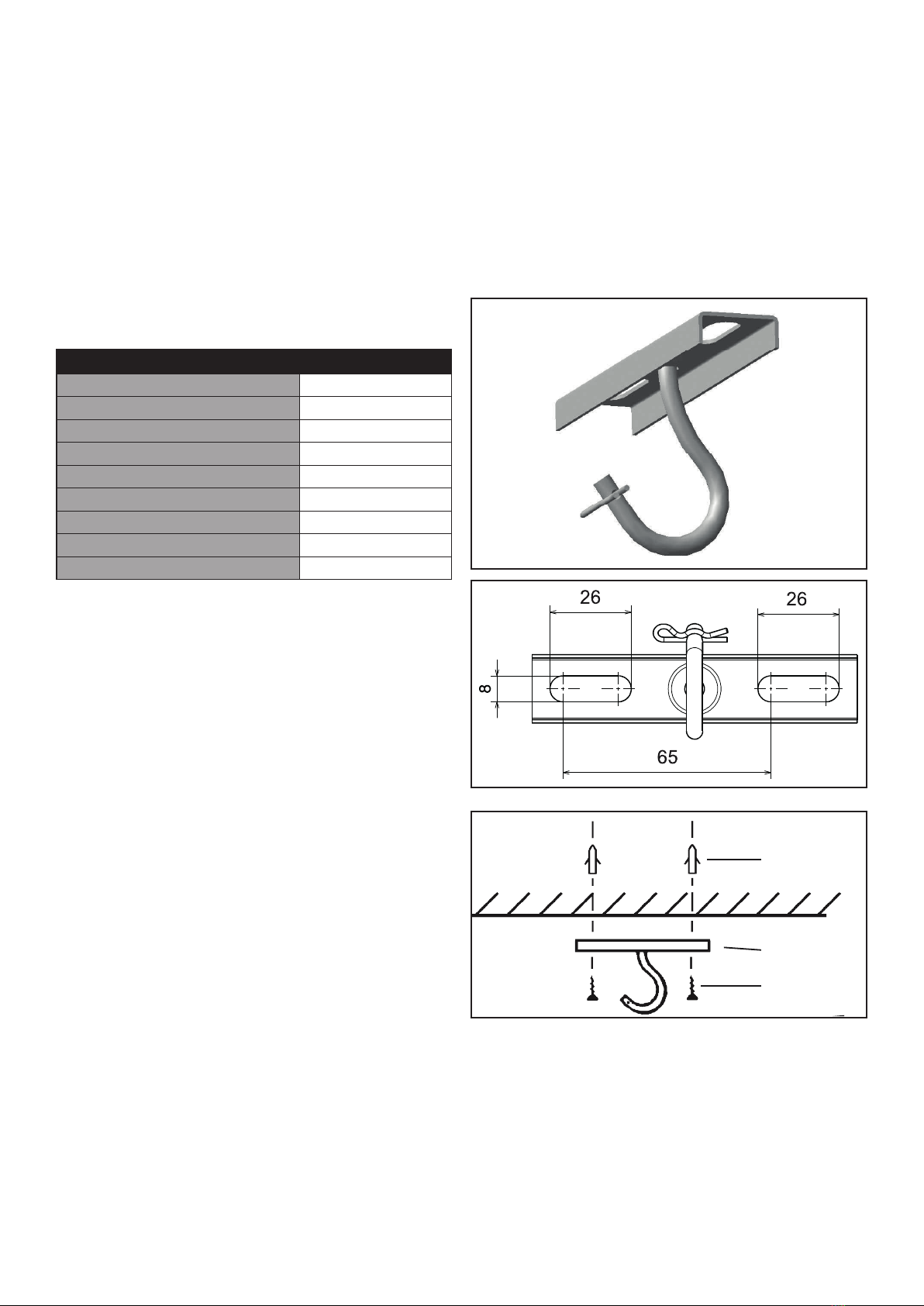
Mount the ceiling J-hook (Fig. 3) with xings suitable for
the type of ceiling. Enure all screws are ghtened well.
The J-hook must be rmly xed and capable of support-
ing at least 50kg of moving weight and must not gradually
work loose due to the movement of the fan when in use.
Using a at surface, suitably protected to prevent
scratching the motor or blades, posion the motor ready
to aach the fan blades.
The fan blades are balanced to prevent the motor from
wobbling, therefore DO NOT (or exchange with another
fan) t in any other posion than the one indicated on the
fan blade.
Table 1 - Technical data
15,000m3/h
10m
1420mm
52dB(A)
230V 50Hz
0.35A
9.5kg
690x255x235mm
Black or white Fig. 1
Fig. 2
Ceiling xings
(by others)
J-Hook
Fixing screws
(by others)
Fig. 3
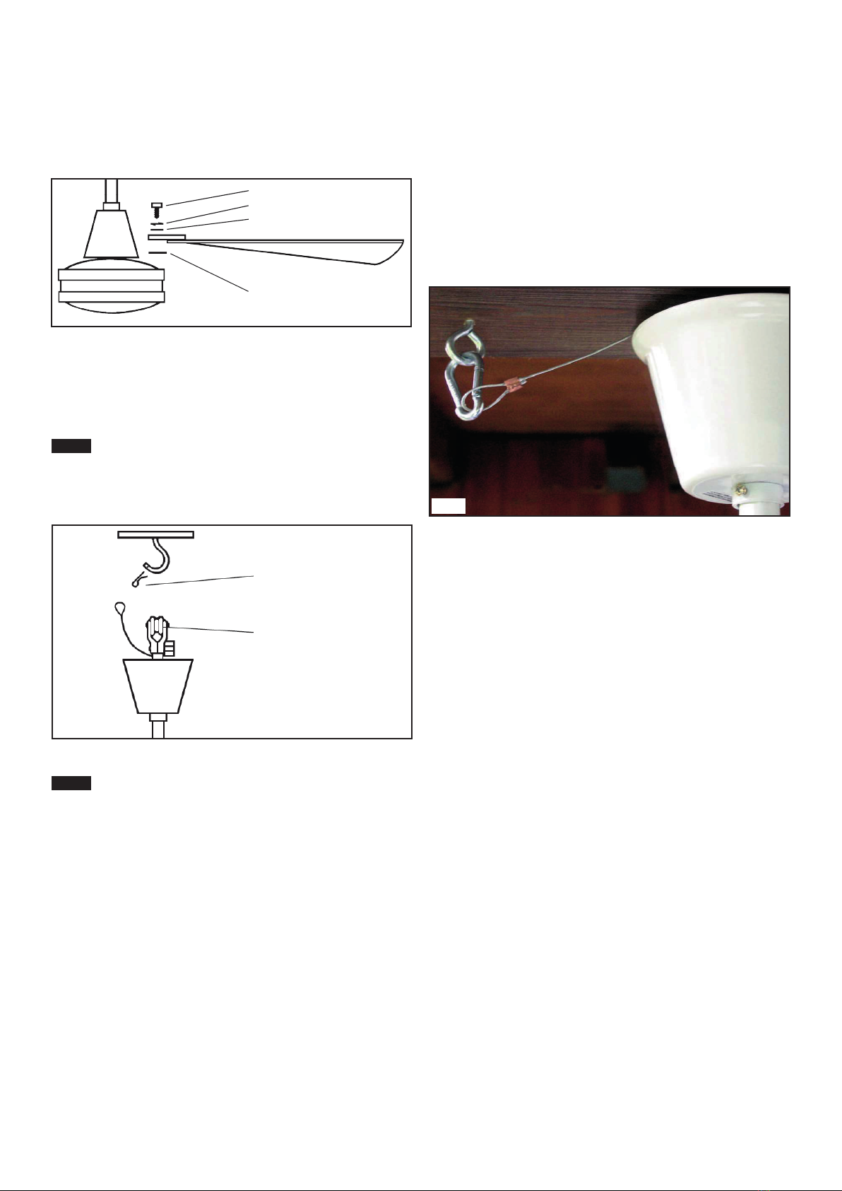
Mount the three fan blades (blade holder up) to the mo-
tor using the screws, spring washers, washers and blade
holder underlay cards. See Fig. 4).
Ensure the blade screws are evenly and safely ghtened
(with care not to damage the thread).
Carefully hang the fan assembly by placing the rubber
grommet in the ceiling J-hook, ensuring not to trap wires
between the rubber grommet and the ceiling J-hook.
Place the safety pin in the hole at the end of the
ceiling J-hook. The fan must not be used without the
original J-hook safety pin. If the pin is lost, order a new
one.
The electrical installaon and any repairs must be
carried out by a qualied electrician, in accordance with
all local and naonal standards currently in force.
Before commencing any electrical work, ensure the
power supply is isolated and tagged to prevent acciden-
tal operaon.
Connect the three wires from the power supply to the
fan terminals as follows:
Green/yellow wire with the “Earth”
Blue wire with the “Neutral”
Brown wire with the “Line”
Ensure that the wiring is long enough to allow for a lile
movement of the fan - wires MUST NOT be installed taut.
For wiring of the oponal fan controller, follow the
instrucons packed with the controller.
This appliance MUST be earthed.
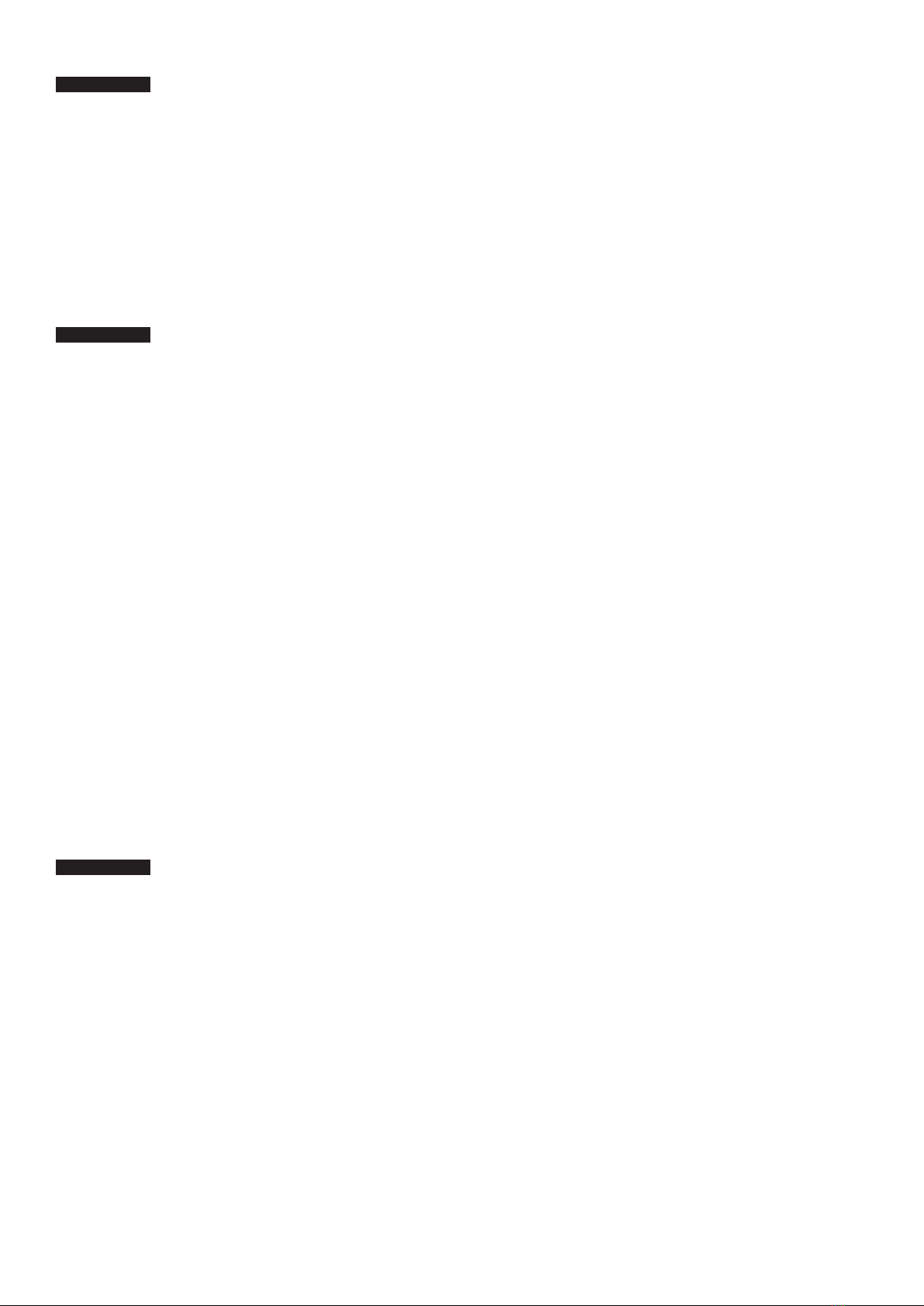
Choose a screw or screw eye, suitable for the safety wire
and the type of ceiling into which it will be xed. - Fix the
safety wire with the screw or, the screw eye to the ceil-
ing, 100mm to the side of the upper canopy. Ensure the
safety wire does not touch the J-hook, the rubber grom-
met or the terminal. The wire MUST NOT be stretched.
See Fig. 6 - carabiner not included.
The screw or screw eye must be immovable and capable
able to support at least 50 kg moving weight and hold
the safety wire securely.
Raise the upper canopy to the ceiling. Make sure there
is 10mm distance between the ceiling and the top of the
upper canopy. Now x the upper canopy in place with
the two screws (do not over-ghten).
NOTE
Fig. 4
Blade screw
Spring washer
Washer
Blade underlay card
NOTE
Fig. 5
Safety pin
Rubber grommet
Fig. 6
Before checking the fan, make sure the
main power supply is switched o. The motor
housing must not be opened.
Suggested remedy
• Check main and branch circuit fuses or circuit
breakers.
• Check line wire connecons to fan and switch wire
connecons in switch housing.
IMPORTANT: For safety reasons, the fan must not be
operated if it produces unusual noises outside of its
inial installaon!
Suggested remedy
• Allow a “running-in” period of 24 hours. Most
noises, associated with a new fan, will disappear
aer this period.
• While tesng the motor without blades, a reso-
nance sound can happen, this is normal. When
blades are ed, this sound will cease.
• Check the screws which aach the fan blade to the
motor to make sure that they are ght.
• Check all nuts and bolts behind the two canopies
for perfect ghtness.
• Check the upper canopy has 10mm clearance to
the ceiling. The upper canopy should not touch the
ceiling or power cables.
• Check the lower canopy, coer pin and wires
under the lower canopy. These parts should not be
touching the motor.
• A slight humming sound if used with the oponal
speed controller (especially on lower speed) is
normal for all ceiling fans. Use our oponal speed
control avoid or minimize this sound.
- IMPORTAN For the reason of safety and the risk of
damage the fan must not be used when it is seriously
wobbling!
Suggested remedy
• A lile wobbling, especially aer start-up or aer
speed changes, is normal. Once end speed is
reached, the fan will be become stable.
• Main causes for wobbling are unequal blades. If
one blade is damaged or bent use a complete new
set of three blades.
• The fan blades are balanced by weight to prevent
wobbling. If you have to assemble a range of fans,
be sure not to exchange a blade from another set
of three blades.
• Check to make sure the fan blade screws which
aach the fan blade to the motor are ght.
• Check all nuts and bolts under the two canopies
for perfect ghtness.
Suggested remedy
• The capacitor could be damaged, this may be due
to overload or a power spike. A qualied electrician
should check the capacitor and replace if nessecary.
Maintenance is essenal to ensure the correct operaon
of the fan. This should only be carried out by a suitable
qualied professional.
Before commencing with any maintenance and/or clean-
ing of the fan, ensure the power is isolated.
Over me some connecons/xing may start to work
loose, therefore all connecons must be checked at least
twice a year for perfect ghtness. Especially the blade
screws, all nuts, bolts and coer pins inside the two
canopies, the pin and strength of the ceiling J-hook and
the safety wire.
In case of intensive use the above checks should be more
frequent.
If a damp cloth is needed for cleaning, do not use liquid
soap or aerosol cleaners.
Never dip the fan into water or other liquids.
IMPORTANT!
IMPORTANT!
IMPORTANT!

FACTORIES: IPSWICH, ENGLAND - CHARLOTTE, N.C, U.S.A
Gas Fired Products (UK) Ltd
Chapel Lane
Claydon
Ipswich
Suolk, IP6 0JL
Tel: +44(0)1473 830 551
Fax: +44(0)1473 832055
www.spaceray.co.uk
info@spaceray.co.uk
®
SR Manual August 23
Table of contents
Other Space-Ray Fan manuals


Popular Fan manuals by other brands

Xpelair
Xpelair GX9 and Installation and operating instructions

for Living
for Living 043-7021-6 instruction manual

Vents
Vents 100 Quiet-dMEV DC user manual

NuAire
NuAire HPKF Installation and Maintenance

DYNABREEZE
DYNABREEZE FA-26243 Instructions & user's manual

Nuaire Group
Nuaire Group MRXBOX95B-LP1 Installation and Maintenance


