Spacek SD-1 Minisport TG Owner's manual
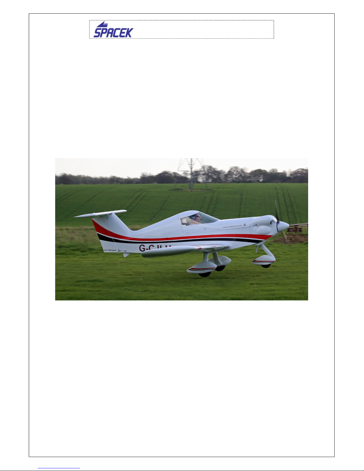
SD-1 Minisport TG, SE-33, P.O.H
1
Issue 1
PILOT OPERATING HANDBOOK (P.O.H)
FAI UL / SSDR
SD-1 MINISPORT
Type: SD-1 Minisport TG, engine SE-33, propeller Helix H30F
Airplane must be operated in compliance with the information and limitations
stated in this manual.

SD-1 Minisport TG, SE-33, P.O.H
2
Issue 1
CONTENTS
1. General
1.1 Description of airplane
1.2 Warning, cautions notes
1.3. Description of airplane
1.4. Main technical data
1.5. Engine and propeller
1.6. Three-view airplane drawing
2. Operation Limitations
2.1 Airspeed Limits
2.1.2 Air speed indicator marking
2.1.3 Limitation of maximal permitted wind speed
2.1.4 Engine limitation
2.2. Weights
2.3. Loads
2.4. Approved maneuvers
2.5. G-forces
2.6. Other limitations
2.7. Limitations labels
3. Operation data and procedures
3.1 Emergency procedures
3.1.2. Engine failure
3.1.3. Smoke and fire
3.1.4. Emergency and safety landing
3.1.5. Recovery of unintentional spin
4. Normal procedures
4.1. Assembling and Disassembling
4.2 Pre-flight Check
4.3. General procedures and check list
4.3.1 Prior to engine starting
4.3.2 Engine warming, ground test
4.3.3 Taxying
4.3.4 Pre-flight Check
5. Performance
5.1 Take-off distance
5.2 Landing distance
5.3 Climb
5.4 Airspeed
5.5 Glide
5.6 Stall speeds
5.7 Airspeed Indicator Calibration System
SD-1 Minisport TG, SE-33, P.O.H
3
Issue 1
1. General
The airplane SD-1 Minisport belongs to the FAI-UL category, according to the CAA
UK as Single Seat Deregulated microlight (SSDR).
1.1. Important information
Attention!
This product is not liable to be approved by Civil Aviation Authority, and it
is operated at someone’s own risk. Intentional spins, stalls and aerobatic
maneuvers are prohibited.
‘Every damage of airplane must be reported to an approved inspector – technician.
He will recommend the way how repair the damage and then he will provide the
check and technical inspection. In the airplane documentation there must be made a
report about the case’
1.2. Warnings, cautions, notes
The following information applies to warnings, cautions and notes used in the
Flight manual:
WARNING
MEANS THAT NON-OBSERVATIONS OF THE
CORRESPONDING PROCEDURE LEADS TO AN IMMEDIATE
OR IMPORTANT DEGRADATION OF FLIGHT SAFETY.
CAUTION
MEANS THAT NON-OBSERVATIONS OF THE
CORRESPONDING PROCEDURE LEADS TO A MINOR OR
TO A MORE OR LESS LONG TERM DEGRADATION OF THE
FLIGHT SAFETY.
NOTE
Draws the attention to any special item not directly related to
safety but which is important or unusual.
1.3 Description of airplane
The SD-1 Minisport is an ultra-light aerodynamically controlled, low-wing cantilever
single seat monoplane of mixed wood-composite construction, equipped with front
placed engine and fixed undercarriage of taildragger or tri-gear type. The airplane
could be equipped with parachute emergency system.
The airplane is designed according to the LTF-UL and UL-2 regulations, and is
intended for recreational flying in VFR.
SD-1 Minisport TG, SE-33, P.O.H
4
Issue 1
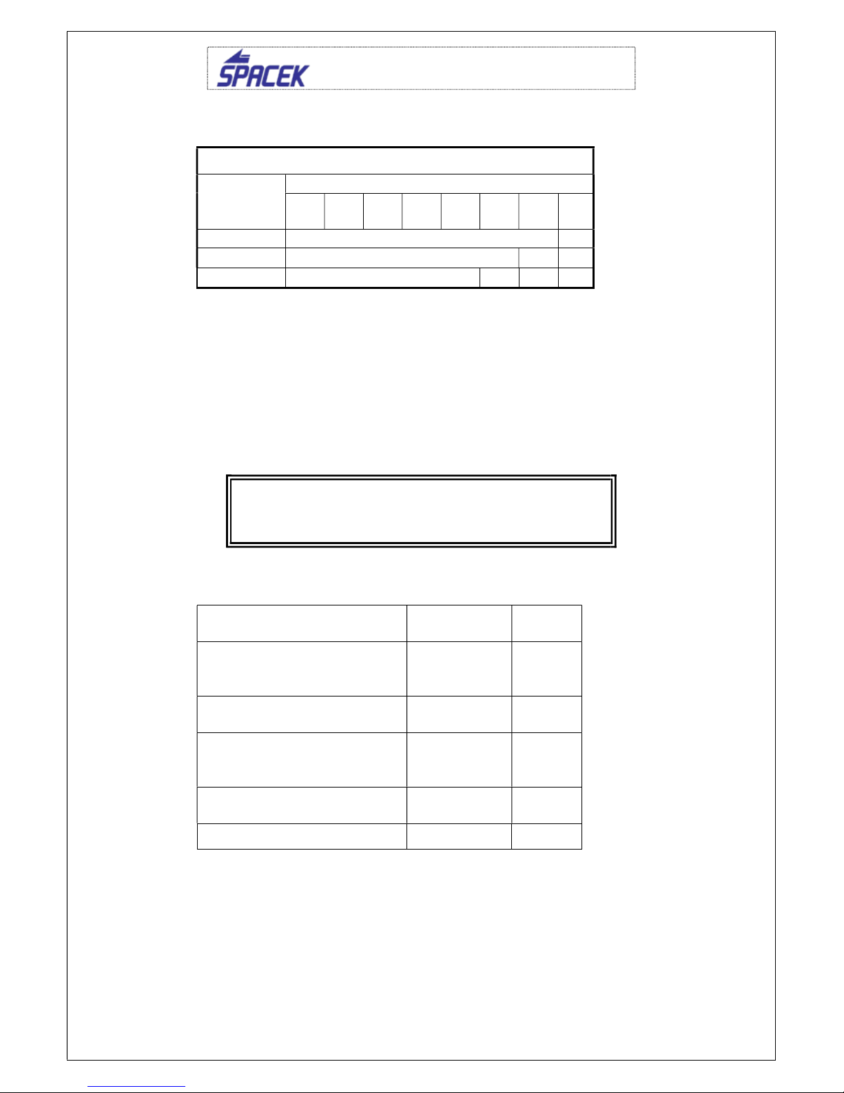
1.4 Main technical data
Measurements
Wing span…...…………………...… ..5,98 m
Fuselage length..………………….. ..4,35 m
Wing area .………………………….. ..6,1 m2
Wing aspect ratio…..…………….… ..5,85
MAC depth bmac………………………1,05 m
Horizontal tail unit span……..………1,96 m
Elevator Area…………………………0,95 m
Vertical tail Area……………………...0,44 m2
Landing gear gauge………………….2,78 m
Wheelbase…………………………….1,08 m
Main landing gear wheel diameter….0,3 m
Diameter of tail wheel………………..0,1 m
Propeller diameter……………………1,2 m
Weight
Empty weight………………………….(118-137) kg
Weight of a wing half ……………..……12 kg
Elevator weight…………………………..3 kg
Maximum take-off weight…………….240 kg
Payload…………………………..........110 kg
Fuel tank volume……………….……….35 l
Unusable fuel volume………………….0,5 l
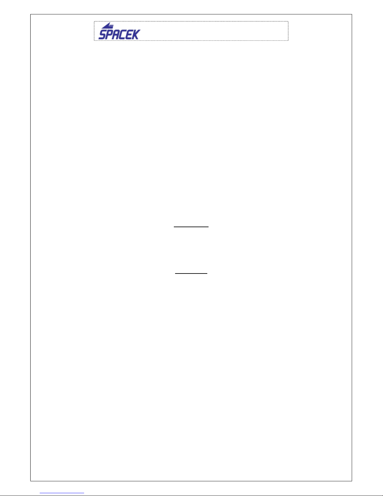
1.5 Engine and propeller
Engine
SE-33, simple V-twin OHV 4-stroke, air-cooled, direct drive, magneto ignition
Max. continuous power…………………25kW@3600 rpm
Max. take off power……………………..22kW@3100 rpm
Min. CHT…………………………………60°C
Max. CHT……………………………......240 °C
Min. oil temp……………………………..25 °C
Max. oil temp…………………………….140 °C
Oil. pressure……………………………..0,3-2,5 bar – indicated by red light
Oil. quantity………………………………cca 1,4l
Operating outside air temperature……..-10°C / +40°C
Fuel: MOGAS unleaded 98,95
Oil: API SG, SH, SJ, SAE 10W30
Propeller
Helix H30F 1,25 m L-ES-08-2
Typ: 2 blades composite, fixed pitch
Diameter: 1250 mm
Example for the engine monitor

SD-1 Minisport TG, SE-33, P.O.H
5
Issue 1
1.6 Three-view airplane drawing
1. Operation Limitation
2.1 Airspeed limitation
Speed IAS
(km/h)/(kt)
Meaning
VNE Never exceed speed 220 / 119
Do not exceed this speed in
any operation
VA Maximum maneuvering
speed 163 / 88
Do not make full or abrupt
control movement
above this
speed, because under certain
conditions the aircraft may be
overstressed by full control
movement.
V
FE
Maximum flap extended
speed 104 / 57
Do not exceed this speed with
the given flap setting.
SD-1 Minisport TG, SE-33, P.O.H
6
Issue 1
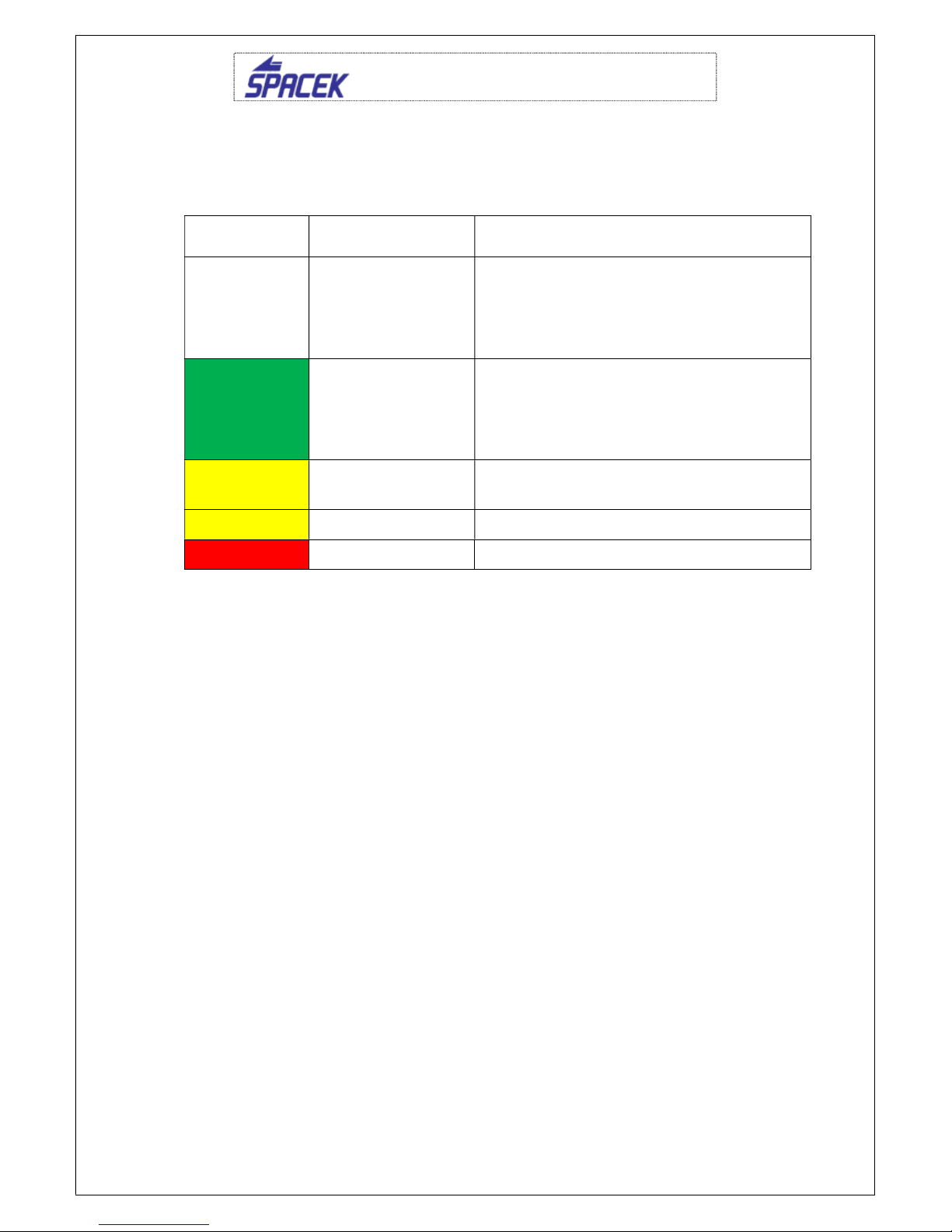
2.1.2 Airspeed indicator marking
Airspeed indicator markings and their color meanings are shown in the table
below:
Marking Value ( IAS )
Range (km/h)/(kt)
Meaning
White arc
64 – 104 / 34 – 57
Operation range with extended flaps.
(The lower limit is 1.1 VSO
in landing
configuration and m
aximum weight. The
upper limit is maximum permitted speed
with extended flaps.)
Green arc
78 – 163 / 46 – 88
Normal operation range. (The lower limit
is 1.1 VS1
when maximum weight,
maximum front position of C.G., and
retracted flaps. The upper limit is
maximum maneuvering speed V
A
.)
Yellow arc 163 – 220 / 88 –
119
Maneuvers must be conducted with
caution and only in smooth air
Yellow line 163 / 88 Maximum maneuvering speed Va
Red line 220 / 119 Maximum airspeed Vne
2.1.3 Limitation of maximum acceptable wind speed
The maximum acceptable wind speed for take-off and landing is 10 m/s (20kts).
The maximum acceptable perpendicular component of wind for take-off and
landing is 5 m/s (10kts).
2.1.4. Power plant limitation
Maximum allowable RPM 3600
Maximum continuous RPM 3600
Maximum CHT 220 ºC
Max. Oil Temp.: 140 °C
2.2. Weight
Maximum take-off weight...…………... 240 kg
Empty weight …………………….…… 130 kg
Approved centre of gravity positions:
Empty airplane C.G. position……......... 13÷18% MAC
Operating C.G. range………………….. 22
34% MAC
Minimum pilot weight………………… 61 kg
Maximum pilot weight………………... 105 kg
Maximum fuel weight……………….... 25 kg = 34 l
Maximum baggage weight……………. 10 kg
SD-1 Minisport TG, SE-33, P.O.H
7
Issue 1
2.3. Load
Maximum allowed filling of the fuel tank in liters
Weight of
baggage
(kg)
Pilot’s weight (kg)
55
60 65 70 75 80 95 10
5
0 Full fuel tank 7
5 Full fuel tank 21
10
Full fuel tank
21
14
2.4. Approved maneuvers
SD-1 is approved as FAI UL. Following maneuvers are approved to be performed:
Steep turns up to bank angle of 60
- recommended entering airspeed is 130
km/h(71kt).
Horizontal eights - recommended entering airspeed is 130 km/h (71 kt).
Climbing turns - recommended entering airspeed is 160 km/h (87 kt).
2.5. Maneuvering load factors
Maneuvering speed Airspeed
km/h / kt
Load
factor
VA- maneuver with maximum
deflection of a control
surface
163 / 88 + 4
VNE – maximum acceptable
airspeed 220 / 119 + 4
VA – maneuver with
maximum deflection of
a control surface
163 / 88 -2
VNE – maximum acceptable
airspeed 220 / 119 -2
VFE – with extended flaps 104 / 57 + 2
Warning
AEROBATICS AS WELL AS INTENTIONAL SPINS
ARE PROHIBITED!
SD-1 Minisport TG, SE-33, P.O.H
8
Issue 1
2.6. Other limitations
SMOKING IS PROHIBITED on the airplane board!
Heavy rain and very high humidity reduce aircraft performance!
In flight under these conditions is recommended to increase take-off and landing
speed by 5 knots.
2.7. Limitation labels
Airspeed IAS
Maximum airspeed VNE 220 km/h / 119 kt
Maximum maneuvering speed VA 163 km/h / 88 kt
Maximum flap extended speed VFE 104 km/h / 57 kt
AEROBATICS AS WELL AS INTENTIONAL SPINS
ARE PROHIBITED!
Flights according to IFR and intentional flights under icing
conditions are prohibited!
SD-1 Minisport TG, SE-33, P.O.H
9
Issue 1
3. Operation data and procedures
3.1 Emergency procedures
3.1.2 Engine failure
Engine failure at take-off below 50 m (150ft)
1. Adopt the glide airspeed to 110 km/h (59kt)
2. Choose an area for landing straight ahead, only in a case to prevent from
frontal crash change the direction
3. Ignition off
4. Fuel valve off
Engine failure during take-off when at least 50 m (150’) above ground
1. Correct the airspeed to 110 km/h (59kt)
2. Choose an area for landing straight forward in a free space without obstacles
3. Ignition off
4. Fuel valve off
5. Flaps for lift increasing according to your need
3.1.3 Smoke and fire
1. Fuel selector OFF
2. Throttle lever FULL
3. When the engine stops master switch OFF
4. Extinguish fire by slip. Do not start the engine again
5. Make a safety landing
3.1.4 Emergency and precautionary landing
Emergency landing
1. Airspeed adjust to 110 km/h (59kt)
2. Choose landing area – free space without obstacles
2. Tighten up the safety harness
3. Flaps – according to your need
4. Fuel selector OFF
5. Ignition OFF
6. Master switch OFF
Precautionary landing
1. Choose an area for landing – against the wind direction
2. In the altitude 50 m (150ft) above ground make a fly-over with extended small
flaps to check the chosen area for its surface and obstacles
3. In the altitude 150 m (500ft) above ground make circle with small flaps. Make
downwind checklist.
4. When lower visibility do not lost the chosen landing area from your view.
5. Approach for landing make in landing configuration with higher engine power.

SD-1 Minisport TG, SE-33, P.O.H
10
Issue 1
6. Correct the glide path to be able to touch-down immediately after flying over
the edge of chosen area.
7. After touch-down use brakes for prompt stop.
8. After stop shut off engine and master switch, close fuel valve and safe the
airplane.
3.1.5 Unintentional spin recovery
Standard procedure of recovery from spin:
1. Throttle lever - idle
2. Control stick - trim, ailerons – neutral position
3. Pedals - push down the pedal against the sense of rotation
4. Control stick - push forward and hold until rotation stops
5. Pedals - immediately after rotation stops return the
pedal from
deflection to the neutral position
6. Control stick - recover the diving by smooth pull back
4. Normal procedures
4.1 Assembly and disassembly
Before mounting clean easy removable hinges and struts. Lubricate them using
grease. Lubricate also hinges bushings placed in beams stubs and main horizontal
tail unit bracket. Push out auxiliary wings hinges and push on the right wing into the
fuselage tunnel. When the wing is enough close to the fuselage mount the linkage of
flaperon control handle to the flaperon stone, and the control handle into the flaperon
slot link. Fix up the auxiliary hinge and push on the main hinges into the stubs circa 1
cm deep using an extension stick. In the same way put the left wing on. Both wings
are on, push the main hinges in and fix them up by pins. Secure the auxiliary hinges
by binding wire.
When mounting the horizontal tail units (HTU), push the control link of trim surface
into the slot of HTU. Insert the hinge into the HTU bracket then insert the hinge
thorough fin bushing to the opposite bracket. Push pin into the hole in bracket of
HTU. Wrench a castle-nut on the pin and fix it up using a pin. Set the trim “heavy on
head” and joint the control link together with HTU by a bolt. Wrench a castle-nut and
secure it by a pin. Join the control link with the anti-servo trim lever and secure it by a
cotter pin.
4.2 Pre-flight check
Make the pre-flight check every flight day or before every first flight when assembled.
Incomplete or reckless check may cause an accident. Make the inspection in the way
described in the check list.
NOTE
Word "condition" in the procedures means visual check of surface for damage,
deformation, scratch, abrasion, corrosion or others events which lower the flight
safety.
Warning
Intentional spins are prohibited!

SD-1 Minisport TG, SE-33, P.O.H
11
Issue 1
ignition - OFF
master switch - OFF
instrument equipment - check on condition
fuel indicator - check on fuel condition
controls -visual check, function, allowance, free
movement
to its stop
- check of lift flaps run
canopy - attachment condition, cleanness
check, if there are free object in the cockpit
condition of engine cowlings,
condition of propeller and spinner,
condition of engine bed and exhaust system,
visual check on fuel and electrical system condition,
other checks according to the engine manufacturer instructions.
wing surface condition,
leading edge condition,
check Pitot tube condition.
wing tip - surface condition, attachment check,
flaperon -
surface condition, attachment, allowance,
free movement.
landing gear - check on wheels
attachment, brakes,
condition and inflation of tires
condition of fuselage and wing bottom surfaces
vertical tail unit -
condition of surface and attachment, free
movement, stops
horizontal tail unit - condition of surface and attachment
, free
movement, stops

SD-1 Minisport TG, SE-33, P.O.H
12
Issue 1
4.3 Normal procedures and check list
4.3.1 Prior to engine starting
CHECK POSITION OF FRONT WHEEL BEFORE ENGINE
STARTING!!! DANGER OF AIRPLANE DAMAGE.
1. Controls ................................................ free movement
2. Canopy ................................................. close and lock
3. Brakes .................................................. push on
4. Safety harness ..................................... fasten
4.3.2 Engine start
It is recommended to open fuel valve and turn propeller 2-3x while all switches OFF
before first start in day to get fuel to carburettor.
1. Starting ................................................. Open fuel valve
Master ON
Ignition ON
Throttle app. 20 % when cold or half
when is engine warm.
Push starter button
2. Choke ................................................... for cold engine open and after engine
starting close slowly
4.3.2 Engine warming and run up
If airplane is not equipped with oil temperature gauge warm up engine at least 5 min.
at 2000 RPM when is air temperature bellow 15 ºC. Prolong warm up time
adequately at lower air temperatures. The CHT should not be below 120 ºC during
run up. At least 3100 RPM static should be achieved at run up.
4.3.3 Taxying
Use the engine power and brakes according to your need. Do not use brakes
continuously. The rudder is efficient from 20 knots speed. Taxi carefully in the strong
wind. Hold the control stick in stick back position.
4.3.4 Before take-off
1. Altimeter ............................................... set (QNH)
2. Trim ...................................................... set to neutral position
3. Controls ................................................ check on free movement
4. Canopy ................................................. check if closed properly
5. Safety harnesses .................................. tighten up
6. Flaps……………………………………….lever in 2nd notch (7°)
4.3.5 Take-off
Set airplane to runway centerline. Apply full throttle. Pull stick back during take-off run
to enlighten front wheel, apply left rudder to compensate yaw effect. Move the stick to
neutral position at rotation speed (app. 83 km/h).
Let build up speed to 110 km/h in ground effect after lift-off and start to climb
thereafter. Check max. CHT during climbing.
SD-1 Minisport TG, SE-33, P.O.H
13
Issue 1
4.3.6 Landing
On downwind leg maintain 110-130 km/h (59-70kt). On base leg slow down to 57
knots and set flaps to first stage. Slow down to 90-100 km/h (49-54kt) and set full
flaps flaps on final. In case of wind from 45º and more to runway centerline or
turbulence do not apply full flaps and land at 100 km/h (54kt). It is advised to apply
some throttle before touch down to slow down speed.
5. Performance
Approved data for airspeed calibration, stall speeds, take-off performance and
additional information useful for operation of the aeroplane.
The data in the charts has been computed from actual flight tests.
If not stated otherwise, the performances given in this section are valid for the max.
take-off weight and flight under ISA conditions.
5.1 Take-off distance
Grass runway:
Take-off roll distance
Distance over 15ft screen hight
130 m 300 m
Paved runway (concrete/asfalt):
Take-off roll distance
Distance over 15ft screen hight
120 m 280 m
5.2 Landing distance
Grass runway:
Landing from 50ft screen height
Landing roll
260 m 120 m
Paved runway (beton/asfalt):
Landing from 50ft screen height
Landing roll
250 m 100 m
5.3 Climb performance
Altitude Rate of
climb
Best rate of climb speed
(km/hod / kt IAS)
0 ft 3,8 m/s 120 / 65
750 ft/min
3000 ft 2,9 m/s 120 / 65
570 ft/min
5.4 Airspeed
Maximum horizontal speed is 180 km/h (100kt), optimal cruise 155 km/h (85kt).
Fuel consumption 4,7 l @ 155 km/h (85kt) / 3100rpm

SD-1 Minisport TG, SE-33, P.O.H
14
Issue 1
5.5 Glide
Best glide speed 110 km/h / 59 kt
Glide ratio @ 110 km/h / 59 kt 1: 13
5.6 Stall Speeds
Stall speed are measured in MTOW and level flight.
Position Stall speed
(km/hod / kt IAS)
Flaps retracted 78 / 42
Flaps – 1. stage T/O (7°) I 70 / 38
Flaps – 2. stage L/D (20°) II 64 / 34
5.7 Airspeed Indicator Calibration System
IAS
[km/h]
CAS
[km/h]
60 61
70 70
80 80
90 89
100 98
110 107
120 116
130 126
140 135
150 144
160 153
170 163
180 172
190 181
200 190
210 200

SD-1 Minisport TG, SE-33, P.O.H
15
Issue 1
6. Weight and balance
Empty weight measured 118-137 kg
C.G. position movement from 22 to 34% MAC
Allowed centre of gravity position range
Front end point 22 % MAC= 231 mm from leading
edge
Rear end point 34 % MAC= 357 mm from leading
edge
MAC 1050 mm
WARNING
IT IS A PILOT RESPONSIBILITY TO OPERATE THE AIRPLANE IN
ALLOWED RANGE OF WEIGHTS AND C.G. POSITIONS.
7. Aircraft description
7.1 FUSELAGE
Fuselage is of wood truss design with prevalent section 15x15 mm covered with
plywood of 0,8-3 mm thickness. The pilot seat back is inclined under 40
. The inside
with of cockpit in shoulder place is 54 cm (21,3"). The plywood tunel with wing and
upper gear legs mounts is under pilot knees. The baggage compartment of 40 l (1,5
ft3) is behind removable seatback. Composite cabin hood with polycarbonate
windshield of 1,5 mm thickness opens to the side. The NACA inlet for ventilation is
on the side of cabine hood.
7.2 WING
It consists of composite main spar with carbon caps on which are glued XPS ribs.
The structure is covered with 1 mm plywood. Wingtips are made of sandwiched glass
composite. Connection of wings to fuselage is made thru two main and two auxiliary
pins. . The connection of flaperons to controls is performed by inserting of control pin
into slot.
7.3 TAIL
The all movable horizontal tail (HT) has anti-servo tab and is statically balanced. Tails
are of similar construction as wings- on composite spar are attached polystyrene ribs
and plywood skin. Spring trimming is under pilot seat. Disassembly of HT is made
thru disconnection of control and tab rods and pulling out of pin. The fin has main
composite spar with carbon caps and HT hinge.
7.4 UNDERCARRIAGE
The legs of main gears are made of pultruded fiberglass rods. The wheels of 12x4
size are braked using mechanically actuated drum brakes. Tail wheel of 100 mm (4")
diameter is controlled via ruder and is attached to the fiberglass spring.

SD-1 Minisport TG, SE-33, P.O.H
16
Issue 1
7.5 CONTROLS
The horizontal tail and flaperons are controlled via pushrods and bellcranks. Flaps
are controlled using mixer placed bellow seat. Rudder is controlled via cables.
7.6 ENGINE
The airplane is driven by SE-33 engine. Engine mount is made of CrMo tubing. Helix
H30F fixed pitch propeller.
7.7 FUEL SYSTEM
The integral tank of 35 l capacity is placed behind fuselage firewall. It is made of
fiberglass-PVC foam sandwich. The ball valve is connected to tank outlet. The
Mikuni pump is connected to crankcase.
7.8 ELECTRICAL SYSTEM
The bus is powered by 12 V/9 Ah lead (lithium ion) battery and is charged by
alternator integrated in stator.
7.9 INSTRUMENTS AND PITOT-STATIC SYSTEM
The airplane is fitted with basic flying instruments-speedmeter, altimeter, compass
and vario*. The RPM´s, total hours, head and exhaust gas temperatures are checked
on the engine. The COM antenna is built in the airframe. The pitot tube is placed on
the leading edge of right wing. The static ports are placed from bothe sides of
fuselage in front of tails.
7.10 RESCUE SYSTEM
The airplane is optionaly equipped with rescue system GRS 4/240. The container of
system is attached behind pilot bulkhead.. The front ropes are attached on upper
engine mount hinges. The auxiliary rope is attached to fuselage behind cabin.
7.11 RUDDER DEFLECTIONS
Rudder: Right/Left 30
, 172 mmm +/- 10 mm
Elevator: Up 11
, 74mm +/- 5 mm
Down 6
, 40mm +/- 5mm
Aileron (Flaps 0): Up 23,5
, 86 mm +/- 5 mm
Down 13,8
, 50 mm +/- 5 mm
Flaps 0: Down 0
,
Flaps 1: Down 7
, 26 mm +/- 5 mm
Flaps 2: Down 20
, 73 mm +/- 5 mm
* depends on builder choice

SD-1 Minisport TG, SE-33, P.O.H
17
Issue 1
8. Handling, treatment and maintenance of the airplane
8.1. FOREWORD
This chapter contains procedures recommended by manufacturer for proper airplane
operation.
8.2. PERIODICAL INSPECTION OF AIRPLANE
The time intervals in which is necessary to perform comprehensive inspections or
maintenance depend on the service and whole airplane condition. Use only original
parts if any exchange is necessary.
Periodical checkings must be performed at least in these intervals:
a) After first 25 hours of sevice
b) After each 50 hours of service
c) After each 100 hours of service or annually.
The engine maintenance system is defined by Engine service manual.
The propeller must be serviced in accordance to its manual.
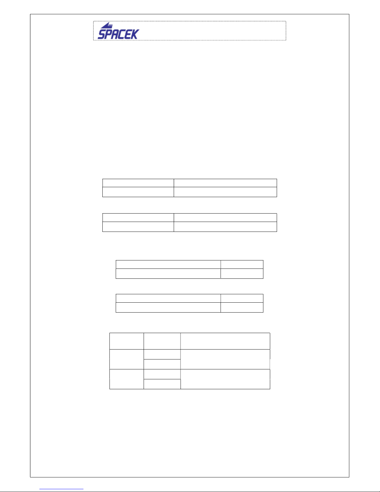
8.3. The list of work at periodical inspections
8.3.1. Inspection after first 25 hours and after 50 hours
Action
Nr. Description Performed
by Checked by
1
Generaly
Wash whole airframe using wet sponge and suitable
detergent. Remove cowling and covers and check fixing
of all parts (fuel, oil and electrical installation).
Check tightening and securing of all hardware.
2
Controls
Check control cables on damage. Check metal parts for
corrosion. Repair if necessary. Grease moving parts.
Check movement smootheness and its assembly.
3
Undercarriage
Remove covers and check free motion in the pins of
lower main leg consoles. Check free motion in the
tailwheel pin. Lubricate all pins usiing grease.
4
Tyres
Check pressure in tyre, its wear, discs and brake system.
Exchange tyre in case of excessive wear.
5
Engine
Check engine installation, oil, cooling baffles and all
hoses and controls on damage and wear. Check air filter
and wash it in gasoline if necessary.
6
Exhaust system
Check guskets, tubes and exhaust muffler for cracks,
leaks and missing parts.
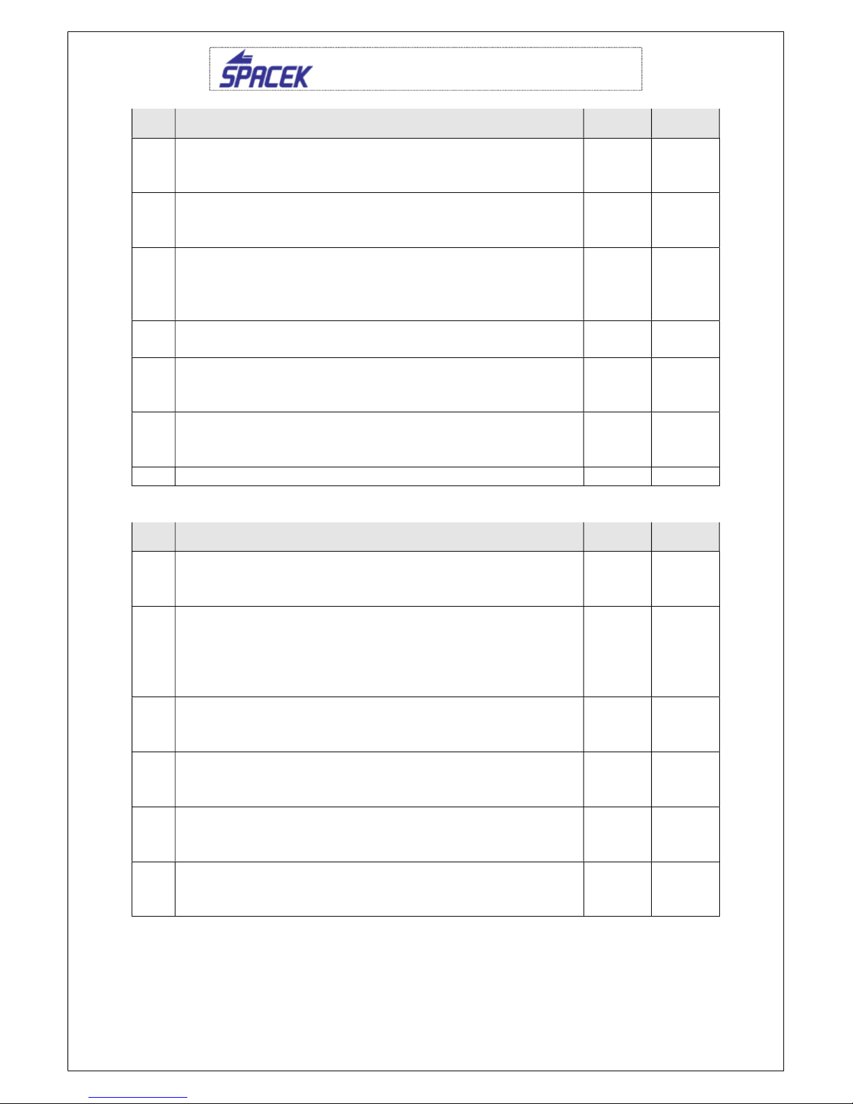
SD-1 Minisport TG, SE-33, P.O.H
18
Issue 1
Action
Nr. Description Performed
by Checked by
7
Cowling
Check cowling for loosenes, cracks or any damage.
Check completeness of hardware.
8
Propeller
Check tips and leading edge on damage. Repair using
epoxy or varnish..
9
Fuel system
Check tighteness of whole system and condition of all
hoses. Check smoothness of fuel valve run. Check fuel
filter and exchange if necessary.
10
Battery
Check voltage. Charge if necessary.
11
Cockpit
Clean using wet towel. Remove dirty on floor using
vacuum cleaner.
12
Cabine hood
Use agent suitable for cleaning of polycarbonates. Do
not use gasoline, alcohol etc.
7.3.2. Inspection after 100 hours or year examination
Action
Nr. Description Performed
by Checked by
1
Generaly
Clean all outside and inside skin of airplane. Check on
damage, wear and corrosion.
2
Front of the airplane
Check engine (see engine manual), hoses, engine
mount, propeller, battery, exhaust, firewall and rescue
system.
Check tightening and securing of hardware.
3
Fuel system
Check tube on cracks and valve function. Check fuel filter
and exchange it if necessary.
4
Fuselage
Check outside skin on cracks and inside structure on
possible rust.
5
Controls
Check free movement, wear of cable, tubing, bushes in
stick, brackets, mixer and rod ends. Check end stops.
6
Instruments
Check screws, fuses, placards, switches and pitot
system. Assure that all instruments work fine.

SD-1 Minisport TG, SE-33, P.O.H
19
Issue 1
Action
Nr. Description Performed
by Checked by
7
Wing
Check skin for cracks and possible bonding failure.
Check possible free movement in main and auxiliary
assembly pins.
Check flaperon hinges and possible free movement in
control connection pin.
8
Tails
Check skin for cracks and possible bonding failure.
Check possible free movement in all pins and their
securing.
9
Undercarriage
Check in accordance to 25 hours inspection.
10 Lubricate all moving parts-see e plan
11
Check all hinges of control surfaces and moving parts.
Perform repair action if free movement in hinge exceed
0,4 mm. The free play in hinge of horizontal tail should
not exceed 0,1 mm.
Assembly all dismantled parts after performed inspection and/or maintenance
and perform engine test run.
8.3.3. Lubricating plan
a) Lubricant used
Use suitable lubricating grease. (Castrol grease LM, Mobil grease MP etc.)
b) Lubricated places
All bearings
Whole controls of flaperons and horizontal tail
Main pin of HT at every disassembly
Antiservo tab hinges
Rudder hinges
Stick bearings
Pedals
Throttle bowden
Choke bowden
Hinge and pins of cabine hood
Table of contents


