Spacelabs Ultraview 91341 User manual

Exhibit H: User Manual 2
FCC ID: CM676A91341-600

Ultraview Digital Telemetry
91341 / 91343 / 91347
Operations Manual
071-0774-00 Rev. A
®

Copyright 2002 Spacelabs Medical, Inc.
All rights reserved. Contents of this publication may not be reproduced in any form without the written permission of Spacelabs
Medical, Inc. Products of Spacelabs Medical are covered by U.S. and foreign patents and/or pending patents. Printed in U.S.A.
Specifications and price change privileges are reserved.
Spacelabs Medical considers itself responsible for the effects on safety, reliability and performance of the equipment only if:
• assembly operations, re-adjustments, modifications or repairs are carried out by persons authorized by Spacelabs
Medical, and
• the electrical installation of the relevant room complies with the requirements of the standard in force, and
• the equipment is used in accordance with the operations manual.
Spacelabs Medical will make available, on request, such circuit diagrams, component part lists, descriptions, calibration instructions
or other information which will assist appropriately qualified technical personnel to repair those parts of the equipment which are
classified by Spacelabs Medical as field repairable.
Spacelabs Medical, Inc.
15220 N.E. 40th Street
P.O. Box 97013
Redmond, WA 98073-9713
U.S.A.
Telephone: 425-882-3700
Fax: 425-885-4877
Telex: 4740085 SPL UI
Spacelabs Medical Products Pty. Ltd.
Macquarie View Estates
Unit 1, 112-118 Talavera Road
North Ryde, N.S.W. 2113
AUSTRALIA
Telephone: 61-2-9878-6644
Fax: 61-2-9878-4820
Spacelabs Medical Products GmbH
Jochen Rindt Straße 25
1230 Vienna
AUSTRIA
Telephone: 43-1-616 52 37
Fax: 43-1-616 52 37 11
Spacelabs Medical B.V.
Airport Boulevard Office Park
Bessenveldstraat 25A
1831 Diegem
BELGIUM
Telephone: 32 2 7164026
Fax: 32 2 7164114
Spacelabs Medical Products, Ltd.
151 Superior Boulevard, Unit 1
Mississauga, Ontario L5T 2L1
CANADA
Telephone: 905-670-5880
Fax: 905-670-5883
CORPORATE OFFICES
Spacelabs Medical Instruments
(Tianjin) Co. Ltd.
6th Floor, Wang Jing Building
9 Wang Jing Zhong Huan South Road
Cho Yang District, Beijing 100015
CHINA
Telephone: 86-10-64731705
Fax: 86-10-64721707
Authorized EC Representative:
Spacelabs Medical Sarl
6, Allée des Saules
Europarc
94042 Créteil Cedex
FRANCE
Telephone: 33 (0) 1 45.13.22.44
Fax: 33 (0) 1 45.13.22.00
Spacelabs Medical GmbH
Airport Park
Willicher Damm 121+123
41066 Mönchengladbach
GERMANY
Telephone: 49-2161-8209-0
Fax: 49-2161-8209-222
Spacelabs Medical Limited
Suite 901 Tower 1
China Hong Kong City
33 Canton Road, Tsimshatsui
Kowloon
HONG KONG
Telephone: 852-2376-1370
Fax: 852-2376-2502
Spacelabs Medical, Inc.
c/o Impulse Business Club
F-22 South Extension Part 1
New Delhi 110049
INDIA
Telephone: 911 1464 5002
Fax: 911 4603338
Spacelabs Medical S.r.l.
Via Montecatini, 13
20144 Milano
ITALY
Telephone: 39-0-2/48958203
Fax: 39-0-2/48958204
Spacelabs Medical Ltd.
2F-3, No. 161. Sung Te Road
Taipei, Taiwan R.O.C.
TAIWAN
Telephone: 8862-2759-7238
Fax: 8862-2759-9060
Spacelabs Medical B.V.
Ringveste 9 A
3992 DD Houten
THE NETHERLANDS
Telephone: 31-(0)-30-638 5050
Fax: 31-(0)-30-638 5059
Spacelabs Medical Ltd.
Indigo Building
Unit 9, Mulberry Business Park
Fishponds Road
Wokingham, Berkshire RG 41 2GY
UNITED KINGDOM
Telephone: 44 118 9773 100
Fax: 44 118 9798 200
CAUTION:
• US Federal law restricts the devices documented herein to sale by, or on the order of, a
physician.

Spacelabs Medical is committed to providing comprehensive customer support beginning with your initial inquiry through
purchase, training, and service for the life of your Spacelabs Medical equipment. If you need our help along the way, we
offer these guidelines for fast, efficient response.
Acquiring Equipment
Sales Representative
800-522-7025 (U.S.A.)
or call your local office
To discuss your monitoring or clinical information
needs, to schedule product demonstrations, to order
equipment, or to schedule in-service education
Delivery Information
800-251-9910 (U.S.A.)
or call your local office
To find out when you can expect delivery of your
Spacelabs Medical equipment
Supplies Products
800-223-6467 (U.S.A.)
or call your local office
To order compatible supplies and accessories for your
equipment
Getting Started
Sales Representative
800-522-7025 (U.S.A.)
or call your local office
To arrange in-service education sessions
Answering Other Needs
Clinical Applications
800-522-7025 (U.S.A.) or 425-882-3700
or call your local office
To answer specific questions on arrhythmia products
and clinically related issues
First CallSM National Dispatch Center
800-522-7025 (U.S.A.)
800-942-7968 (Canada)
To call for service or to contact your assigned customer
service representative
Technical Support - Monitoring/Anesthesia
800-522-7025 (U.S.A.) or 425-882-3700
or call your local office
For technical support of all Ultraview®Care Network™
monitoring products and anesthesia products
Technical Support - Intesys Clinical Information Systems
800-210-0247 (U.S.A.) or 425-882-3700
or call your local office
For technical support of BirthNet®, Caremaster®,
Chartmaster®, QuIC, and WinDNA®products
Service Parts Department
800-547-8805 (U.S.A.) or 425-867-2039
or call your local office
For parts ordering and pricing information
Service Training Department
800-251-9910 (U.S.A.)
or call your local office
To arrange training of hospital biomedical and
anesthesia personnel
Regional Service Manager
800-522-7025 (U.S.A.)
800-942-7968 (Canada)
or call your local office
To obtain answers to general questions concerning
service issues and service contracts
Contacting Your Local Offices Outside the U.S.
Mississauga, Ontario
Canada
905-670-5880
Mönchengladbach
Germany
49-2161-8209-0
Kowloon
Hong Kong
852-2376-1370
Taipei
Taiwan
8862-2759-7238
Créteil
France
33 (0)1 45.13.22.44
Vienna
Austria
43-1-616 52 37
Milano
Italy
39-0-2/48958203
Beijing
China
86-10-64731705
Wokingham, Berkshire
U.K.
44 118 9773 100
New Delhi
India
911 1464 5002
Diegem
Belgium
32 2 7164026
Houten,
The Netherlands
31-(0)-30 638 5050

071-0774-00 Rev. A i
Chapter Page
1Contents
Introduction
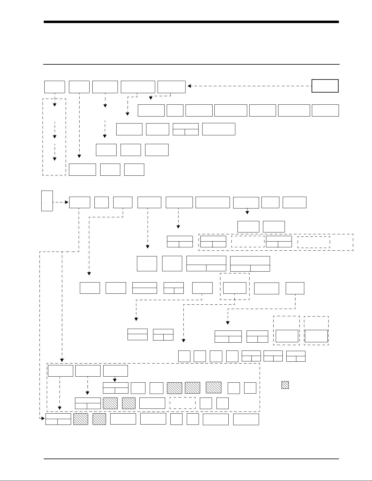
Directory of Keys - UCW and Ultraview 1700 . . . . . . . . . . . . . . . . . . . . . . . . . . . . . . . . . . . . . 1-1
Overview . . . . . . . . . . . . . . . . . . . . . . . . . . . . . . . . . . . . . . . . . . . . . . . . . . . . . . . . . . . . . . . . . 1-2
Cleaning . . . . . . . . . . . . . . . . . . . . . . . . . . . . . . . . . . . . . . . . . . . . . . . . . . . . . . . . . . . . . . . . . 1-9
Assigning a Telemetry Channel . . . . . . . . . . . . . . . . . . . . . . . . . . . . . . . . . . . . . . . . . . . . . . . 1-9
Tuning a Receiver for a Bedside . . . . . . . . . . . . . . . . . . . . . . . . . . . . . . . . . . . . . . . . . . . . . . . 1-9
Entering Patient Information . . . . . . . . . . . . . . . . . . . . . . . . . . . . . . . . . . . . . . . . . . . . . . . . . 1-10
Discharging a Patient . . . . . . . . . . . . . . . . . . . . . . . . . . . . . . . . . . . . . . . . . . . . . . . . . . . . . . 1-10
Acknowledging Signal Loss. . . . . . . . . . . . . . . . . . . . . . . . . . . . . . . . . . . . . . . . . . . . . . . . . . 1-11
Setting Battery Status Alarms . . . . . . . . . . . . . . . . . . . . . . . . . . . . . . . . . . . . . . . . . . . . . . . . 1-11
Controlling Patient-Initiated Recordings . . . . . . . . . . . . . . . . . . . . . . . . . . . . . . . . . . . . . . . . 1-11
Telemetry Alarm Message Summary . . . . . . . . . . . . . . . . . . . . . . . . . . . . . . . . . . . . . . . . . . 1-11
Accessories . . . . . . . . . . . . . . . . . . . . . . . . . . . . . . . . . . . . . . . . . . . . . . . . . . . . . . . . . . . . . . 1-12
ECG
Overview . . . . . . . . . . . . . . . . . . . . . . . . . . . . . . . . . . . . . . . . . . . . . . . . . . . . . . . . . . . . . . . . . 2-1
Setting Up ECG Monitoring . . . . . . . . . . . . . . . . . . . . . . . . . . . . . . . . . . . . . . . . . . . . . . . . . . . 2-1
Display Detail . . . . . . . . . . . . . . . . . . . . . . . . . . . . . . . . . . . . . . . . . . . . . . . . . . . . . . . . . . . . . 2-4
Monitoring Paced ECG Patients . . . . . . . . . . . . . . . . . . . . . . . . . . . . . . . . . . . . . . . . . . . . . . . 2-5
Restoring Default Settings. . . . . . . . . . . . . . . . . . . . . . . . . . . . . . . . . . . . . . . . . . . . . . . . . . . . 2-6
Changing the Display Resolution . . . . . . . . . . . . . . . . . . . . . . . . . . . . . . . . . . . . . . . . . . . . . . 2-6
Selecting Options for Lead Display . . . . . . . . . . . . . . . . . . . . . . . . . . . . . . . . . . . . . . . . . . . . . 2-7
ECG Alarm Message Summary . . . . . . . . . . . . . . . . . . . . . . . . . . . . . . . . . . . . . . . . . . . . . . . 2-9
SpO2 (91343 only)
Overview . . . . . . . . . . . . . . . . . . . . . . . . . . . . . . . . . . . . . . . . . . . . . . . . . . . . . . . . . . . . . . . . . 3-1
Setting Up SpO2 Monitoring . . . . . . . . . . . . . . . . . . . . . . . . . . . . . . . . . . . . . . . . . . . . . . . . . . 3-2
Ensuring Accurate Monitoring . . . . . . . . . . . . . . . . . . . . . . . . . . . . . . . . . . . . . . . . . . . . . . . . . 3-3
Setting or Adjusting Alarm Limits . . . . . . . . . . . . . . . . . . . . . . . . . . . . . . . . . . . . . . . . . . . . . . 3-4
Setting SpO2 Data Averaging Period and Sampling Interval . . . . . . . . . . . . . . . . . . . . . . . . . 3-6
Viewing Pulse Rate . . . . . . . . . . . . . . . . . . . . . . . . . . . . . . . . . . . . . . . . . . . . . . . . . . . . . . . . . 3-7
SpO2 with Intra-Aortic Balloon Pumps . . . . . . . . . . . . . . . . . . . . . . . . . . . . . . . . . . . . . . . . . . 3-7
Using SpO2 with Neonates . . . . . . . . . . . . . . . . . . . . . . . . . . . . . . . . . . . . . . . . . . . . . . . . . . . 3-8
SpO2 Alarm Message Summary. . . . . . . . . . . . . . . . . . . . . . . . . . . . . . . . . . . . . . . . . . . . . . . 3-8
NIBP (91343 only)
Overview . . . . . . . . . . . . . . . . . . . . . . . . . . . . . . . . . . . . . . . . . . . . . . . . . . . . . . . . . . . . . . . . . 4-1
Setting Up NIBP Monitoring . . . . . . . . . . . . . . . . . . . . . . . . . . . . . . . . . . . . . . . . . . . . . . . . . . 4-2
Setting Up the ABP Monitor . . . . . . . . . . . . . . . . . . . . . . . . . . . . . . . . . . . . . . . . . . . . . . . . . . 4-3
Setting or Adjusting Alarm Limits . . . . . . . . . . . . . . . . . . . . . . . . . . . . . . . . . . . . . . . . . . . . . . 4-7
Displaying New or Previous Readings . . . . . . . . . . . . . . . . . . . . . . . . . . . . . . . . . . . . . . . . . . 4-8
NIBP Alarm Message Summary . . . . . . . . . . . . . . . . . . . . . . . . . . . . . . . . . . . . . . . . . . . . . . . 4-9

Ultraview Care Network
ii 071-0774-00 Rev. A
Alarms
Alarm Message Summary . . . . . . . . . . . . . . . . . . . . . . . . . . . . . . . . . . . . . . . . . . . . . . . . . . . 5-1
ECG Alarm Messages . . . . . . . . . . . . . . . . . . . . . . . . . . . . . . . . . . . . . . . . . . . . . . . . . . . . . . 5-2
SpO2 Alarm Messages. . . . . . . . . . . . . . . . . . . . . . . . . . . . . . . . . . . . . . . . . . . . . . . . . . . . . . 5-3
NIBP Alarm Messages . . . . . . . . . . . . . . . . . . . . . . . . . . . . . . . . . . . . . . . . . . . . . . . . . . . . . . 5-4
Telemetry Alarm Messages . . . . . . . . . . . . . . . . . . . . . . . . . . . . . . . . . . . . . . . . . . . . . . . . . . 5-5
Symbols
1
071-0774-00 Rev. A 1-1
!• Based on features purchased, more or fewer keys may appear here than on your menu screens.
!• Based on features purchased, more or fewer keys may appear here than on your menu screens.
SCREEN
FORMAT TONES MONITOR
CONFIGURATION
PRIVILEGED
ACCESS.
MONITOR
SETUP
CONTRASTBRIGHTNESS
ADMIT CHANGE
DATA DISCHARGE
SCALED
DISPLAY
TIME/
DATE
REMOTE
ALARMS
ALARM
WATCH
KEY
TONE
CLINICAL LEVEL: Select Parameter
MONITOR CONFIGURATION
ADMIT/DISCHARGE - Select Function (see Admit/Discharge)
MONITOR SETUP - Select type of tone to change (see Alarms)
MONITOR SETUP
E
C
G
CLEAR
MEMORY
SAVE
MEMORY
ECG - RELEARN
2nd LEAD
ON OFF
RATE
SOURCE
SWEEP
SPEED
QRS MONITOR PA CED
YES NO CONFIG
TONE EXTENDED
ADULT
INFANT
Select primary heart rate source
ECG - CHANNEL FORMAT
ECG - SETUP
ECG - CONFIG
ALARM
LIMITS SIZE SETUP LEAD
SELECT
CHANNEL
FORMAT
SUSPEND
PROCESSING PRINT
ECG MENU - (Multi-Lead) (MultiviewTM II option with Arrhythmia and Review ON - used with 91343/91347 transmitter)
REVIEW
2nd LEAD
xx
1st LEAD
xx ON OFF
ECG ART UA SPO2
Enable alternate rate source(s)
ARR
ON OFF
UA
ON OFF
ART
ON OFF
SPO2
ON OFF
TM
SETUP
RESTORE
SETTINGS
AUTO LEAD SWITCH
ASSIGN
TM BED
PT RECORD
YES NO
LO BAT
ON OFF
SET TM
CHAN
ECG - TM SETUP
Central
only
Bedside
only
Bedside
monitors only
select bed
(or subnet,
then bed)
RELEARN
SpO2
ON OFF
NIBP
ON OFF
SpO2(IABP)(NEO)
(RATE)(AVG)
91343 only
ECG ALM
ON OFF
ST LIMITS
CH 1
ABN IN
ROW=XX
ABN PER
MIN=XX
↑
ST LIMITS
CH 2
ABN IN
ROW=XX
HI=
XXX
LO=
XXX
SPO2 ALM
ON OFF
ALM DELAY
=XXs
MSG ALM
DELAY =XXs
↑
↓
HI=
XXX
LO=
XXX
NIBP ALM
ON OFF
↑
↓
HI=
XXX
LO=
XXX
NIBP ACTIVE
(NO CABLE)
SPO2 ALARM
LIMITS
NIBP ALARM
LIMITS
LIMITS
91347
(and
91343
with
SpO2
and
NIBP
turned
OFF)
91343
select ECG 1
Select
zone
waveform
select bed
(or subnet,
then bed)
RECORDER
DESTINATION
ECG - LEAD SELECT
ON OFF
SINGLE LEAD ALARM
ECG ALARM
CLOCK
ON OFF
ACTIVATE
SCREEN SAVER
PRESELECTED
RECORDINGS
UNITS OF
MEASURE
USER ACCESS
ENABLE
ALARM
SETUP
ADMIT/
DISCHARGE
MPT=ON*
91343 only MPT=ON*
*Multi-parameter Telemetry (MPT):
required settings in
Module Configuration Manager
↑
DIA MEAN
SYS Limit keys will flash on alarm
Directory of Keys - UCW and Ultraview 1700
1Introduction

1-2 071-0774-00 Rev. A
Contents
1
1Introduction
Overview
The 90478-A digital telemetry receiver module, when used in conjunction with
Spacelabs Medical telemetry transmitters, an Ultraview or PCMS™monitor, and
90479-A modular receiver housing, provides continuous monitoring of
electrocardiographic signals in order to detect abnormal cardiac rhythms,
including asystole, ventricular fibrillation, and ventricular tachycardia. In addition,
when used with the 91343 digital telemetry multi-parameter transmitter and the
90217 Ambulatory Blood Pressure (ABP) monitor, monitoring of
electrocardiographic signals is augmented by the availability of continuous or
episodic SpO2measurements and episodic noninvasive blood pressure (NIBP)
measurements.
Directory of Keys - UCW and Ultraview 1700 . . . . . . . . . . . . . . . . . . . . . . . . . . .1
Overview . . . . . . . . . . . . . . . . . . . . . . . . . . . . . . . . . . . . . . . . . . . . . . . . . . . . . . .2
Cleaning . . . . . . . . . . . . . . . . . . . . . . . . . . . . . . . . . . . . . . . . . . . . . . . . . . . . . . .9
Assigning a Telemetry Channel . . . . . . . . . . . . . . . . . . . . . . . . . . . . . . . . . . . . .9
Tuning a Receiver for a Bedside. . . . . . . . . . . . . . . . . . . . . . . . . . . . . . . . . . . . .9
Entering Patient Information . . . . . . . . . . . . . . . . . . . . . . . . . . . . . . . . . . . . . . .10
Discharging a Patient . . . . . . . . . . . . . . . . . . . . . . . . . . . . . . . . . . . . . . . . . . . .10
Acknowledging Signal Loss . . . . . . . . . . . . . . . . . . . . . . . . . . . . . . . . . . . . . . .11
Setting Battery Status Alarms . . . . . . . . . . . . . . . . . . . . . . . . . . . . . . . . . . . . . .11
Controlling Patient-Initiated Recordings . . . . . . . . . . . . . . . . . . . . . . . . . . . . . .11
Telemetry Alarm Message Summary . . . . . . . . . . . . . . . . . . . . . . . . . . . . . . . .11
Accessories. . . . . . . . . . . . . . . . . . . . . . . . . . . . . . . . . . . . . . . . . . . . . . . . . . . .12

Introduction
071-0774-00 Rev. A 1-3
Intended Use
As an option, on adult patients, additional abnormal cardiac rhythms, such as
ventricular runs, tachycardia, and ST segment deviations can be detected. The
Ultraview Digital Telemetry System also provides a means for the episodic
monitoring of NIBP signals to detect abnormal events such as high and low blood
!• Spacelabs Medical’s telemetry equipment complies with Part 15
and Part 95 of the FCC Rules and with RSS-210 of Industry
Canada and with requirements of other national spectrum
management authorities. Repeated here are operational
cautions for biomedical telemetry from the FCC Rules
(47CFR15.242(f)):
“Biomedical telemetry devices must not cause harmful
interference to licensed TV broadcast stations or to other
authorized radio services, such as operations on the
broadcast frequencies under subpart G and H of part 74 of
this chapter, land mobile stations operating under part 90 of
this chapter in the 470-512 MHz band, and radio astronomy
operation in the 608-614 MHz band. (See section 15.5). If
harmful interference occurs, the interference must either be
corrected or the device must immediately cease operation
on the occupied frequency. Further, the operator of the
biomedical telemetry device must accept whatever level of
intereference is received from other radio operations. The
operator (health care facility) is responsible for resolving
any interference that occurs subsequent to the installation
of these devices.”
• Medical telemetry equipment is only for installation and use in
hospitals and health care facilities. It is not permitted for use in
vehicles that operate outside of the medical facility premises.
The user of this equipment is not authorized to make any
changes or alterations that could compromise the national
certifications.
• Operation of telemetry equipment in the 608 - 614 MHz, 1395 -
1400 MHz, 1427 - 1429.5 MHz, and 1429.5 - 1432 MHz parts of
the Wireless Medical Telemetry Service (WMTS) and in
authorized spectrum of each country, may be geographically
restricted by government regulation. Spacelabs Medical
Customer Service can assist in evaluating if a hospital’s location
requires coordination with a protected radio astronomy
observatory or other protected government site that may be
within an 80-km (54-mile) radius.
WARNING:
• Changes or modifications not expressly approved by
Spacelabs Medical will void the user’s authority to operate
the equipment.

Ultraview Digital Telemetry
1-4 071-0774-00 Rev. A
pressure. Finally, it provides a means for both continuous and episodic monitoring
of pulse blood oxygen saturation signals in order to detect oxygen desaturation
caused by abnormal pulmonary/circulatory functions.
The Spacelabs Medical 91341, 91343, and 91347 Ultraview Digital Telemetry
Systems are intended for use with either adult or neonatal patients in a hospital
environment. When the NIBP option is selected in the 91343 configuration, the
NIBP feature is to be used with adult patients only.
Transmitters
The transmitter is a small, battery-powered device carried by the patient that
monitors ECG activity and SpO2/NIBP (91343 only) data, and transmits this
information to the telemetry receiver module.
• The 91341 transmits two leads of ECG and use up to five lead wires. One or
two leads may be displayed.
• The 91343 and 91347 transmit four leads of ECG and use up to five lead
wires. However, only two leads may be displayed simultaneously.
• The 91343 is also capable of transmitting numerical NIBP and SpO2data.
This data is displayed simultaneously with that of the ECG waveform data.
Each telemetry channel requires its own transmitter operating on a unique radio
frequency. Channel receivers are tuned from the Ultraview monitor touchscreen to
receive the available transmitter frequencies.
!• Episodic monitoring of NIBP values and continuous and
episodic monitoring of blood oxygen saturation values are only
supported in conjunction with ECG monitoring. SpO2 and NIBP
alarms are inhibited by ECG leads-off condition.
WARNING:
• The Ultraview Digital Telemetry transmitters are
contraindicated for use with other medical instrumentation
(e.g., respiration monitors using impedance
pneumography, electrocautery, etc.) that source electrical
current through the patient. Further, telemetry monitoring
is contraindicated for the Operating Room environment.
!• Operation of this equipment may be subject to licensing
requirements by your local telecommunications authority.
Please check with your Spacelabs Medical customer service
representative.

Introduction
071-0774-00 Rev. A 1-5
Up to five standard disposable silver/silver chloride chest electrodes are
connected to the patient. The ECG lead wires are attached to these electrodes
and connected to the transmitter. Lead wires that are poorly connected to the
patient (including compromised electrode connections) are locally detected and
identified with flashing indicators at the ECG patient input connector. A patient-
operated RECORD button initiates an ECG strip at the system printer, if this
feature is enabled at the central or bedside monitor.
WARNING:
• Medical telemetry spectrum allocations may be assigned to
frequencies already allotted to other priority users. This
means that telemetry operations may be exposed to radio
frequency interference that may disrupt or impede
telemetry patient monitoring during the life of this
equipment. You are urged to regularly consult with
applicable local and federal regulatory agencies (e.g., FCC,
FDA, etc.) regarding the locations and frequencies of other
spectrum users in your geographic area. Spacelabs
Medical service representatives may be able to assist you
in reconfiguring your equipment frequencies to reduce the
risk of interference. Spacelabs Medical cannot, and does
not, guarantee interference-free telemetry operation.
CAUTION:
• This device has a limited bandwidth range of .05 to 30 Hz,
which may adversely affect the recording of high
frequency components in the ECG signal, especially when
the morphology of the ECG changes rapidly.
• This device has a limited dynamic range of ±4 mV, which
may render the device vulnerable to saturation by ECG
signals with amplitudes higher than 4 mV.
• To clean the transmitter, use only the following solutions
per the manufacturer’s labeling: isopropyl alcohol (70%),
hydrogen peroxide, Cidex, Betadine, and Clorox. Use of
cleaning solutions other than those listed will VOID the
warranty of the digital telemetry transmitter cases.
• Patients should not use any type of electronic equipment
(e.g., portable radios, cellular telephones, pagers, personal
computers, etc.) while connected to any medical electronic
device without in-situ evaluation by the biomedical
engineering staff.
• Use of 2-way radio equipment and other personal
communication devices must be evaluated in-situ to
assess the potential for disruption of monitoring.
!• Clean the transmitter after each use. The transmitter does not
require any preventive maintenance other than cleaning.

Ultraview Digital Telemetry
1-6 071-0774-00 Rev. A
Transmitter Batteries
A 9-volt alkaline battery is recommended for standard use in the digital telemetry
transmitter. A 9-volt lithium battery may also be used for applications requiring
more extended battery service life.
Always observe the battery position and polarity as illustrated at the bottom of the
battery compartment. After battery installation, close and latch the compartment
cover. The transmitter begins transmitting as soon as the battery is in place.
Battery Disposal
Both the 91341, 91343, and 91347 Ultraview Digital Telemetry transmitters are
operated by 9-volt primary (non-rechargeable) batteries that must be properly
disposed when discharged. The batteries specified may be of either alkaline or
lithium chemistry. Attempting to recharge these batteries is not recommended and
can result in leaking, venting, or explosion.
Follow the battery manufacturer’s recommended handling procedure for both
types of batteries: Collect and transport the batteries in a manner that prevents
short circuit, compacting, mutilation, or any other physical abuse or electric
handling that would destroy their physical integrity. Exposure to high temperatures
or fire can cause the batteries to leak, vent, or explode.
Disposing of used batteries may be subject to national, state/provincial, and/or
local regulation, which varies depending on jurisdiction.
The recommended disposal procedure for alkaline batteries is to transport them to
a hazardous waste landfill. Since these batteries may not be classified as
hazardous waste, they may be transported to the disposal facility as non-
hazardous waste.
The recommended disposal procedure for lithium batteries is to transport them as
hazardous waste to a hazardous waste facility. If the batteries are physically
sound, disposal of these discharged batteries in a hazardous waste landfill may
be permissible. If the batteries are leaking, cracked, opened, vented, or otherwise
not physically sound, they must be transported to a qualified hazardous waste
facility.
!• Whenever the transmitter is not in use, the battery should be
removed. Insert a battery only when the transmitter is being
used with a patient.
• The LOW BATTERY message appears and an alarm tone
sounds (if LO BAT is set to ON) when the transmitter battery
voltage falls below approximately 7.0 volts. When this message
appears, the transmitter has approximately three hours of
operating time left, depending on transmitter type, selected
options, and the type of battery.
• When the battery level falls below approximately 7.0 volts, the
low battery LED on the transmitter will flash once every 15
seconds. When the battery level falls below 6.0 volts, the low
battery LED will flash once every two seconds. When the
battery level falls below 5.5 volts, the SpO2and NIBP functions
will shut down. The LOW BATTERY message may appear after
the low battery LED on the transmitter begins to flash.

Introduction
071-0774-00 Rev. A 1-7
Digital Telemetry Receiver Module
The 90478 telemetry receiver module plugs into a bedside, central, or transport
monitor, or into a digital telemetry module housing. The receiver module receives
patient vital signs data from the transmitter. This data is reconstructed by the
receiver module, displayed on the monitor and analyzed as described in the ECG,
Arrhythmia, and ST Analysis chapters of the UCN Operations Manual, and in the
SpO2and NIBP sections in this chapter.
Digital Telemetry Receiver Housing
The telemetry receiver housing can hold up to eight separate telemetry receiver
modules. Except for the ON/OFF switches, there are no operator controls on the
module housing. For normal operation with AC mains power applied, the AC
mains indicator light on the front panel of the housing must be illuminated.
Operating the system without AC mains power is limited to ten minutes of battery
backup time.
WARNING:
• Telemetry systems may be more susceptible to
interference than hardwired systems, which may impact
signal quality.
• Operation of hand-held, wireless telephone equipment
(e.g., cordless telephones, cellular telephones) near
telemetry systems may cause interference and should be
discouraged. While personal communication devices are
turned on, a separation of > 6.5 feet (> 2 meters) should be
maintained between personal communication devices and
interior walls, the patient cables, and any electronic
medical device to which the patient may be connected.
Patients should not use any type of electronic
communication equipment while connected to any
electronic medical device without an on-site evaluation by
the biomedical staff. Two-way radio equipment and other
personal communication devices must be evaluated on
site to determine if additional space limitations are needed.
• Do not install a telemetry receiver module into a bedside
that is currently equipped with any other ECG module,
hardwired or telemetry (or SpO2 module or NIBP module, if
the 91343 is operating with that specific receiver module).
Doing so may cause inaccurate patient data displays at
remote monitors.
Ultraview Digital Telemetry
1-8 071-0774-00 Rev. A
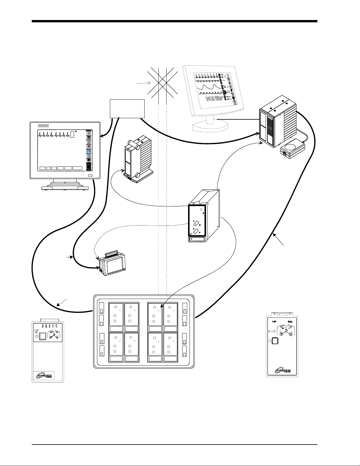
Figure 1-1: Ultraview Digital Telemetry System
Diversity
Antenna
System
Ultraview 1700
receiver module
Digital Telemetry Module Housing
SDLC
90479-A
90478-Q/T/V
E
C
G
VI
ST=0.00
A=3
70
HELP: Acce ss controls that pertai n to ECG
ECG MENU
ALARM
LIMITS SIZE SETUP LEAD
SELECT
CHANNEL
FORMAT
SUSPEND
PROCESSING
UCW bedside or central
remote module
91341/91347
SDLC
NOTE: The UCW bedside connects to
the remote module housing, and the
UCW central connects to the digital te-
lemetry module housing.
Digital Telemetry
Ultraview 1050/1030
Ultraview 1500 or
91343
Digital Telemetry
Multi-parameter Transmitter
ECG Transmitters
housing
shown with flat
panel display
ETHERNET
HUB
10BaseT
Ethernet
Option

Introduction
071-0774-00 Rev. A 1-9
Cleaning
Clean the transmitter after each use. The transmitter does not require any
preventive maintenance other than cleaning.
To clean the transmitter, use only the following agents.
• Mild soap and water solution
• U.S. Pharmacopoeia (USP) green soap
• Sodium hypochlorite solution (1:10 dilution of household bleach in water)
• Phenolic germicidal detergent solutions (1% aqueous solutions)
• Isopropyl alcohol solution (70%)
Assigning a Telemetry Channel
Telemetry transmitters have preassigned channel frequencies. This channel
number is identified on the back of the case and cannot be changed. To receive
this telemetry channel, one of the receivers in the telemetry receiver housing must
be tuned to its assigned frequency.
Tuning a Receiver for a Bedside
The central monitor must be tuned by a qualified service person, but the bedside
monitor may be tuned using the ECG TM SETUP menu. You may use this menu
to tune the receiver module to the pre-assigned channel frequencies on the
telemetry transmitter.
!• Tuning telemetry receiver modules to transmitter channels at
the central monitor must be done by a qualified service person.
• Your central monitor can be configured to remember beds that
are assigned to individual telemetry channels using the Module
Configuration Manager feature. These beds are permanently
assigned until you unassign or reassign them. Refer to the
Module Configuration Manager chapter of the UCN Operations
Manual.
!• The module default is set for North America using UHF band
operation. For alternate band operation, or if operating in
another country, you must select the appropriate frequency
band using the Module Configuration Manager.
To set up the central for ECG (if
bed name not remembered):
1Touch key label that matches
transmitter's frequency
2Select bed/room number for
transmitter channel
To set up the central for ECG
(MPT=OFF) (UCW and 1700):
1Touch MONITOR SETUP
2Touch SCREEN FORMAT
3Select subnet and bed/room
number
4Select ECG and then desired
zone
To tune a receiver module at
bedside:
1Touch ECG
2Touch SETUP
3Touch TM SETUP
4Touch SET TM CHANNEL
5Select the digit to change. Use
the ↑ ↓ keys to select the value
for that digit
6Repeat for all digits as
necessary
7Touch STORE

Ultraview Digital Telemetry
1-10 071-0774-00 Rev. A
Entering Patient Information
The ADMIT/DISCHARGE menu enables you to enter a patient identification (ID)
number, name, height, weight, and body surface area (BSA).
Discharging a Patient
A patient is discharged by first removing the battery from the 91343/91347
Ultraview Digital Telemetry Transmitter. The monitor displays the squelch
waveform followed by the message INTERMITTANT SIGNAL LOSS after a short
delay. An alarm condition is displayed on the monitor because of the signal loss.
The message IS SIGNAL LOSS PERMANENT? appears with keys labeled YES
and NO in the waveform zone. Touch YES to indicate that the signal loss is
permanent. Touch NO to cancel the discharge operation.
The next message displayed is DISCHARGE THE PATIENT?. Touch YES to
continue the discharge process. Touch NO to cancel the discharge operation.
The monitor displays PURGES DATA-ARE YOU SURE? Touch YES to discharge
the patient and erase all patient data. The intermittent signal loss alarm is then
canceled. Touch NO to cancel the discharge operation and cause the message IS
SIGNAL LOSS PERMANENT? to appear in the waveform zone.
!• Admitting a new patient purges data from the previous patient
on that telemetry channel.
WARNING:
• During INTERMITTANT SIGNAL LOSS message activation,
the display of SpO2and NIBP data is disabled.
To admit a patient:
1Touch MONITOR SETUP
2Touch ADMIT/DISCH
3Select subnet (UCW and 1700
only)
4Select bed/room number for
channel
5Touch ADMIT
6Select YES
7Use keyboard to enter patient
info (UCW and 1700 only)
8Select ID, NAME, HEIGHT,
WEIGHT, or BSA,
UV1050/1500 only)
9Enter data using pop-up keypad
or keyboard ( UV1050/1500
only)
10 Touch ENTER
11 Repeat steps 7 - 10 until all data
has been entered
12 Touch ACCEPT (UCW and
1700 only)
To discharge a patient:
1Remove battery
2Disconnect the transmitter from
the patient
3Select YES to confirm signal
loss permanent
4Select YES to discharge
5Select YES to purge data

Introduction
071-0774-00 Rev. A 1-11
Acknowledging Signal Loss
When a telemetry signal is lost because the transmitter is out of range or the
battery is removed, the receiver initiates a squelch condition indicated by a
triangular waveform that replaces the normal ECG waveform and SQUELCH is
included in the edge print for any strip chart recording. The ECG trace
automatically begins again if the lost signal returns.
After eight seconds of signal loss, the IS SIGNAL LOSS PERMANENT? message
appears. Selecting NO suspends alarm tones. Selecting YES displays the
message DISCHARGE THE PATIENT? Selecting YES again, provides you with
the message PURGES DATA-ARE YOU SURE? Selecting YES a third time,
discharges the patient from the system and purges all data for that patient.
Selecting NO at any point in this sequence returns you to the previous option.
Setting Battery Status Alarms
The telemetry battery alarm tone, and a LOW BATTERY message in the ECG
zone involved, alerts you to a low battery condition in the transmitter. You may
disable the low battery alarm tone, if your bedside or central is configured to
do so.
The factory default setting for low battery alarm is ON.
Controlling Patient-Initiated Recordings
If the Patient Record function is activated (PT RECORD is YES) in the ECG TM
SETUP menu, the patient may initiate a recording by pressing the RECORD
button on the front of the transmitter.
Telemetry Alarm Message Summary
INTERMITTENT SIGNAL LOSS
The intermittent signal loss message indicates that the patient may be out of
antenna range, or the battery is depleted. Return the patient into antenna range.
Check that the battery is functioning properly.
LOW BATTERY
A Low Battery Message indicates that the battery is weak. After this message
appears, the battery has approximately three hours of useful life left (depending
on the type of battery used). Install new battery.
SIGNAL INTERFERENCE
The Signal Interference message indicates, via the displayed triangle squelch
waveform, that an interfering signal has been detected.
PERMANENT SIGNAL LOSS
The Permanent Signal loss message indicates that no RF signal is being
detected.
To control low battery alarms:
1Touch ECG
2Touch SETUP
3Touch TM SETUP
4Select LO BAT ON or OFF
To control transmitter's Patient
Record function:
1Touch ECG
2Touch SETUP
3Touch TM SETUP
4Select PT RECORD YES or NO

Ultraview Digital Telemetry
1-12 071-0774-00 Rev. A
Accessories
Refer to the Spacelabs Medical Supplies Products Catalog for availability of
accessories. Some of the more commonly used accessories are listed below.
Digital Telemetry Accessories
91341/91343/91347 telemetry transmitter pouch 015-0500-00
Belt clip 344-0020-00
Receiver whip antenna (UHF) 117-0040-00
Receiver housing protective cover 200-0180-00
ECG Accessories
DIN standard safety lead wire set, 5 wire 012-0605-00
Adult general purpose electrode 015-0097-01
Holter/stress disposable electrode 392015-001
SpO2Accessories
Nellcor SpO2adapter cable 700-0014-00
Nellcor SpO2sensors Adult/Neonatal (N-25) 690-0006-00
Pediatric (P-20) 690-0007-00
Adult disposable (D-25) 690-0001-00
Finger clip (DS-100A) 690-0003-00
Nasal (R-15) 690-0005-00
Oxiband A/N 690-0004-00
Oxiband pediatric/infant reusable sensor P/I 690-0039-00
NIBP Accessories
ABP adapter cable 700-0015-00
ABP Pouch 015-0501-00
ABP Shoulder Strap 016-0262-00
Cuff assembly, child (13-20 cm) w/ hose 015-0118-01
Cuff assembly, small adult (17-26 cm) w/ hose 015-0067-01
Cuff assembly, adult (24-32 cm) w/ hose 015-0068-02
Cuff assembly, large adult (32-42 cm) w/ hose 016-0077-01
Cuff assembly, extra-large adult (38-50 cm)
w/ hose and cuff support harness 016-0109-01
ABP Report Management System 90121

Introduction
071-0774-00 Rev. A 1-13
ABP Report Management System
Adaptor Cable 012-0097-02
90121 ABP Report Management System
Operations Manual 070-0529-xx
90217 ABP Monitor Operations Manual 070-0137-xx
Ultraview Care Network Operations Manual 070-1001-xx

This manual suits for next models
2
Table of contents
Other Spacelabs Medical Equipment manuals

Popular Medical Equipment manuals by other brands

Otto Bock
Otto Bock DynamicArm Instructions for use

Nipro
Nipro TRUEdraw quick start guide

OPTIKON
OPTIKON Keratron Piccolo Installation and operating manual

Boston Scientific
Boston Scientific RELIANCE 4-FRONT DF4-LLHH PHISICIAN'S LED MANUAL

Tomey
Tomey OA-2000 instruction manual

Beka Hospitec
Beka Hospitec NORA Alu operating manual


