Tomey OA-2000 User manual

683A9090-0Q
INSTRUCTION MANUAL
OPTICAL BIOMETER
OA-2000
Read this manual thoroughly before using the
instrument to ensure proper and safe operation.
Contact Tomey Corporation or our local distributor if
you have any questions or you encounter any
problems during operation.
■ Always follow the operation
procedures described in this manual.
■ Keep this manual in a readily
accessible location while operating the
instrument.
■ Contact our local distributor if you lose
this manual.


i-1
■
i Important Safety Information
■ Do not install this instrument in a location where explosives or inflammable
substances are used or stored. Otherwise, fire or explosion may occur.
■ Do not remove the cover of the instrument. You may be directly exposed to
high voltage sections.
■ Do not disassemble or modify the instrument. You may be directly exposed
to high voltage sections.
■ Disconnect the power cord from the instrument before servicing the
instrument. Otherwise, you may get an electric shock.
■ Do not place water or chemicals on the instrument. Any water or chemicals
entering the instrument may cause an electric shock or failure.
■ Only use the specified terminal for connection of the instrument. Using
another type of terminal may result in failure of the instrument.
■ This instrument is a diagnostic/measuring device specially designed for
ophthalmology. Never use the instrument for other purposes.
■ The external output terminal is not isolated from the internal circuit.
Inappropriate wiring may damage the internal circuit. Be sure to contact
Tomey Corporation beforehand when using the external output terminal.

■
i-2
■ This device complies with FCC RF radiation exposure limits set forth for an
uncontrolled environment. The antenna used for this transmitter must be
installed to provide a separation distance of at least 20 cm from all persons
and must not be co-located or operated in conjunction with any other
antenna or transmitter.

ii-1
■
ii How to read this manual
Outline
This manual is structured as follows.
1. PRIOR TO USE
Describes safety precautions and important information to be
understood before installing and using the instrument.
2. NAMES AND FUNCTIONS
Describes names and functions of each section of the instrument.
3. OPERATION PROCEDURES
Describes information required for installing and using the instrument.
4. TECHNICAL INFORMATION
Describes useful technical information about the instrument.
5. INSPECTION AND MAINTENANCE
Describes procedures for replacing consumable parts, etc. that the
user of the instrument should normally conduct.
6. TROUBLESHOOTING
Describes how to solve problems.
7. CONSUMABLES AND OPTIONAL EQUIPMENT
Describes consumable parts and optional equipment.
8. Specifications
Describes the specifications of the instrument.

■
ii-2
SYMBOLS USED IN THIS MANUAL
Descriptions accompanied by the symbols below indicate the
following:
■ This is a precaution that, if unheeded, will result in a
hazardous situation where there is an imminent danger of
serious injury or death.
■ This is a precaution that, if unheeded, could result in a
hazardous situation where there is a possibility of serious
injury or death.
■ This is a precaution that, if unheeded, may result in a
situation where there is a possibility of minor or moderate
injury or damage to property.
■ This is additional information which may contain special
precautions on company policies related, either directly
or indirectly, to the safety of personnel or to the
protection of property.

iii-1
■
iii Contents
iImportant Safety Information ................................................................................................................. i-1
ii How to read this manual ....................................................................................................................... ii-1
Outline...........................................................................................................................................................ii-1
SYMBOLS USED IN THIS MANUAL............................................................................................................ii-2
iii Contents................................................................................................................................................. iii-1
1. PRIOR TO USE ....................................................................................................................................... 1-1
1.1 Precautions for operation....................................................................................................................... 1-1
1.2 Checking package contents................................................................................................................... 1-5
1.3 Glossary................................................................................................................................................. 1-6
1.4 Overview ................................................................................................................................................ 1-9
2. NAMES AND FUNCTIONS ..................................................................................................................... 2-1
2.1 Physician's side ..................................................................................................................................... 2-1
2.2 Patient's side.......................................................................................................................................... 2-1
2.3 Sides of the main unit ............................................................................................................................ 2-2
2.4 Screen.................................................................................................................................................... 2-3
2.4.1 Basic structure and common items ............................................................................................. 2-3
2.4.2 Screens in optical mode .............................................................................................................. 2-4
2.4.3 Screens in each ultrasound mode............................................................................................... 2-9
2.4.4 IOL power calculation screen .................................................................................................... 2-12
2.5 Symbols used for marking ................................................................................................................... 2-14
3. OPERATION PROCEDURES.................................................................................................................. 3-1
3.1 Safety precautions ................................................................................................................................. 3-1
3.2 Preparation before use .......................................................................................................................... 3-1
3.2.1 Connections................................................................................................................................. 3-1
3.2.2 Connecting the axial length and corneal thickness measurement instrument AL-4000 ............. 3-6
3.2.3 Turning the power on and adjustment after turning the power on............................................... 3-7
3.2.4 Switching between optical (OPT) mode and ultrasound (US) mode........................................... 3-8
3.2.5 Entering the patient data ............................................................................................................. 3-8
3.2.6 Clear all measurement data (preparation for measuring a new patient)................................... 3-10
3.2.7 Selecting an eye.........................................................................................................................3-11
3.2.8 Patient's eye height adjustment .................................................................................................3-11
3.3 Optical measurement mode................................................................................................................. 3-12
3.3.1 Setting measurement conditions............................................................................................... 3-12
3.3.2 Alignment................................................................................................................................... 3-14
3.3.3 Measurement............................................................................................................................. 3-17
3.3.4 Browsing and editing axial length measurement....................................................................... 3-19
3.3.5 Browsing corneal thickness measurement value and correcting intraocular pressure ............. 3-23
3.3.6 Browsing and editing keratometer measurement...................................................................... 3-24
3.3.7 Browsing and editing pupil diameter and corneal diameter measurement values.................... 3-28
3.4 Ultrasound axial length measurement mode ....................................................................................... 3-29
3.4.1 Setting measurement conditions............................................................................................... 3-29
3.4.2 Measurement............................................................................................................................. 3-32
3.4.3 Checking waveforms after measurement.................................................................................. 3-34
3.5 Ultrasound corneal thickness measurement mode ............................................................................. 3-39
3.5.1 Setting the data type to be displayed ........................................................................................ 3-39
3.5.2 Setting measurement conditions............................................................................................... 3-39
3.5.3 Displaying and setting measurement points ............................................................................. 3-41
3.5.4 Measurement............................................................................................................................. 3-42
3.5.5 Checking the measurement data .............................................................................................. 3-43
3.6 IOL power calculation .......................................................................................................................... 3-47
3.6.1 Setting the eye to be measured ................................................................................................ 3-48
3.6.2 IOL power calculation ................................................................................................................ 3-48
3.6.3. OKULIX .................................................................................................................................... 3-53
3.7 Statistical processing ........................................................................................................................... 3-56

■
iii-2
3.8 Export, print, and save......................................................................................................................... 3-58
3.8.1 Export ........................................................................................................................................ 3-58
3.8.2 Printing ...................................................................................................................................... 3-60
3.8.3 Saved data management .......................................................................................................... 3-68
3.9 System setup ....................................................................................................................................... 3-73
3.9.1 General...................................................................................................................................... 3-74
3.9.2 Measurement............................................................................................................................. 3-76
3.9.3 Application ................................................................................................................................. 3-81
3.9.4 Connection & Print .................................................................................................................... 3-85
4. TECHNICAL INFORMATION .................................................................................................................. 4-1
4.1 IOL power calculation formula ............................................................................................................... 4-1
4.1.1 Haigis Standard / Haigis optimized.............................................................................................. 4-1
4.1.2 Hoffer®Q formula ........................................................................................................................ 4-2
4.1.3 Holladay 1.................................................................................................................................... 4-4
4.1.4 SRK/T formula ............................................................................................................................. 4-5
4.1.5 SRK SHOWA formula.................................................................................................................. 4-7
4.1.6 Shammas-PL formula.................................................................................................................. 4-8
4.1.7 SRK/T Double K .......................................................................................................................... 4-9
4.2 Verification when measuring axial length .............................................................................................4-11
4.3 Ultrasound conversion formula ............................................................................................................ 4-12
4.4 Verification when measuring anterior chamber depth and crystal lens thickness ............................... 4-13
4.5 Corneal irregular astigmatism index .................................................................................................... 4-14
5. INSPECTION AND MAINTENANCE....................................................................................................... 5-1
5.1 Warranty................................................................................................................................................. 5-1
5.2 Operation life.......................................................................................................................................... 5-1
5.3 Inspection............................................................................................................................................... 5-1
5.4 Routine maintenance............................................................................................................................. 5-2
5.5 Replacing consumables......................................................................................................................... 5-3
5.5.1 Fuses........................................................................................................................................... 5-3
5.5.2 Printer paper................................................................................................................................ 5-3
5.6 Storing.................................................................................................................................................... 5-4
5.7 Disposal ................................................................................................................................................. 5-4
6. TROUBLESHOOTING............................................................................................................................. 6-1
6.1 Common items....................................................................................................................................... 6-1
6.2 Optical measurement............................................................................................................................. 6-5
6.3 Ultrasound measurement ...................................................................................................................... 6-5
7. CONSUMABLES AND OPTIONAL EQUIPMENT .................................................................................. 7-1
8. SPECIFICATIONS ................................................................................................................................... 8-1
8.1 Specifications......................................................................................................................................... 8-1
8.1.1 Optical Measurement .................................................................................................................. 8-1
8.1.2 IOL power calculation formula..................................................................................................... 8-1
8.1.3 Main unit ...................................................................................................................................... 8-1
8.2 Energy information................................................................................................................................. 8-2
8.3 Operating environment .......................................................................................................................... 8-2
8.4 Classification.......................................................................................................................................... 8-2
8.5 Declaration of Conformity to EMC ......................................................................................................... 8-3

1-1
■
1. PRIOR TO USE
■ Read this manual thoroughly before using the instrument to
ensure proper and safe operation.
■ Always follow the operation procedures described in this
manual.
■ Check that there are no devices that generate strong
magnetic field near the instrument. A strong magnetic field
may cause noise and affect measurement.
1.1 Precautions for operation
■ Only allow qualified operators to use the instrument.
■ When measuring the axial length, fully examine the measured data for waveforms and
variations. If the measurement result is doubtful, perform measurement again or another
inspection to review the inspection result. If incorrect measurement data is used to
select intraocular lenses, further surgery might be required.
■ When using the IOL calculation result to select intraocular lenses, thoroughly determine
the selection by also examining cataract surgery methods and other inspections.
■ When measuring corneal thickness, the measurement accuracy may exceed ±5µm
depending on the conditions of measurement or patient's cornea. Carefully consider the
history of corneal diseases and surgeries, and review the inspection result by
performing measurement again or another inspection if the measurement result is
doubtful.
■ An artifact may occur during ultrasound measurement. If measurement value is doubtful,
consider waveforms and other examinations to carefully determine whether to adopt the
value.
■ Precautions when installing the instrument
-Install the instrument in a location free of water or chemicals. Any water
or chemicals entering the instrument may cause an electric shock or
failure.
-Do not install the instrument in a location where chemicals are stored or
gases may occur. Spilt chemicals or vapor may enter the instrument and
result in fire.
-Check that the frequency, voltage, and allowable current (or power
consumption) of the power source are appropriate. Otherwise, fire or
electric shock may occur.
-Connect the power plug to a grounded 3-pin outlet. Otherwise, a short
circuit due to failure of the instrument may result in electric shock.
-Do not place any heavy object on the power cord or squash the power
cord. Fire or electric shock may occur.
-Fully insert the power plug into the outlet. Faulty contact, allowing any
metal to contact the exposed terminal of the plug, or dust accumulated
on the exposed terminal of the plug may result in fire or electric shock.

■
1-2
-When operating this instrument connected to other devices, only use
devices that comply with IEC60601-1 or that comply with IEC60950-1
and whose power source is isolated with an isolation transformer.
Furthermore, all devices should be configured to comply with the
standard IEC60601-1 ME system. Anyone who connects any additional
device to the communication connector will be considered a person
configuring a medical system, and is therefore responsible for complying
with the requirements of an IEC60601-1 ME system. Contact Tomey
Corporation or our local distributor before connecting the instrument with
a communication connector.
-Do not connect a device with data transmission specifications that are
not compatible. Fire or electric shock may occur.
-Conduct grounding work correctly. Otherwise you may get an electric
shock.
-Do not hold the head, chin rest, forehead pad, or joystick when moving
the instrument. These components are detachable and the instrument
may drop, resulting in injuries.
-Install the instrument in a location not subject to direct sunlight, high
temperature and humidity, or air containing dust, salt, and/or sulfur.
Otherwise, failure or malfunction may occur.
-Install the instrument in a leveled stable location free of vibration or
mechanical impact. Otherwise, measurement cannot be conducted
correctly. Also, the instrument may topple over or fall down, resulting in
fire or a serious accident.
-Install the instrument between the patient and physician so that they can
face each other.
-Install the instrument in a location with ample clearance from other
devices to allow smooth inspection.
-Check the battery power source (discharge condition, polarity, etc.).
■ Precautions before using the instrument
-Check the electrical contact of switches, polarity, dial setting, and
meters, and that the instrument is working correctly.
-Check that all cables are connected correctly.
-Since simultaneous use of multiple devices can cause misdiagnosis or
result in a hazardous situation, exercise caution when using this
instrument.
-Check the sections that the patient will directly touch.
-Peel off the top sheet of chin rest paper and clean the forehead pad with
a cloth dampened with alcohol before conducting measurements.
-Check the battery power source (discharge condition, polarity, etc.).
-Check that the instrument is correctly grounded.
-Check that the date set in the instrument conforms to the actual
operation date and time.

1-3
■
■ Precautions during operation
-Do not place any container with liquid in it on the instrument. Any liquid
entering the instrument may cause electric shock or failure.
-Be sure to touch the “New” button to delete the measurement data for
the previous patient before measuring a new patient. If new
measurement is started without deleting the previous data, the
measurement data for the previous patient may be included.
-Do not allow the patient to touch the terminals for connecting the
instrument to external devices.
-When moving the measuring head and/or chin rest of the instrument,
pay attention to the position of the patient's face, hands, and fingers. The
patient may be injured by the moving section of the instrument.
-Do not allow any person to place their hands or fingers in the clearance
under the measuring head or the section under the chin rest. Their
hands or fingers may be caught and injured.
-Do not lean on the instrument or press the instrument from the top. The
instrument may topple over, resulting in mechanical failure or injuries.
-Be careful to not exceed the time and quantity limit required for
diagnosis, medical treatment, and measurement.
-Constantly observe that both the instrument and patient are free of
problems.
-If a problem with the instrument or the patient occurs, take appropriate
action, such as stopping the device, to ensure the patient’s safety.
-Do not allow the patient to touch the instrument.
-If problems such as smoke, offensive odor, or abnormal sound occur,
immediately turn off the instrument, disconnect the power plug from the
outlet, and contact Tomey Corporation or our local distributor.
■ Precautions after operation
-Do not place any container with liquid in it on the instrument. Any liquid
entering the instrument may cause electric shock or failure.
-Do not use organic solvents such as thinner, benzene, or acetone to
clean the instrument. Fire or electric shock may occur. (These solvents
may also corrode the resin or coating on the cover of the instrument.)
-Follow the specified procedures to return the operation switch, dial, etc.
to their original positions and turn the instrument off.
-Hold the plug when disconnecting the power plug from the outlet to avoid
placing excessive force on the cord. Pulling the cord may damage the
inner core wires, resulting in electric shock or fire.
-When disconnecting cords, do not apply too much force on them, for
example, do not hold and pull the cord.
-Refer to "5.6 Storing" for instructions on the storage of the instrument.

■
1-4
-Clean the instrument at the end of operation in preparation for the next
use.
-Clean and neatly arrange the accessories and cables.
■ If any failure occurs in the instrument, immediately stop operation, indicate the failure in
the instrument, and contact our local distributor for repairs.
-Do not modify the instrument. Doing so may cause electric shock or
failure of the instrument. There is a high-voltage section in the
instrument. Touching this section will result in death or serious injuries.
-Disconnect the power cord from the outlet when replacing fuses.
Otherwise, you may get an electric shock, resulting in death or serious
injuries.
-Use the power cord and fuses provided with the instrument or specified
by Tomey to ensure safety. Also, do not use the accessories provided
with the instrument for other equipment.
-When any failure occurs in the instrument, indicate the failure in the
instrument and contact our local distributor for inspection and repairs. Do
not attempt to repair the instrument yourself.
-Conduct regular inspections of the instrument and components.
-When the instrument is not used for 1 month or longer, check that the
instrument is operating correctly and safely before starting operation.
Refer to "5.3 Inspection" in this manual for the checking procedures.

1-5
■
1.2 Checking package contents
Open the package and check that the required quantity of the following items is
included and they are not damaged. If any item is missing or damaged, contact our
local distributor as soon as possible.
■Keep the box and packing materials for use when moving or transporting
the instrument.
■When taking the instrument out of the box, pull the outer box upward and
then remove the packing materials. Be careful not to lift the instrument by
directly holding the measuring head, chin rest, forehead pad, or joystick.
The instrument may be damaged.
Main unit Optical Biometer OA-2000 ............................................. 1
Power cord ................................................................................... 1
Model eye .................................................................................... 1
Touch pen ...................................................................................... 1
SD card (installed in the main unit) ................................................1
Fuses (2 fuses are installed in the main unit)................................. 4
Chin rest paper ............................................................................. 1
Pins for chin rest paper ................................................................ 2
Printer paper (1 paper is installed in the main unit)........................ 2
Dust cover .................................................................................... 1
INSTRUCTION MANUAL (this manual) ....................................... 1
DATA Transfer installation CD ...................................................... 1
DATA Transfer Starting Guide ........................................................ 1
The following parts are optional
OKULIX USB dongle ..................................................................... 1

■
1-6
1.3 Glossary
[A.A] : Auto Alignment / Auto Measurement
[ACD] : Anterior chamber depth measurement
[Acryl] : Acrylic lens
[A.M] : Auto Alignment / Manual Measurement
[Aphakic] : Aphakic eye
[Avg] : Average value
[AX] : Astigmatism axial anlge [0° - 180°]
Represents the direction where a degree of astigmatism is present;
the degree will be applied where it intersects at right angles with
the astigmatism axis.
[Axial] : Axial length measurement (biometry)
[BD address] : Bluetooth®Device Address
Number set to each device to identify the connection
[Bluetooth®] : Near Field Communication
[Caliper] : Manually moves the measurement point.
[CCT] : Corneal center thickness
[CCT (Ultrasound)] : Ultrasound correction for corneal thickness
The reference value expected when measuring the same corneal
thickness using our ultrasound pachymeter (SP-100, etc.).
[Contact] : Displays the value calculated by the AL-3000 contact lens
conversion formula.
[CYL] : Cylindrical refractive power [D]
[D] : Diopter
The unit of refractive power representing the level of myopia,
hyperopia, or astigmatism. Reciprocal of the focal length measured
in meters.
[Data Transfer] : System to output inspection data from Tomey products to digital
files.
[Easy IOL] : Name of IOL power calculation software
[Export] : Transmits measurement data to TOMEY Link.
[Immersion] : Displays the value calculated by the AL-3000 immersion
conversion formula.
[IOL] : Intraocular lens

1-7
■
[K1] : Radius of corneal curvature of minor meridian [mm] or corneal
refractive power (D)
[K2] : Radius of corneal curvature of major meridian [mm] or corneal
refractive power (D)
[KAI] : (Kerato-asymmetry Index) Index showing asymmetry of corneal
shape obtained by keratometer measurement. An index is
calculated for an ellipse obtained by calculation of keratometer
measurement according to misalignment between the center of the
ellipse and alignment position (almost the center of the optical
axis). As this index gets larger, the ellipse deviates from the ring
projected onto the eye during keratometer measurement and it is
more probable to be irregular astigmatism of keratoconus etc.
[KI] : Cornea equivalent refractive index (Keratometric Index)
[KRI] : (Kerato-regularity Index) Index showing regularity (irregularity) of
corneal shape obtained by keratometer measurement. An index is
calculated from misalignment between an ellipse obtained by
calculation of keratometer measurement and a ring projected onto
an eye subject to keratometer measurement. As this index
becomes larger, the projected ring is not a proper ellipse and it is
more probable to be higher order irregularity of keratoconous which
cannot be corrected with optical glass lens.
[M.A] : Manual Alignment / Auto Measurement
[M.M] : Manual Alignment / Manual Measurement
[OKULIX] : IOL power calculation software that uses the ray tracing
method.IOL power calculation software that uses the ray tracing
method. We install this software in OA-2000 as an import agent.
[OPT] : Optical axial length measurement
[OptLength] : Optical distance from the tear to the retinal pigment epithelium.
[Pachy] : Corneal thickness measurement
[Phakic] : Phakic eye
[PL] : Abbreviation of POST LASIK
[PMMA] : Eye with a PMMA lens inserted
[Post] : After refractive power correction surgery.
[Pre] : Before refractive power correction surgery.
[Pupil] : Shows the pupil diameter in [DIA] mode for corneal diameter
measurement/pupil diameter measurement.
[SNR] : Signal to noise ratio.
A larger value represents large interference signal, meaning higher
quality signals can be obtained.

■
1-8
[SPH] : Spherical refractive power [D]
[TOMEY Link] : Digital medical record system to manage data measured with
Tomey products.
[VD (vertex distance)] : Distance between corneal vertexes [mm]
Represents the distance between the corneal vertex and the
posterior surface of the lens to be prescribed.
When (VD=CL), vertex distance is calculated as 0 mm.
[WTW] : Shows the corneal diameter in the [DIA] mode for corneal diameter
measurement/pupil diameter measurement.
[Auto Alignment] : Function to automatically align the sight in the
up/down/right/left/focus directions.
[Caliper] : Manually move the measurement point.
[Gain] : Adjusts amplification and amplitude of waveforms.
[Gate] : Specifies the range of waveforms to be detected.
[Retake] : Deletes the data for the displayed eye.
[Silicone] : Eye with a silicon lens inserted
[Power-save] : Function to automatically turn the LCD off, with only the power
lamp flashing, when the instrument is not operated for the specified
time (Auto Power Off mode). Touch any button to return to Normal
mode.
[Measurement point] : Indicates the point where corneal thickness is measured by
diameters and angles.
[Touch Alignment] : When directly touching the screen, the measuring head moves so
that the touched point is displayed in the center of the screen.
This allows you to focus the sight in the up, down, left, and right
directions without using the joystick.
[Touch panel] : Allows you to make various settings and execute the touch
alignment function by directly touching the monitor.
[Fitting formula] : Converts axial length measurement data in optical method to that in
ultrasound method.
[Rx only] : This symbol on the label of this device states "Caution: Federal law
restricts this device to sale by or on the order of a licensed
healthcare practitioner."

1-9
■
1.4 Overview
This instrument is an ophthalmology device used to measure the length of living
tissues utilizing light interference technology and to measure the cornea on
captured images. This device is designed to measure the axial length, anterior
chamber depth, corneal thickness, crystal lens thickness, radius of corneal
curvature, and corneal shape at optical clinics. In addition, this instrument is
equipped with a communication function for receiving and displaying
measurement results from another ultrasound device that measures axial length
or corneal thickness.
With an IOL power calculation function, this instrument has various IOL power
formulae applicable to ordinary cataract surgery and/or cataract surgery of eyes
with corrected corneal refractive power, and provides data necessary to
determine IOL power.

■
1-10
This page is intentionally left balnk.
2-1
■
2. NAMES AND FUNCTIONS
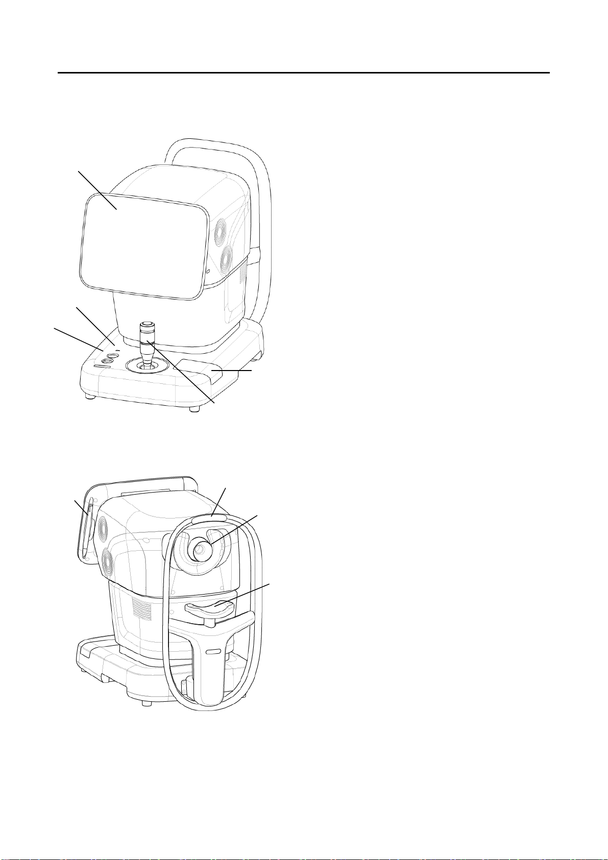
2.1 Physician's side
(1) LCD and touch panel
Displays the data or used to perform operations.
The display angle can be adjusted.
(2) Power lamp
(3) Chin rest up/down button
(4) Joystick
Moves the head in all directions. A
measurement button is provided on the top.
(5) Built-in printer
2.2 Patient's side
(1) Measurement window
(2) Chin rest
(3) Forehead pad
(4) Touch pen
The touch pen holder is a magnet type.
(1)
(2)
(3)
(4)
(Fig. 1)
(Fig. 1)
(1)
(2)
(3)
(4)
(5)
■
2-2
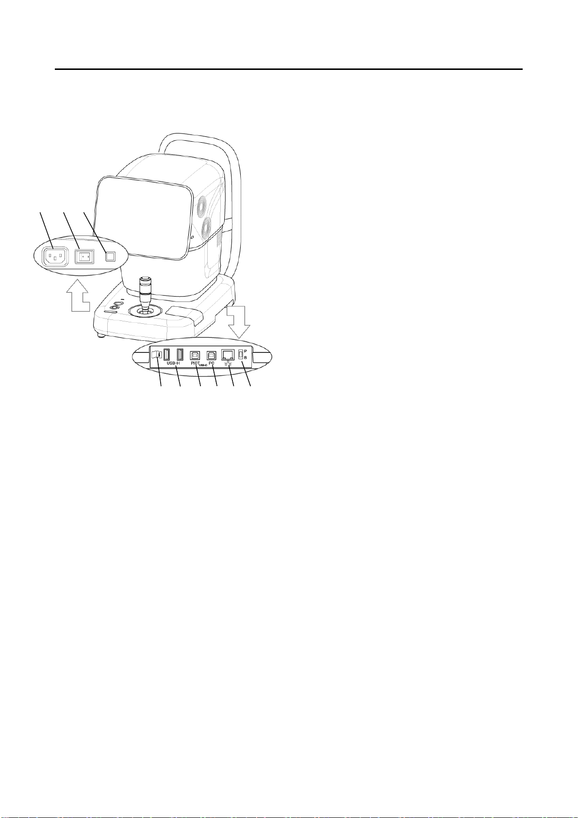
2.3 Sides of the main unit
(1) Power socket
(2) Power switch
(3) Packing button
Pressing this button for 3 seconds moves the
head to a set position in preparation for
packing.
(4) SD card slot
(5) USB-H connector
Connector for measurement unit, USB flash
memory, and external ID input device
(6) USB-D connector (PICT)
Connect the PictBridge printer here.
(7) USB-D connector (PC)
Connect the personal computer, etc. here.
(8) LAN connector
(9) Maintenance switch
Our service personnel use this switch for
maintenance. Do not change the setting.
(1) (2) (3)
(4) (8)
(5) (6) (9)
(Fig. 1)
(7)
Table of contents
Other Tomey Medical Equipment manuals

Tomey
Tomey TCP-2000 User manual

Tomey
Tomey MR-6000 User manual

Tomey
Tomey TSL-4000Z User manual

Tomey
Tomey CASIA2 User manual

Tomey
Tomey TL-100 User manual

Tomey
Tomey AL-2000 User manual

Tomey
Tomey SP-100 User manual

Tomey
Tomey Z Series User manual

Tomey
Tomey H Series User manual

Tomey
Tomey TCP-2000P User manual


