SpaceLas PT-40K User manual

Scanner Set
USER MANUAL
please read this manual carefully before your install the scanners!
Thank you very much for choosingour product ,if you have any question,please
send email to me.
MODEL:PT-40K

Page 2 of 6
Checking Parts
Please make sure the following parts are included:
2 Scanners
2 Driver board
2 Replacement mirrors
1 Scanne mount
1 power supply(PUS)
2 Cables driver to scanner
2 Cables driver to PUS
1 User manual
Introduction
The 40K is a fast and versatile galvo scan system, based on moving magnet galvanometers,
with a small and rugged dual channel closed loop diver . The system runs at pretty low voltage,
and can be implemented in almost any existing or new application. With it's driving speed of up
to 60k with the ILDA test pattern, displayed at an angle of 4-5 .
The standard delivery package contains driver , power supply and input cable .The driver
is presetted to the included galvos, but has to be retuned slightly before first use. This can be done
by using the three adjustment trimmers on the driecard. Please note, that the galvos are not set for
maximum speed at small scan angle, but set to a usable angle of 20 at 38Kpps.
The cable
High speed galvanometers demand forspecial cables, which are shielded an separated between
motor and position detector. Cable lengths up to 100cm are allowed. We recommend a cable
length of maximum 50cm.
Power source
Power source is not very critical and has minor influence on speed and quality of the complete
scanner system .Even if a standard transformer with a bridge and caps will do, We
recommends a stabilized or switched power supply. The driver board is able to run between +/-
24VDC to +/-28VDC, at 1A each. Recommended power supply is the PSU with 2x24VDC.
If you use transformer andbridge, then make sure to have minimum 10,000 uFcaps per voltage,
better 40,000 uF, parallel with a 100uF for fast peaks. Do not use extra capacitors at switching
power supplies.
Polaritiy of connecting power tothe driver is important. No warranty if connected incorrect.
The measuring procedure
The 40K was measured with Mamba Black with USB-Box, running at the desired output
speed, using the standard ILDA test pattern. Laboratory power supply at +/-24VDC, room
temperature. Windows PC with Mamba Black , 12/30k ILDAtestframe. It was also tested
afterwards with pangolinLD2000, running thesame test pattern. 5x10x0.7mm mirrorwas used
during measuring period. Tests showed a slight decrease of performance at about 5 by using a
larger 6x11x0.7mm mirror. The galvos where fixed in the standard mounts on an aluminum
baseplate, no forced cooling.
USER MANUAL:PT-40K Scanner Set Date:03/2009
Page 3 of 6
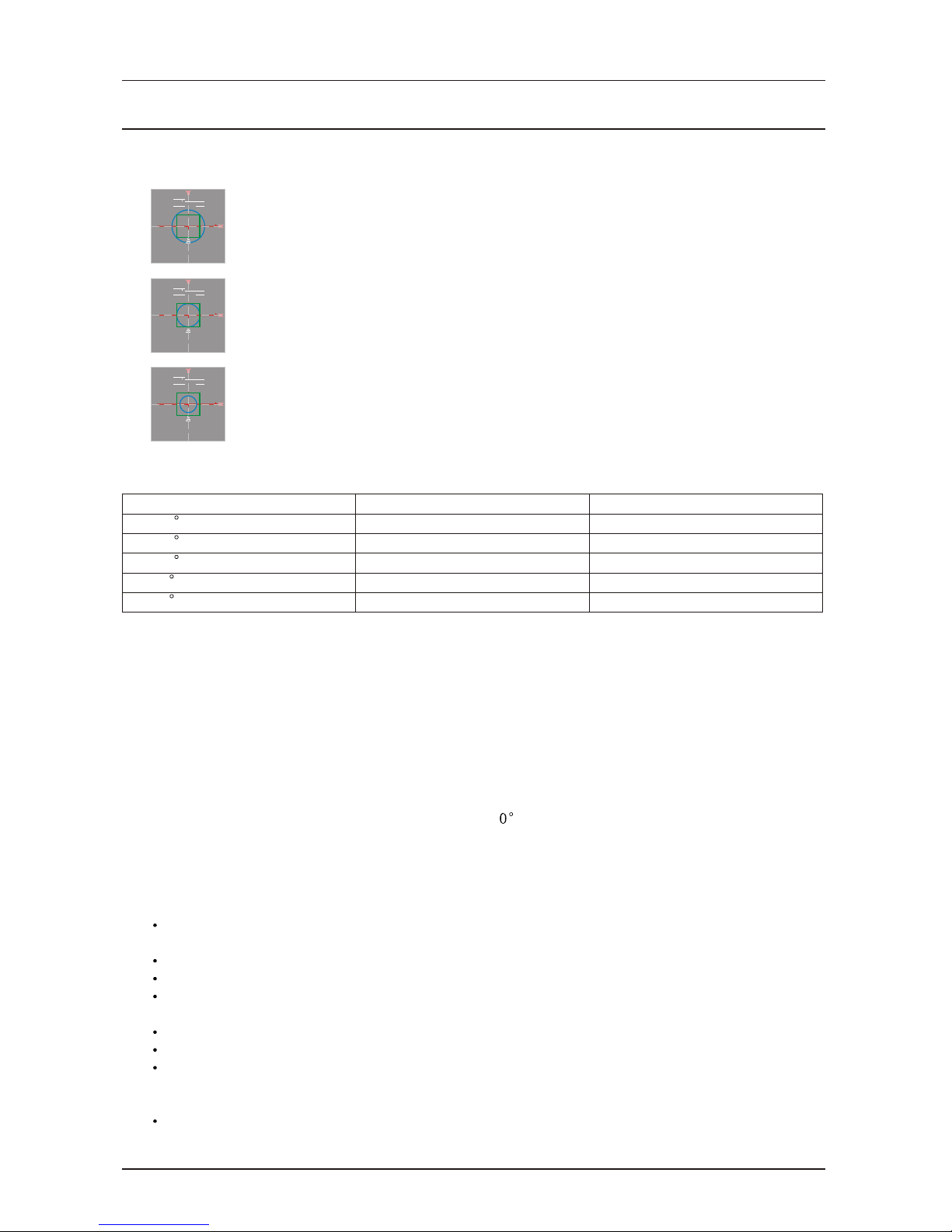
The ILDAstandard
Driver is set too fast or output speed of computer is too slow . The inner
circle is larger than the green square .
Driver and output speed matches together .
Driver is too slow or output speed of computer is too high . Readjust driver
or slow down computer .
12/30K ILDA
12/30K
12/30K
ILDA
ILDA
Deflection angle
20 optical deflection
15 optical deflection
10 optical deflection
8 optical deflection
5 optical deflection
Operating voltage
+/-24V
+/-24V
+/-24V
+/-24V
+/-24V
Speed
>38.000 pps
>40.000 pps
>45.000 pps
>50.000 pps
>60.000 pps
Adjustments
Standard configuration shows7 adjustment pots , 4 of them are necessary for the user . 3 of them
should not be changed in setting . These are necessary for linearity and other galvo specific
settings .
Basic adjustments
The driver board comes already pre adjusted for 3 projection angle and needs to be set up for
the galvo only in small areas. Every galvo is different, so 3 of them adjustments are needed. For
this, the ILDA test pattern is used ,also a setup of the galvos in XY with a laser . If you need to
ture the driver faster to smaller angles, follow the procedure below . Also if the driver is totally
deadjusted , this will be the procedure to retune it :
Size, Servo-Gain, Damping und HF-Damping are adjusted counter clockwise to their left zero
position. Now turnLFD 5 full rounds clockwise to right.
Connect computer with ILDAtest pattern, run it at approx. 20kpps.
Power on the amplifiers.
Slowly open the servo gain (clockwise). The mirror of the galvo should move now to its middle
position. If yes, turn two rounds clockwise.
Slowly open the size until you see the galvo moving.
Increase servo gain until you see overshoots. Correct itwith LFD.
Decrease undershoots byopening the HFD pot slightliy clockwise. Removegain/LFD
procedure and correct with HFD, until you the picture looks satisfying. Carefully fine tune the
driver. The better your fine tuning is, the faster is the scanspeed.
Increase speed of test patterns and readjust for optimized picture.
USER MANUAL:PT-40K Scanner Set Date:03/2009

Page 4 of 6
On each pin connector, all necessary in and outputs are available. Here is the power supply
connected, We recommend a ground free operation berween computer and drivers.
Important hints
Do not remove the driver board from its mounting bracket. This additional metal plate is
needed for groundand inereases stability of the driver. The bracket is isolated from ground.
Do not use cheap and unshielded cable. We recommend to use the SpaceLas only with SpaceLas
cables.These cables are tested and designed for this driver. We do not offer any warranty, if
other cables are used.
If the galvos gets very hot (above 45 /115 F), switch off the system and check for errors
of problems.Use approbriate heatsink for the galvos. Do NOT run them without heatsink!!
If the fuses blow continously, do not replace them with a higher valus. Check for possible errors.
The maximum current per phase should be in average below 700mA. If it is higher, there can be
a problem,which can result in overheating the galvos.
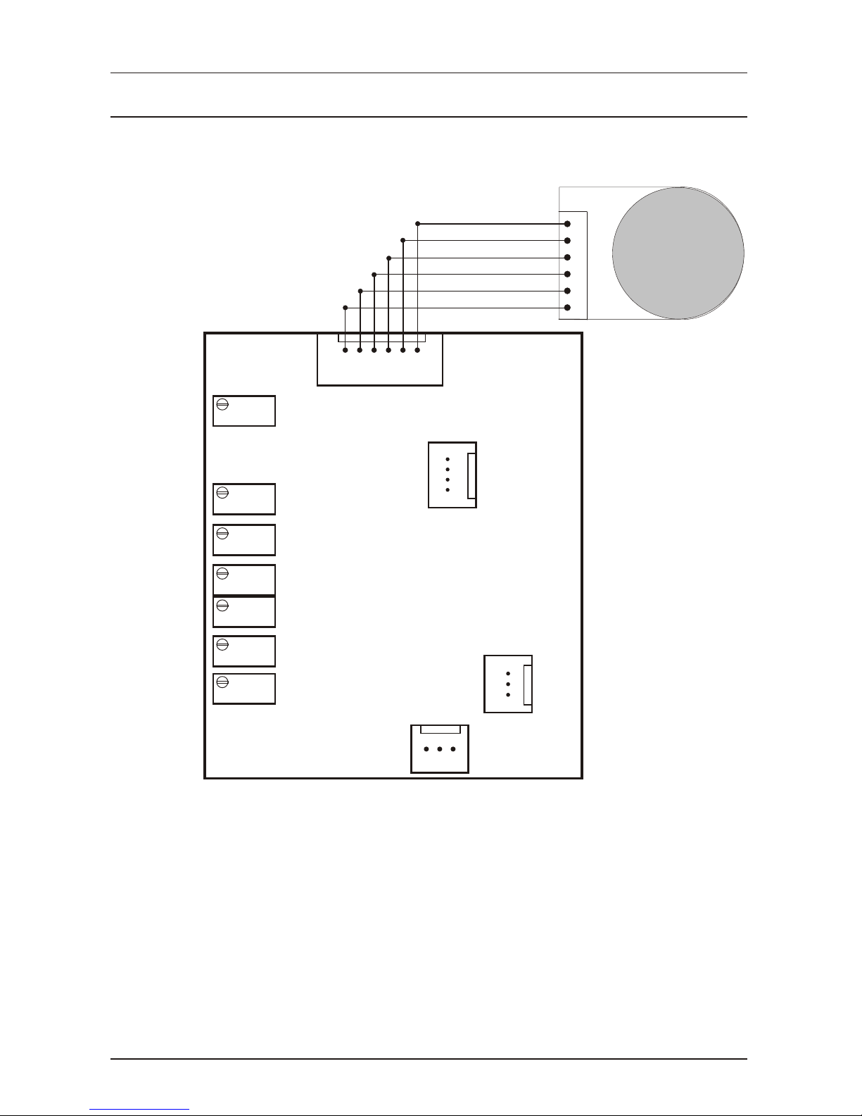
In / Outputs
Connecting the dual channel driver
Each channel of the driver must be connected to the power supply and to the signal source. Both
4pin connectors show equal pinning. Connect both channels +24VDC to the positive 24VDC
coming from the power supply, also the -24VDC to the negative source from the power supply.
Use only one ground pin of each connector to connect to the GND of power supply.
PIN Layout Switch Power Supply
Input 85-260 VAC, Imax 1.5A
L N
-24V 0V +24V
USER MANUAL:PT-40K Scanner Set Date:03/2009
Legend:
Offset: Electrical offset of the driver, not the galvo! Is adjusted in factory.
HFD: HighFrequency Damping. Corrects undershoots
LFD: LowFrequency Damping Corrects overshoots.
Servo: Servo-Gain. Power of the feedback signal for the internal PID controller.
Size: Increases or decreases input sensitivity of the complete driver. Does not change driver
settings.
Position Scale:factory Setting.
Lineartity:factory Setting.
Mot+ Mot- 0V AGC PDB PDAMot+ Mot- 0V AGC PDB PDA
Driver Output
PDA PDB AGC 0V - +
Power In
-24V 0V 0V +24V
Power Out
-15V 0V +15V
Signal In
+ - 0V
Size
Servo
LFD
HFD
Position Scale
Lineartity
Offset
Page 5 of 6
USER MANUAL:PT-40K Scanner Set Date:03/2009

USER MANUAL:PT-40K Scanner Set Date:03/2009
Driver board
Scanne mount
Page 6 of 6
Table of contents


