Hybrid+ CM3UFX User manual

3+1 CHANNEL DJ CLUB MIXER
CM3UFX
ENGLISH
WITH DSP EFFECTS

PAGE 2

CM3UFX - CLUB SERIES PROFESSIONAL MIXERS
PAGE 3
OPERATION MANUAL
Dear customer,
Congratulations on the purchase of this quality mixing desk. To meet your requirements, this unit has been designed and built to
the highest standards, so that we can assure you that you have made a good and satisfying investment. To take full advantage of all
possibilities and for your own safety and the safety of your environment, please read these operating instructions carefully before you
start using the unit.
The CM3U FX 3+1 Channel DJ Mixer with DSP effects is a DJ mixing console with 1 microphone input, 3 stereo inputs, full channel
EQ’s and balanced master output plus a DJ-specific DSP effects processor, which makes this unit a very versatile choice in any
1. Read this manual completely before using the product.
2. Keep this manual in your records for future reference.
3. Follow all instruction printed in this manual, otherwise warranty may be void.
4. Follow all printed security advice on the product itself. The lighting flash with arrowhead within an equilateral
triangle makes you aware of non-insulated AC mains voltage inside the unit. The exclamation mark within
an equilateral triangle makes you aware of important operating and maintenance instructions in the
literature attached to this product.
5. Take care of enough distance between this product and sources of hum and noise like electric motors and
transformers.
6. Carry this product with greatest care. Punches, big forces and heavy vibration may damage this product mechanically.
7. The manufacturer takes no responsibility for injury or damage caused by not following the safety precautions and
instructions printed in this manual.
General Advice:
INTRODUCTION
PRODUCT DESCRIPTION
SECURITY ADVICE BEFORE USE
The following symbols are used to identify important safety information in this manual:
WARNING!
Hazardous voltage. Risk of severe or fatal electric shock.
DANGER!
Safety hazard. Risk of injury or death.
Warning: Read this section carefully before installing, powering, operating, cleaning or servicing this product!
WARNING!
Read manual before installation and
operation.
WARNING!
Fire hazard.

PAGE 4
1. Only connect this unit to a mains socket outlet with protective earth connection, ground-fault (earth-fault) protection
and overload protection.
2. Where the mains plug or an appliance coupler is used as a dis-connect device, the disconnect device shall remain
readily operable.
3. To pull the AC Cord out of the wall outlet or the unit’s AC socket, never pull the cable itself, but only the AC plug.
4. Disconnect the unit from AC supply by pulling the AC plug out of the wall outlet or the unit’s AC socket before any kind
of cleaning on the product. Use smooth and dry cloth only for cleaning.
Check all connection cables before reconnecting the unit.
5. Do not expose this unit to any dripping or splashing liquids, and do not place objects filled with liquids, such as vases,
on the unit. Do not operate this unit near to open water or in high humidity.
6. Choose the position of the AC cord according to the lowest risk of damage by foot steps or by squeezing it.
Take especially care of the AC cord outlet on the unit as well as the AC plug and wall outlet at the other end of the cable.
7. Do not open the unit for service purpose, as there are no user-serviceable parts inside. Warranty will be void in any case
of unauthorized service by the user or other not authorized persons.
1. Take care of not placing the unit near sources of heat (e.g. powerful amplifiers, fog machines).
2. Take always care of sufficient air convection in the unit’s environment to avoid overheating, especially when mounting
in a closed environment. Make sure air convection slots – if any - are not blocked. Do not operate this unit in
environmental temperatures exceeding 40 degrees Celsius.
3. Check the total maximum power of your AC wall outlet if you connect several units to one wall outlet and avoid
any overloading.
1. Never use any accessories or modifications not authorized by the manufacturer of this unit.
2. Choose a location for operation where the unit is protected from vibration and where a fixed mounting position
is provided.
3. Before plugging the AC cord in the wall outlet, check whether the AC mains voltage and frequency is the same as this
product is specified for. Whenever your AC plug should not match the wall outlet, contact you dealer immediately.
4. If fluids have spilled into the unit or small parts have intruded the unit, immediately switch off the unit and hand it over
to the authorized service for a security check.
5. Disconnect the unit from AC supply by pulling the AC plug out of the wall outlet or the unit’s AC socket during a
thunder-storm in order to avoid any damage on the unit due to AC voltage peaks.
6. In cause of not correct function of this unit or damaged AC cord or other damaged parts, pull immediately the AC plug
out of the wall outlet and hand the unit over to the authorized service for a security check.
7. To meet all aspects of functionality and security during mainte-nance work to be performed on this unit, all parts
should be replaced by genuine spare parts. Consequently, take care of your dealer or maintenance company to be
authorized by the manufacturer.
This unit produces and absorbs electromagnetic radiation. The strength of radiation and the sensitivity for disturbing interference
matches the CE and FCC requirements. A corresponding sign is printed on the backside of the unit. Any change or modification may affect
the behavior of the unit concerning electromagnetic radiation, with the CE requirements eventually not to be met any more.
The manufacturer takes no responsibility in this case.
This unit is immune to the presence of electromagnetic disturbances – both conducted and radiated - up to a certain level. Under peak
conditions, the unit is classified to show a “class C” performance criteria and may encounter temporary degradation or loss of function
which may need manual help to recover. In such case, disconnect the AC power from the unit and reconnect it again to recover.
This unit is build to conform to the ROHS standards and the WEEE directive 2002/96/EC of the European Parliament and of
the Council of the European Union. Under these regulations, the product shall not be discarded into regular garbage at the
end of its life, but shall be returned to authorized recycling stations.
HEALTH ADVICE
FUCTIONAL ADVICE
ENVIRONMENTAL ADVICE
PROTECTION FROM ELECTRIC SHOCK
PROTECTION FROM FIRE
PROTECTION FROM INJURY & DAMAGE

CM3UFX - CLUB SERIES PROFESSIONAL MIXERS
PAGE 5
BACK PANEL
Please check that the box contains the following items:
Main parts: 1 pcs. Main unit
1 pcs. Mains cable
1 pcs. Operation manual
If any part is missing, please contact your dealer immediately for replacement.
Warning: After unpacking, and before plugging the AC cord in the wall outlet, check whether the AC
mains voltage and frequency is the same as this product is specified for (see rear panel of product).
Whenever the specified voltage or your AC plug should not match the local conditions, do NOT plug
the AC cord into the wall outlet and contact you dealer immediately.
1. AC inlet and fuse holder. Use the supplied AC cord to connect the unit to AC mains. Make sure voltage and frequency
stated on the unit comply with your local AC supply. The fuse can be accessed by the small drawer at the AC inlet. To
change the fuse, unplug the AC cord first, pull out the fuse drawer and replace the fuse ONLY with a fuse of SAME
voltage and rating. If the fuse blows again after replacement, hand over the unit to qualified service personnel.
2. Power switch. Switches the unit on and off. Make sure to switch the unit off when not in use.
3. Main stereo output. This is a balanced stereo output carrying the main output signal controlled by (26).
4. Main stereo output. This is an unbalanced out carrying the same signal as output (3).
5. Booth stereo output. This is an unbalanced output carrying the booth signal controlled by (27). This output can be used
for a 2nd zone which needs independent volume control, such as the DJ booth or the seating area of a club.
6. Record output. This is an unbalanced stereo output carrying the same signal as the main output (3/4), but not influenced
by the main volume control (26). This is normally used for recording the output to an external tape, CD or memory device.
7. Line inputs. These RCA connectors provide inputs for line-level signals to the assigned channels.
8. Phono Inputs. Depending on the position of the selector switches (9), these RCA connectors provide the following inputs: (A)
Position “PHONO”: input for phono-level signals to the assigned channels, featuring the necessary RIAA equalization. (B) Position
“LINE”: input for line-level signals to the assigned channels. Note that if the Phono inputs are not used and the sensitivity is
switched to “PHONO”, the inputs shall be terminated with the supplied termination plugs (as factory-inserted at delivery).
9. PHONO/LINE selector switches for PHONO inputs. These switches change the sensitivity of the PHONO inputs between PHONO
(RIAA equalized) and LINE level.
10. USB input. This allows the use of the mixer’s internal soundcard by connecting a PC to the mixer through this port and routing
the audio output signal to INPUT2 by means of the top-panel selector switch (16). Please note that this is NOT a host interface with
audio decoder, so this interface is not intended to directly connect hard disks or USB sticks with audio content. This connector is
only designed to act as an external USB 1.1 soundcard, to be connected to a PC. Apart from replaying audio from the PC, this
interface is bidirectional and also allows to record the signal present at the record output (6) digitally into the PC.
UNPACKING

PAGE 6
TOP PANEL
11. Microphone input for DJ MIC (MIC1). This is a balanced Combo (XLR+TRS) connector without phantom power provision, hence only
suitable for dynamic microphones.
12. Channel Equalizer. Allows the adjustment of the tonal balance for each of the inputs. For the microphone inputs adjustment is
provided in two voice-specific frequency bands with an adjustment range of ±12dB; for the stereo channels, adjustment is provided
in three music-specific frequency bands with an adjustment range of -26/+12dB, thus providing a virtual “kill” function for each
frequency band if set to extreme attenuation.
13. Microphone level control. Sets the microphone level, provided that the microphone is switched on by means of switch (14).
14. On/Off (ON AIR) switch for the DJ MIC (MIC1) microphone.
15. Input level meter for display of the input signal level.
16. Input selector for stereo channels. Switches between the inputs as indicated on the front panel. A LED indicates the pressed
position.
17. Gain control of input channels. Allows adjustment of the input sensitivity to compensate for different source volumes. To facilitate
proper setting of input gain levels, the stereo inputs INPUT1/2/3/4 feature a 10-LED level meter.
18. CUE switch for stereo channels. Assigns the respective channel to the headphone bus for pre-fader-listening (CUE). A LED i
ndicates the pressed position.
19. Channel fader for input channels. A high-grade dual rail 60mm fader determines the volume of the respective channel.
20. Crossfader. A high-grade dual rail 45mm fader determines the mix ratio between the stereo signals of channel 1 and channel 3.
21. Crossfader Curve switch. Allows the transition characteristic of the crossfader between the CH1 and CH3 signal to be switches
between smooth a flat and steep mixing curve.
22. Headphones output. A ¼” TRS connector to connect a headphone. Turn the CUE level (25) down before plugging in any headphones.
23. CUE Mode switch. This control offers two pre-listening modes: (A) Split. In this mode, the master signal appears on one earcup of
the headphones, the CUE signal on the other earcup. (B) Blend. In this mode, main and CUE signal are mixed with
adjustable ration
by means of control (24). A LED indicates the pressed position.
24. CUE Mix control. If the CUE mode (23) is set to “BLEND”, the headphone signal can be a mix of the main output and the input(s)
assigned to the CUE bus by means of switches (18). This control determines the mix ratio between the main and the CUE signal.
11 15 16 17 29
12
13
14
18
19
21 20
22
28
27
26
25
24
23
30
31
32
33
34
35
37
38
36

CM3UFX - CLUB SERIES PROFESSIONAL MIXERS
PAGE 7
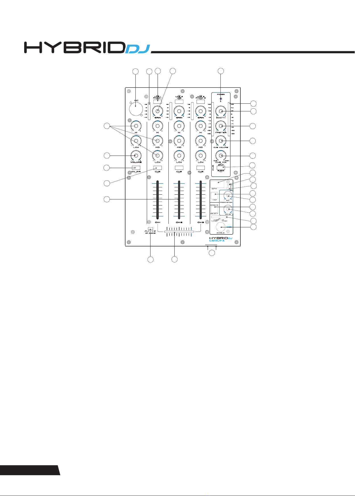
25. CUE volume. Determines the signal volume at the headphone output (22). Always set this control to minimum before putting on
headphones, as sudden high-volume impact may damage your ears. See further health advice below.
26. Output level control. Determines the main output level present at outputs (3) and (4).
27. Booth level control. Determines the booth output level present at output (5).
28. Output level meter. Displays the output level at outputs (3) and (4).
29. Power LED. Indicates the on/off status of unit.
CONNECTIONS
For connecting this unit to AC mains, please note:
1. Check whether the AC mains voltage and frequency is the same as this product is specified for (see rear panel of product).
Whenever the specified voltage or your AC plug should not match the local conditions, do NOT plug the AC cord into the wall outlet
and contact you dealer immediately.
2. Do not operate this unit without the line cord earth ground connected. To do so may increase the risk of electric shock and increase
line cord conducted emissions.
For making audio signal connections, always remember that good and reliable connections are a basic requirement for good sound and
reliable operation. Bad soldering of cables can result in intermittent audio signals or temporarily lost ground connections, hence always
use good cables. In case of doubt about making proper connections, please see check the standard pin assignments required for proper
operation in the appendix of this manual.
It is also essential that high-gain inputs are terminated properly to avoid excess noise contribution. Specifically, this applies to the
PHONO inputs. If these inputs are not used and the sensitivity is switched to “PHONO”, the inputs shall be terminated with the supplied
termination plugs (as factory-inserted at delivery).
EFFECTS SECTION
30. BPM display. Displays the BPM value of the current music signal played through the main output. The BPM display will show “ - - -
. – “ if the music signal has not enough sensible rhythmic content to automatically determine a BPM value. In such case, wait unit
the enough rhythmic content becomes available, or use the manual tap mode by means of the TAP button (31).
31. TAP button. This button allows to determine a BPM value manually. If the music signal has a rhythmic structure too complex or
not determined by percussive sounds, the automatic BPM counter may not be able to derive a sensible result and will display “
- - - . – “ on the display (32). In this case, you can use the Tap button to tap along the music; after 4 taps, the display (32) will show
the average speed of your tapping in BPM. The longer you tap, the more precise the result will get due to build-in averaging. Once
you stop tapping, the last result remains displayed on (30). If you wish to switch back to automatic mode, just press the Tap button
once. Whether in automatic or manual mode, the tap button will flash with the speed of the displayed value in (30).
32. SYNC LED. This LED indicates whether the time base of the chosen effect (where applicable) is in synchronization with the BPM
value displayed in (30). In this case, the LED is fully lit. If the time base of the chosen effect (where applicable) is based on the
value shown in the display (30) but has been modified by means of the RATE control (34), the LED will flash. If the time base of the
chosen effect (where applicable) is not related to the displayed value in (30), but based on a default 120 BPM time base, the LED
will be off. The default status (upon start-up) is off (time base = 120 BPM).
33. SYNC Switch. This switch allows to synchronize the time base of the effect (where applicable) with the BPM value displayed in
(30), independent of whether such value has been derived automatically or by manual tapping with (33). After start-up, the unit is
in not-synchronized mode, which means all effect time bases (where applicable) are set to a default of 120 BPM. Pressing the
SYNC switch once will synchronize the effects’ time base (where applicable) to the displayed BPM in (30), and the SYNC LED (32)
will be lit. Pressing the SYNC switch again will switch back the effect time base to 120BPM. In case the synchronization is active
and the SYNC LED is lit, the user may vary the time base of the effect by turning the RATE control (34), where the displayed BPM-t
ime base will be prorated accordingly. This deviation from the synchronized time base will be visible by the SYNC LED flashing.
Pressing the SYNC switch once when the SYNC LED is flashing will reset the time base to the display BOM value in (30).
34. RATE/(FREQUENCY) control. Allows to change the speed rate with or without BPM synchronization, or the effect frequency
(depending on the chosen effect, see below).
35. INTENSITY/(MIX) control. Allow to set an intensity parameter for the effect, or (depending in the chosen effect, see below) the
setting of the dry/wet mix ration between effect and original signal.
36. Effect selector switch. This switch allows to consecutively step through the five provided effects. The selected effect is indicated by
the LEDs in the selection bargraph (37). The effects available are listed at the end of this chapter.
37. Effects selection bargraph. Indicates which effect is selected. Please note that once the chose effect is changed, the last setting
of the Rate/(Frequency) control (34) is stored and will be recalled whenever returning to this effect; however, the Intensity/(Mix)
parameter is a global setting and will not be stored with the effects.
38. Effects ON/OFF switch. Activates the effect which is chosen by (36). Once the effect is active, this switch is backlit.

PAGE 8
MAINTENANCE AND WARRANTY
While we have chosen the best components to make this product as rugged and reliable as possible, some parts in audio products
(potentiometers, faders, switches) are subject to wear which is a matter of operation cycles, and not of time. While providing a full
time-based warranty according to the country’s of purchase requirements on the function of the electronic circuitry, we hence have to
limit the warranty on such electro-mechanical parts to 90 days from the date of purchase.
In many cases, malfunction of electro-mechanical parts occurs due to dust contamination, which may require cleaning of such parts.
As the inside of such parts is not accessible, a common practice is to use cleaning fluids in the shape of sprays. Please be reminded
that many of such fluids contain chemicals which may wash away the dust but at the same time corrode or damage contact surface and
may cause cosmetic damage to other parts. We hence explicitly exclude any claims for exchange of damaged part due to mechanical or
chemical impact.
Without liability, we recommend CaiLube MCL fader cleaner and lubricant available from CAIG Laboratories if the need of cleaning for
electro-mechanical parts occurs.
Further to that, this unit does not need regular maintenance. The internal electronics are protected by a 5x20mm fuse. The fuse can
be accessed by the small drawer at the AC inlet. To change the fuse, unplug the AC cord first, pull out the fuse drawer and replace the
fuse ONLY with a fuse of SAME voltage and rating. If the fuse blows again after replacement, hand over the unit to qualified service
personnel.
POWERING UP
Following a proper power-up sequence protects your equipment – specifically speakers – and your ears. Follow the below procedure:
1. Turn down all output volume controls of any equipment in your audio system.
2. Switch on your audio sources first (Turntables, CD Players, PC’s with soundcards, Tapedecks, etc.)
3. Switch on the audio mixer
4. Switch on any audio processor between the mixer and the amplifier(s) [if any].
5. Switch on the amplifier(s).
6. Turn up the audio level on your sources if such controls are provided.
7. Set the audio output of your mixer to a low level.
8. Set the audio output of any audio processor between the mixer and the amplifier(s) to a medium level [if any such processors].
9. Turn up the volume controls of your amplifier(s) slowly.
10. Make adjustments to all volume settings as needed.
For switching off, follow the inverse sequence – always switch off your amplifier(s) first, then any processors between mixer and
amplifier(s), then the mixer, then the sources.
OPERATION
Apart from using good equipment, good sound comes from using it correctly. Level setting mistakes are one of the common reasons
why even good equipment may not perform as desired. For setting levels, please be reminded that two guidelines need to be followed:
1. Avoid distortion by leaving some headroom. Never overrun any audio-equipment’s inputs. Level meters and displays allow you to
make sure that signals do not enter critical levels.
2. Avoid unnecessary amplification by using as little attenuation as possible. For example, if you turn down the input gain of a mixer
to minimum, and then increase the main output of the mixer to maximum to drive your amplifier properly, you will create unnecessary
noise, as you first dispose of some already existing signal level, and then later apply amplification (tainted with noise) to make it up.
Obviously, these two requirements are marking a levelling window that the operator must match to achieve a good sound with as little
distortion and noise as possible.
DANGER: Excessive volume levels on headphones or other sound systems may cause hearing damage.
Always turn the volume control to minimum when you switch the unit on, and do not exceed healthy
listening levels.

CM3UFX - CLUB SERIES PROFESSIONAL MIXERS
PAGE 9
Mains Input EU version:
Mains Input US version:
Power consumption:
Frequency response:
S/N:
THD+N:
Dimensions:
Weight:
AC220-250V~ 50Hz
AC110-120V~ 60Hz
max. 16W
20Hz-20kHz ±1.0 dBu
>82dB
< 0.07% @ 1kHz
W 214× H294x D 104mm (85mm mounting depth)
2.4 kg
Standards
EU safety:
EU EMC:
US safety:
US EMC:
EN 60065:2001 +A1
EN55103-1:1997, EN55103-2: 1997
UL60065
FCC Part 15
This product meets both the EMC Directive 2004/108/EC and the Low Voltage Directive 2006/95/EC.
For further information ask your dealer or visit the website of the manufacturer.
TECHNICAL DATA

www.vivaafrika.co.za
DJ MIXERS
CLUB SERIES PROFESSIONAL
Table of contents
Other Hybrid+ Dj Equipment manuals

Hybrid+
Hybrid+ HMH GOBO II User manual

Hybrid+
Hybrid+ HMH100B User manual

Hybrid+
Hybrid+ MUSHROOM User manual

Hybrid+
Hybrid+ TRIPLE DERBY User manual

Hybrid+
Hybrid+ HMH 7 User manual

Hybrid+
Hybrid+ HMH 12 User manual

Hybrid+
Hybrid+ FOUR BEAM User manual

Hybrid+
Hybrid+ HMH 230 User manual

Hybrid+
Hybrid+ DMX-384 User manual

Hybrid+
Hybrid+ HH3000 User manual