Spanbilt Fasttrak WorkShop 2010 User manual
NOTES
THE MANUFACTURERS CANNOT BE HELD RESPONSIBLE FOR ANY CONSEQUENCES DUE TO SHEDS THAT ARE NOT
INSTALLED PER INSTRUCTIONS OR FOR DAMAGE DUE TO WEATHER CONDITIONS, ACTS OF GOD OR FOR SHEDS THAT
ARE LEFT PARTIALLY ASSEMBLED OVERNIGHT. PARTS MAY CONTAIN SHARP EDGES & CORNERS. CARE MUST BE TAKEN
WHEN HANDLING VARIOUS PIECES TO AVOID A MISHAP, FOR SAFETY SAKE, PLEASE USE A PAIR OF WORK GLOVES, EYE
PROTECTION & PROTECTIVE CLOTHING WHEN ASSEMBLING OR PERFORMING ANY MAINTENANCE ON THE BUILDING.
DO NOT ASSEMBLE IN WINDY CONDITIONS
1ST
READ INSTRUCTIONS FIRST 3 PERSON ASSEMBLY
BEFORE COMMENCING SHED ASSEMBLY, CHECK ALL PARTS. IF THERE IS A DISCREPANCY, PLEASE CALL
YARDSAVER (SEE REAR OF INSTRUCTION BOOK)
ASSEMBLY INSTRUCTIONS
WorkShop 2010
Subject to changes © Spanbild Pty. Ltd.
W5915mm x D2800mm x H2085mm
REVISION 10-03-14

Read instructions and check parts carefully
before assembling the shed.
Do not assemble in windy conditions as panels
may be difficult to handle and damage may result.
Please wear safety gloves and glasses at all
times to protect against sharp metal edges.
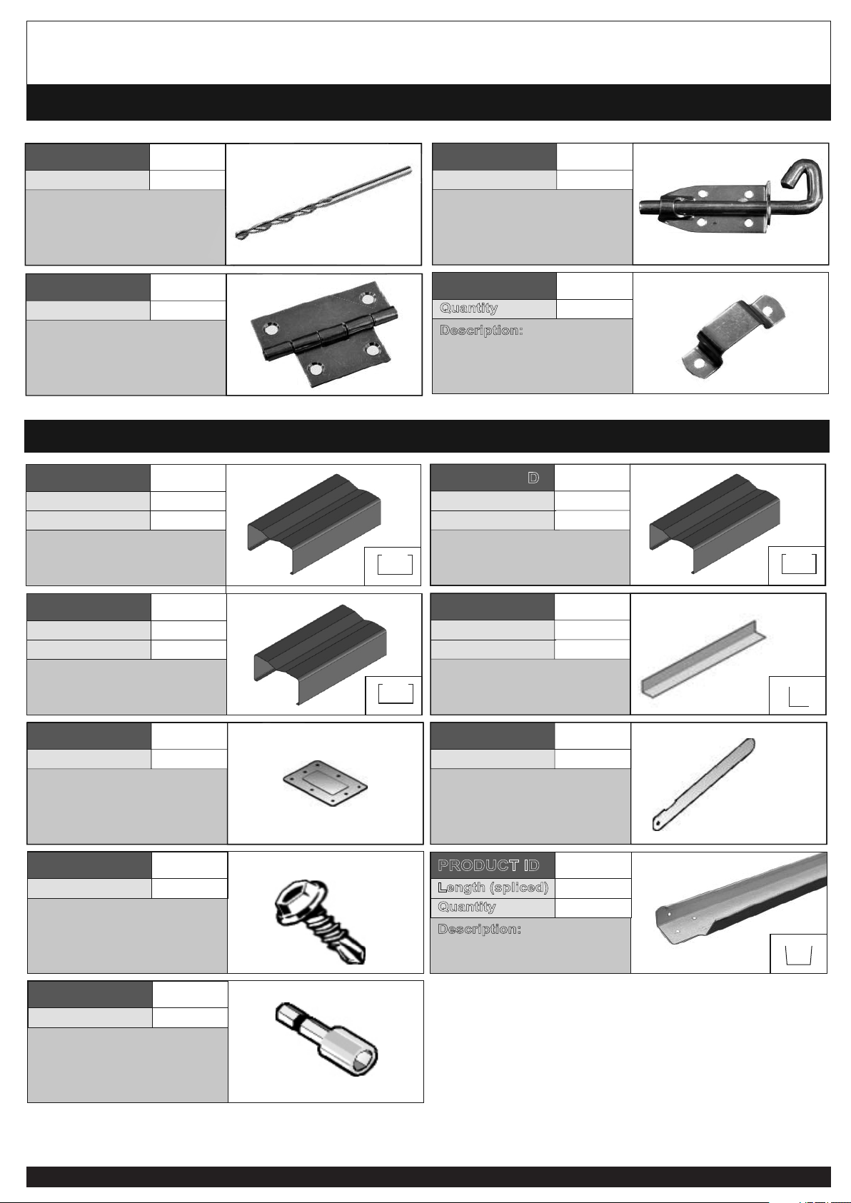
MOST PILOT HOLES ARE PRE-PUNCHED AND IN THIS CASE DRILLING
HOLES IS NOT NECESSARY, HOWEVER SOME PILOT HOLES NEED TO BE
DRILLED WITH THE INCLUDED 2.5MM DRILL BIT WHERE INDICATED
Do not back fill against the shed as this will
result in corrosion. Allow drainage from the site.
HANDY HINTS FOR CONSTRUCTION
Electric Drill Cordless Drill Screwdrivers 8mm Masonry
Drill Bit
Sturdy Ladder
(two if possible)
Gloves Rubber Mallet
Protective Eyewear
Measuring Tape
TOOLS REQUIRED
PAGE 2
Builders Pencil
Shifting Spanner Tin Snips
(some models
only)
6mm Drill Bit
PARTS LIST
Description:
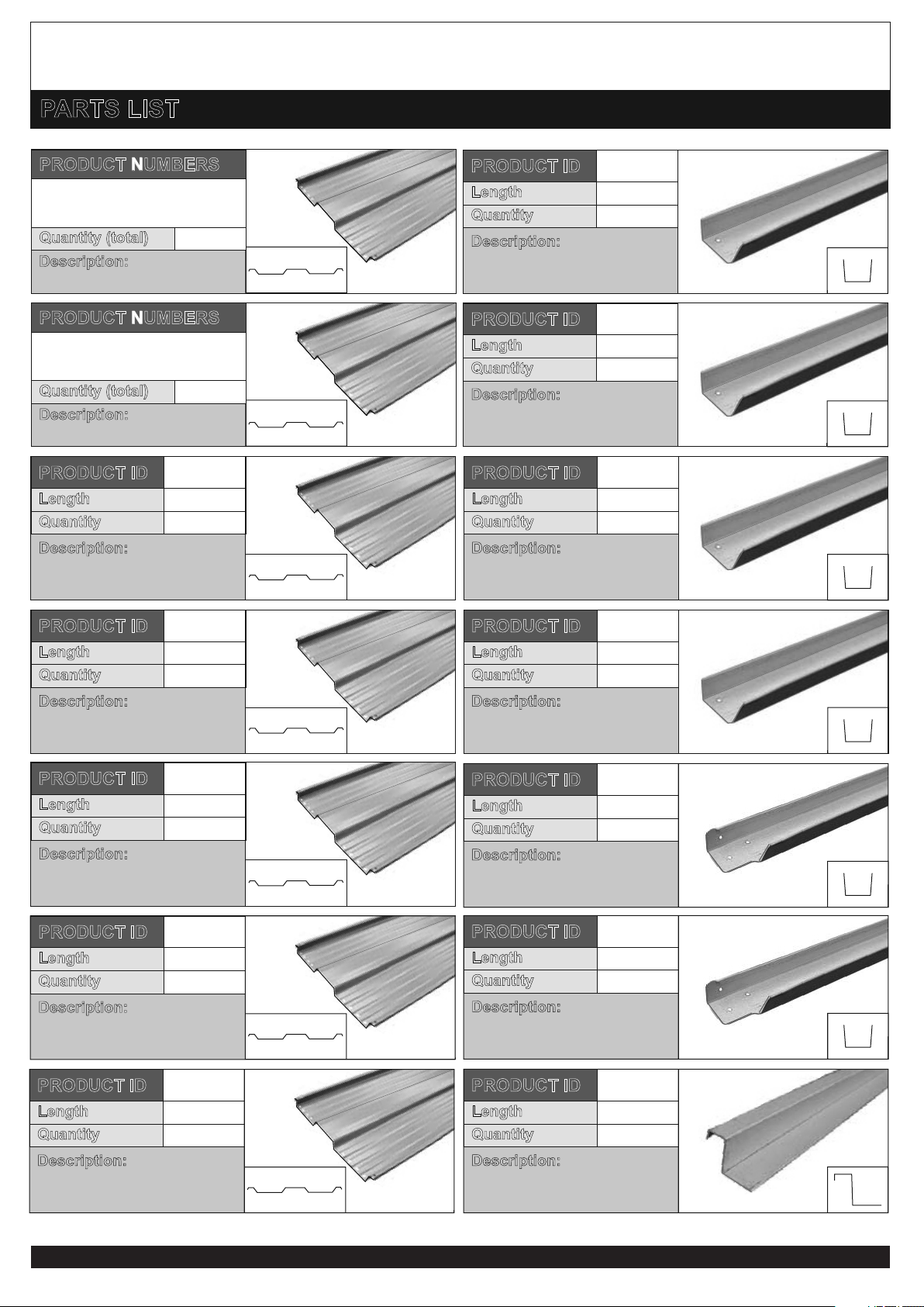
Door Panel (Partially Slit)
Length
Quantity 6
1738mm
PRODUCT ID F
Description:
Wall Panel
Length
Quantity 24
1800mm
PRODUCT ID C
Description:
Wall Corner Panels
Length
Quantity 3
1800mm
PRODUCT ID D
Description:
Roof Panels
Length
Quantity 34
1454mm
PRODUCT ID E
Description:
Gable Wall Panel
PRODUCT NUMBERS
8
Quantity (total)
B1 B2
Description:
Gable Wall Panel
PRODUCT NUMBERS
8
Quantity (total)
A2A1 A3
B3
A5A4 A6
B4 B5 B6
A8A7
B7 B8
Description:
Door Frame Top/Bottom
Length
Quantity 2
1008mm
PRODUCT ID H
Length
Quantity 6
1742mm
PRODUCT ID I
Description:
Door Frame Side
Description:
Door Boxing
Length
Quantity 6
1706mm
PRODUCT ID J
2
Description:
Door Bracing
Length
Quantity
1040mm
PRODUCT ID k
4
Description:
Door Seal
Length
Quantity 1
1706mm
PRODUCT ID L
PAGE 3
Description:
Door Panel Centre
Length
Quantity 1
1738mm
PRODUCT ID G
Description:
Door Frame Top/Bottom
Length
Quantity 4
674mm
PRODUCT ID h
2
Description:
Door Bracing
Length
Quantity
1280mm
PRODUCT ID K
2
Description:
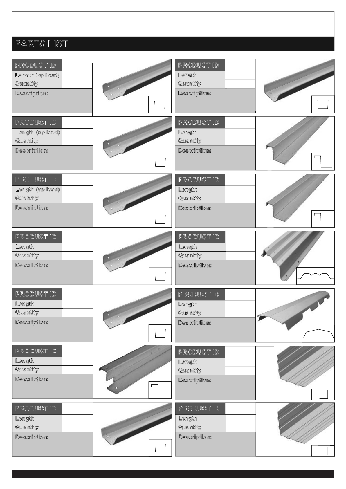
Side Channel Gable Top
Length
Quantity 2
1411mm
PRODUCT ID O
Description:
Side Channel Gable Bottom
Length (spliced)
Quantity 2 Sets
PRODUCT ID N
2921mm
=(1461 + 1460)
Description:
Top/Bottom Front/Rear
Channel
Length (spliced)
Quantity 4 Sets
3267mm
PRODUCT ID M
=(1460 + 1807)
PARTS LIST
PAGE 4
Description:
Door Jamb
Length
Quantity 4
1800mm
PRODUCT ID Q
Description:
Side Channel Gable Top
Length
Quantity 2
1415mm
PRODUCT ID P
2
Description:
Bottom Door Spacer
Length
Quantity
1367mm
PRODUCT ID R
1
Description:
Top/Bottom Front/Rear
Channel
Length (spliced)
Quantity 4 Sets
2921mm
PRODUCT ID m
=(1460 + 1461)
2
Description:
Bottom Door Spacer
Length
Quantity
1021mm
PRODUCT ID r
1
Description:
Top Door Spacer
Length
Quantity 1
1367mm
PRODUCT ID S
Description:
Ridge Cap
Length
Quantity 9
708mm
PRODUCT ID U
Description:
Ridge Beam
Length
Quantity 8
1710mm
PRODUCT ID T
Description:
Gutter Trim
Length
Quantity 4
2096mm
PRODUCT ID V
Description:
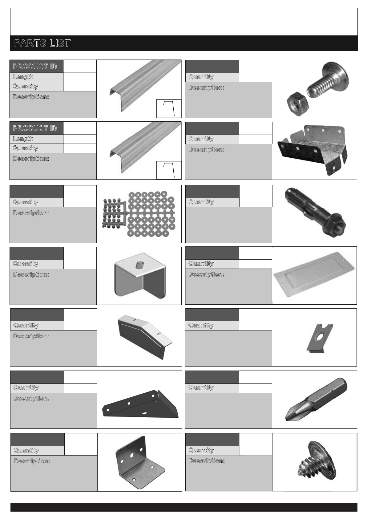
Top Door Spacer
Length
Quantity 1
1021mm
PRODUCT ID S1
Description:
Gutter Trim
Length
Quantity 2
1750mm
PRODUCT ID V1
Description:
Roof Angle Trim
Length
Quantity 2
1446mm
PRODUCT ID W
Description:
Roof Angle Trim
Length
Quantity 2
1443mm
PRODUCT ID W1
PARTS LIST
Clip Nut
Quantity 5
Description:
Nut & Bolt 3/16”
Quantity 16
Description:
Ridge Beam Bracket
Quantity 2
Masonry Anchor
Quantity 12
PAGE 5
Description:
Door Plate
Quantity 2
Description:
Plastic Washer and Screw
Cap Sheet
Quantity 3
Description:
Plastic Corner Cap
Quantity 4
Description:
Corner Bracket
Quantity 8
Description:
Plastic Ridge End Cap
Quantity 2
Description:
Quantity 12
55mm Bracket
Phillips Head Bit
Quantity 1
Description:
Self Tapping Screws - Silver
Quantity 600
PARTS LIST
PAGE 6
Description:
Hinges (offset)
Quantity 6
Quantity 1
Description:
2.5mm Drill Bit
Description:
Padbolt
Quantity 4
Description:
Keeper
Quantity 4
Description:
Portal Leg
Length (spliced)
Quantity 4
PRODUCT ID A
Description:
Roof Beam
Length (spliced)
Quantity 4
PRODUCT ID B
2
Description:
Top Gusset
Length
Quantity
1820mm
PRODUCT ID C
2
Description:
Corner Gusset
Length
Quantity 2
810mm
PRODUCT ID D
1728mm
1346mm
PORTAL FRAME - PARTS LIST
Description:
70x100 Plate
Quantity 4
Description:
Gable Gusset Strap
Quantity 2
Description:
Nut Runner
Quantity 1
Description:
Self Drilling Tek Screw
Quantity 126
(Portal)
Description:
Bracing channel
Length (spliced)
Quantity (2 x 1461 + x 1460) (2 )
2710mm
PRODUCT ID X
=(1461 + 1460)
PAGE 7
6015mm x 2900mm 12
WS 2010
Front side of shed
DEPTH
WIDTH
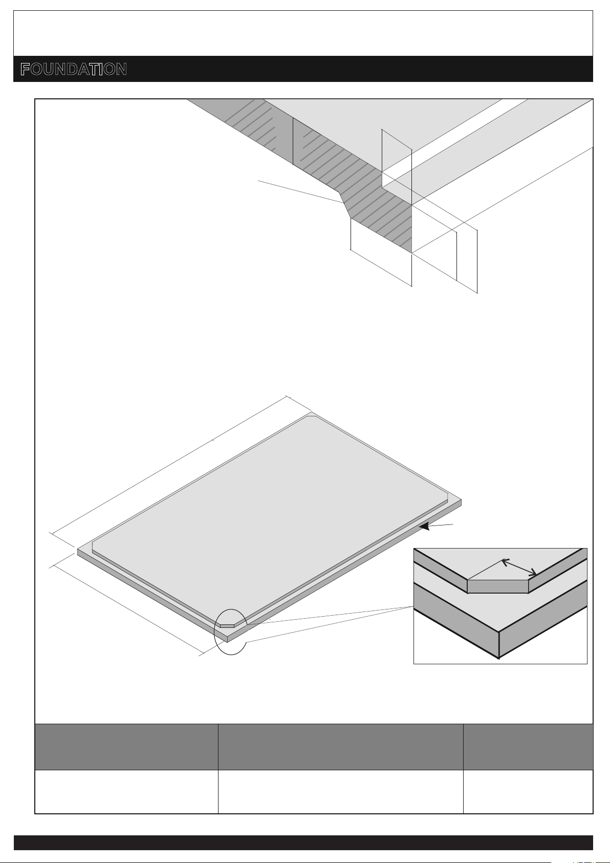
FOUNDATION
Recommended slab rebate detail
Although not required, it is strongly recommended that, to avoid water leakage around the base of your
shed, a rebate be cast into the slab. This will allow the shed to sit below the slab level and prevent water
from reaching the upper level of the slab.
130mm
150mm
75mm
150mm
75mm
Recommended
edge thickening
SHED CODE OUTER SLAB SIZE
width x depth
Slab Details
Your garden shed must be erected on a solid, level and square foundation. We strongly recommend you
pour a concrete slab 75mm thick, reinforced with SL62 mesh (minimum) using dimensions from the
table below.
*Masonry anchors are supplied*
ANCHORS
M8 x 40mm
125
If you planning a rebated slab make sure to cut the 4 corners at 125 x 45 as shown in detail
below. Also cut short the length of the portal leg by 20mm.
o
2
LEG
LEG
m
m
50
0
2
m
m
807
1
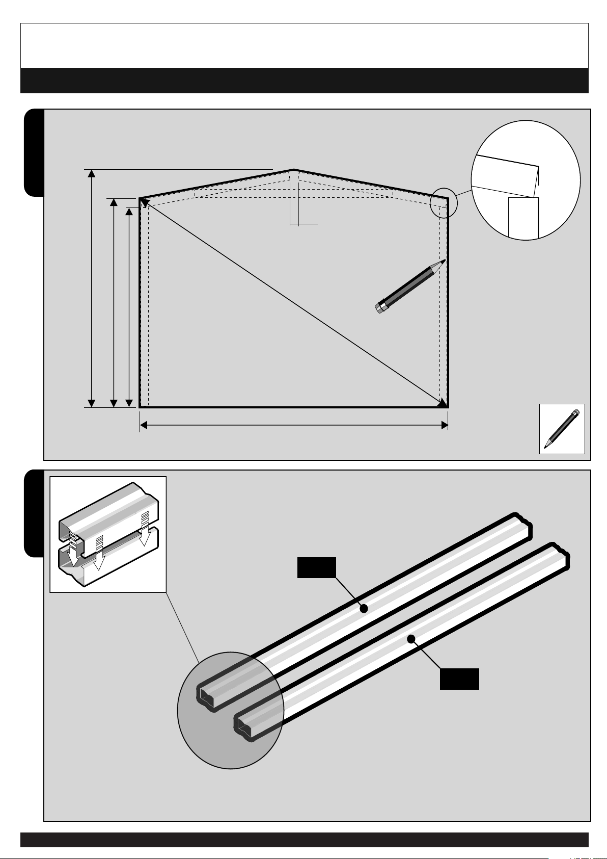
2750mm
3290mm
1
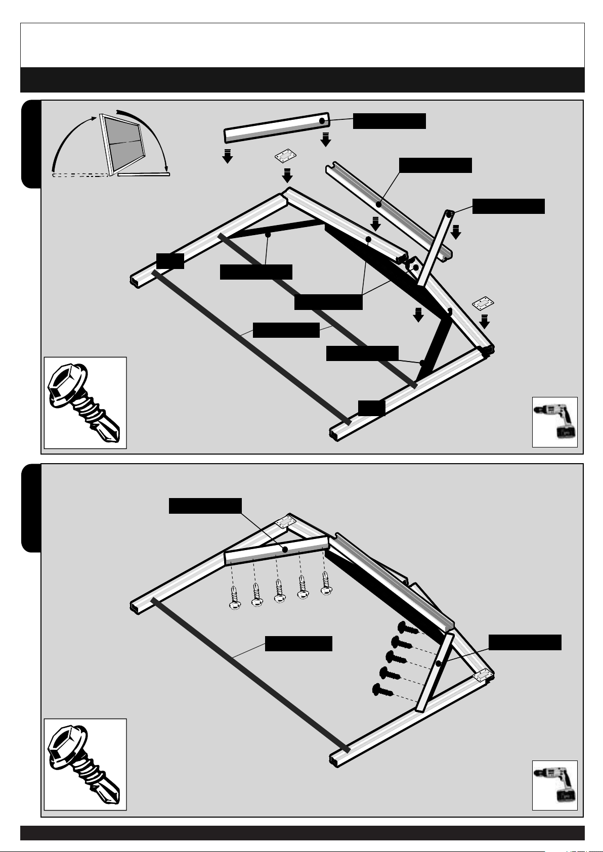
Mark out with pencil or chalk on the flat ground as shown
All four Portal Legs are required to be boxed as shown to make 2 legs
Roof beam sits
on top of leg
PORTAL FRAME ASSEMBLY
PAGE 8
All four Portal Legs are required to be boxed as shown to make 2 legs
54
m
m
725
1
Make sure to cut 20mm off, if you have a rebated slab.(L= 1708)
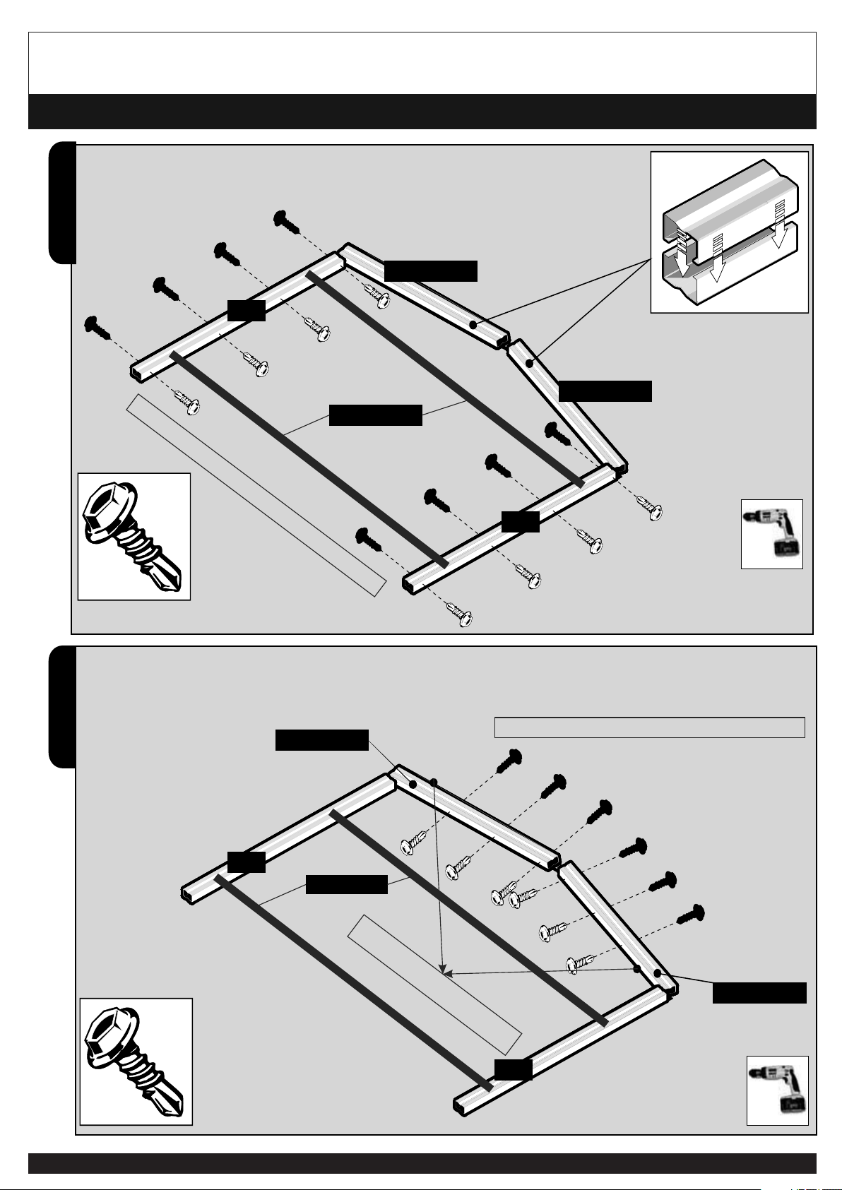
PORTAL FRAME ASSEMBLY
PAGE 9
3
4
LEG
LEG
ROOF BEAM
ROOF BEAM
ROOF BEAM
ROOF BEAM
All four Roof Beams
are required to be
boxed as shown
Screw the boxed legs together using the Tek Screws (portal)
Screw the boxed roof beams together using the Tek Screws (portal)
Screws should be through the center of the beam
First screw should be minimum 200mm
away from the outer edge.
LEG
LEG
Screws should be through the center of the beam
Bracing “X”
Use bracing channel “X” to temporarily hold it in place.
Join the bracing channels to the length of 2710mm.
Bracing “X”

PORTAL FRAME ASSEMBLY
PAGE 10
5
6
=
=
LEGLEGLEG
ROOF BEAMROOF BEAM
ROOF BEAM
ROOF BEAM
TOP GUSSETTOP GUSSET
TOP GUSSET
ROOF BEAM
ROOF BEAM
LEG
LEG
Attach the Roof Beams to
the Legs using the
100x70 Plate
Assemble, lay beams out as shown and fix first side of portal
Bracing “X”

PORTAL FRAME ASSEMBLY
PAGE 11
7
ROOF BEAM
CNR GUSSET
CNR GUSSET
LEG
LEG
ROOF BEAM
CNR GUSSET
CNR GUSSET
LEG
LEG
ROOF BEAM
Bracing “X”
PORTAL FRAME ASSEMBLY
PAGE 12
9
8
CNR GUSSET
CNR GUSSET
CNR GUSSET
CNR GUSSET
CNR GUSSET
CNR GUSSET
TOP GUSSET
LEG
LEG
ROOF BEAM
Flip portal and repeat steps 5 - 7
Join both sides of the Corner Gussets using the Portal Tek Screws, then remove the top bracing “X”.
CNR GUSSET
CNR GUSSET
ROOF BEAM
Bracing “X”
Bracing “X”

PORTAL FRAME ASSEMBLY
PAGE 13
Make sure the portals stood up properly on the slab. Out of square portal fixing may create hassle
later while panel fixing.
“SEE DETAILS ON THE NEXT PAGE”
2x2 panel door
2835mm 3180mm
Stand up the portal frame and position as per the dimension given here.
“SEE DETAILS ON THE NEXT PAGE”
Make sure the distance 3180 from the 2x2 Panel Door side edge of the slab.
Portal frame sit 75mm inside the width of the slab over the edge the edge.
It is possible to inter change the position of this door (left or right).
3 Panel Door
75mm

PORTAL FRAME ASSEMBLY
PAGE 14
50mm
50mm
50mm
50mm
Place the 55mm Bracket as shown then
fix it to the portal leg. Make sure it is
square and flat to the slab.
Now Pre drill the Dia 8mm hole to a depth
of 50mm.
Insert and tighten the masonry anchor on
all 4 brackets.
75mm
Now can remove the bracing channel “X”.

PAGE 15
Notched ends are orientated to the
both edges of the rear panel
REAR WALL PANEL
Lay the wall panels out with the large rib
overlapping the small.
1
2
Screw the wall panels in the centre
of the rib as shown.
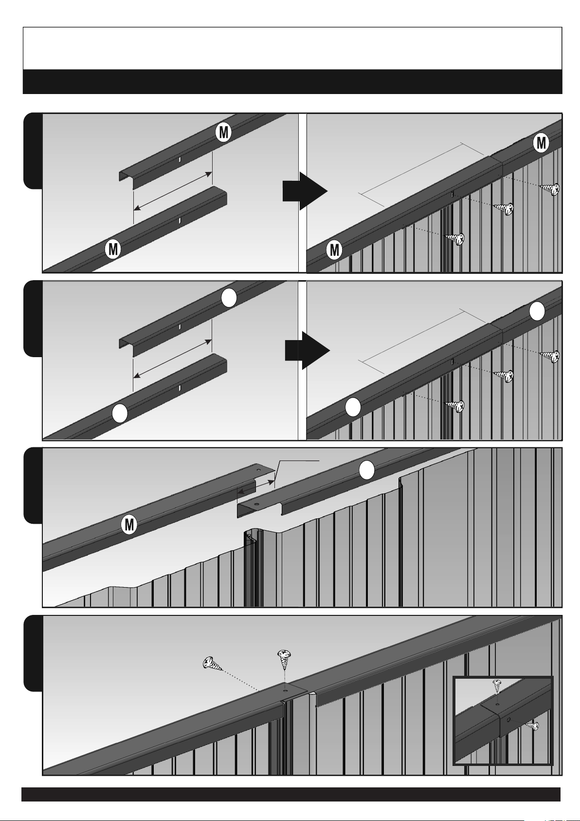
Overlap top and bottom channel by 130mm. Fit the top and bottom
channel to the wall panels. Ensure the holes in the channels are inline with
holes in the rib of the sheeting. Make sure the small flange on the
channel
positioned outside face of the sheeting.
Outside
Ensure that the small lip
of the channel is to the
outside of the shed.
Wall
Sheet
Channel
Large Rib Small Rib
“D” - Wall Corner Panel
Out side of shed
In side of Shed
Notched ends are orientated to the inside of the shed
130
15
m
m
m
m
130
Required to manipulate sheeting panel to align the channel holes
PAGE 16
REAR WALL - TOP & BOTTOM CHANNEL FIXING
1
2
1
2
Join M(1460) & M(1807) =3267
130mm
Overlap 130mm and join all the channel and
sheeting together
Join m(1461) & m(1460) =2921mm
130mm
Overlap 130mm and join all the channel and
sheeting together
Join M(3137) & m(2791) => 5930mm
Overlap 16mm so that the holes align properly.
Make sure to screw the channels through sheeting from outside.
m
m
m
m
m
3267-130 = 3137mm
130mm
Overlap
130mm
Overlap
2921-130 = 2791mm
5930 - 15 = 5915mm
15mm
Overlap

PAGE 17
FRONT WALL PANEL
2
Top and bottom door jamb connection.
QQ
MM
1
M
M
Notched ends are orientated to the
outer edges of the panel
Overlap the top and bottom channels by 130mm similarly m&m. M&M
Fit the top and bottom channel and door jambs to the wall panels. Ensure
that the positioning of large rib on the sheets are as indicated in the picture.
Also ensure the channel is flush with the edge of the sheets.
It is possible to interchange the orientation of the doors. Make sure the
Outside
Ensure that the small lip
of the channel is to the
outside of the shed.
Wall
Sheet
Channel
Large Rib Small Rib
Large Lip overlaps Small
Lip when fastening sheet
to sheet
CCC
D
MM
Large Rib
MM
CCCC C
mM1
D
Large Rib
Large Rib
“D” - Wall Corner Panel “D” - Wall Corner Panel
130
130 15
4 Sheet Gap
3 Sheet Gap
Small Rib
m
m
m
Small Rib
Small Rib
channels also oriented as per the drawing here.
M
MM
Required to manipulate sheeting panel to align the channel holes
PAGE 18
3
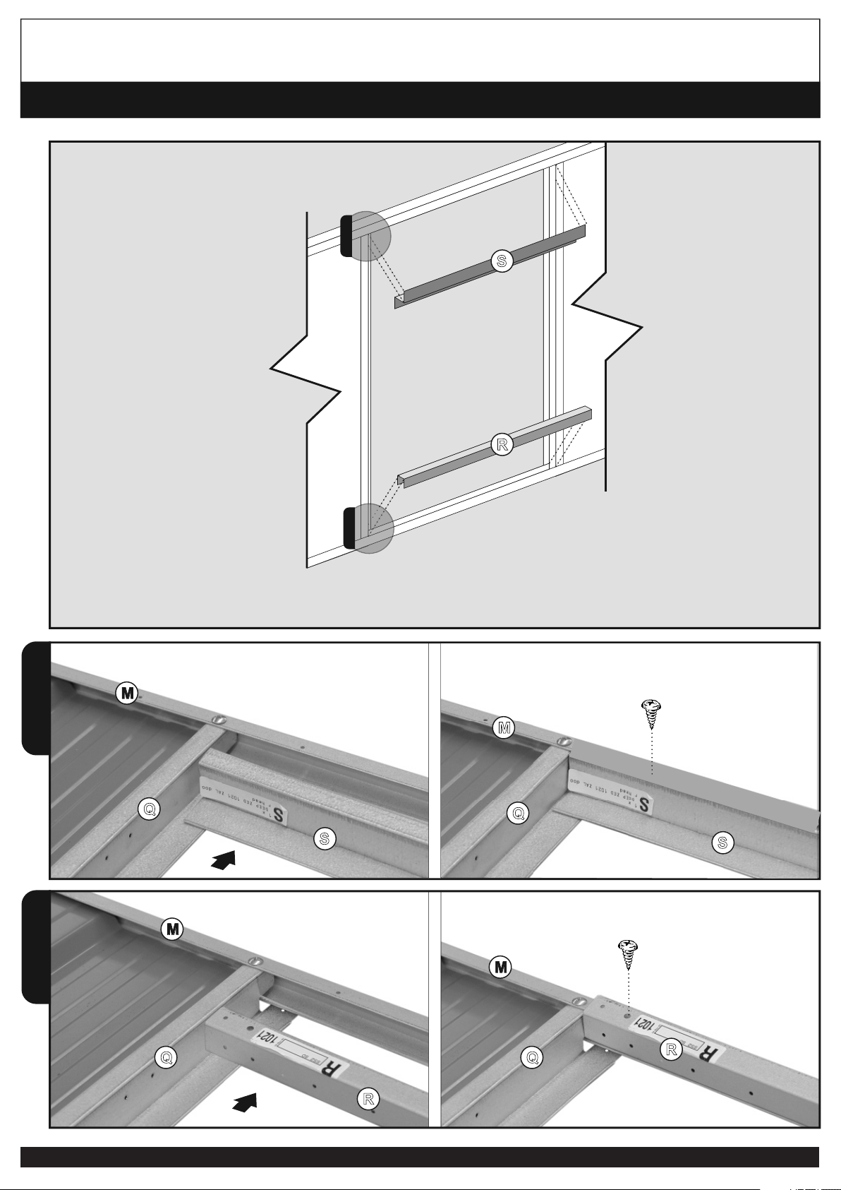
Fit the top door spacer and the bottom door spacer to the front wall panel as shown. Some pilot holes
may need to be drilled with the included 2.5mm drill bit
4
FRONT WALL PANEL- 2x2 PANEL DOOR
3
4
R
Q
S
S S
Q
M
M
R
R
Q Q
M
M
S
Q
M

PAGE 19
3
Fit the top door spacer and the bottom door spacer to the front wall panel as shown. Some pilot holes
may need to be drilled with the included 2.5mm drill bit
4
FRONT WALL PANEL- 3 PANEL DOOR
3
4
R1
Q
S1
S1 S
Q
M
M
R1
R1
Q Q
M
M
S1
Q
M

PAGE 20
FRONT WALL PANEL
Table of contents
Popular Lawn And Garden Equipment manuals by other brands


Everbloom
Everbloom Cornerstone R212421 installation guide

Krone
Krone Big Pack 890 Original operating instructions

Backyard Discovery
Backyard Discovery 14x10 BROCKTON PERGOLA Owner's manual & assembly instructions

New Holland
New Holland 790 Specifications

Miracle-Gro
Miracle-Gro Twelve Instruction guide

SGS
SGS SCT501 owner's manual

AquaCraft
AquaCraft 290100 instructions
 Operating and maintenance manual")
Max
Max PASJ30(CE) Operating and maintenance manual

hillvert
hillvert HT-ELBERT170 user manual

Worksaver
Worksaver JDBS-412 Owner's/operator's manual

Tracmaster
Tracmaster Camon LS52 Original instruction manual

Husqvarna
Husqvarna 42" Collection System Operator and parts manual