SPARLING TigermagEP FM656 Instruction manual

TM
Original Issue Date: March 2002
Revision 190101
FM657
FM656
FM626
Sanitary
FM626
FM627


TABLEOF
C
O
NTE
NTS
Page
SECTION
1 -
GENERAL
..............................
1
1.1
Measuring
System ........................................
1
1.2
Operating
Principal ........................................
1
1.3
Application
to
Magnetic
Flow
Measurement ................................................ 1
1.4
Interference ...................................................
2
1.5
SystemOperation .........................................
3
1.6
Construction ..................................................
4
1.7
Specifications ................................................
5
1.8
Interchangeability ...........................................
7
1.9
FlowRates,
Dimensions
&
Weight .................
7
SECTION
2 -
PRE-INSTALLATION
.....
10
2.1
Receiving
and
Inspection ............................
10
2.2
Storage .......................................................
10
2.3
Return
of
Equipment
....................................
10
SECTION
3 - INSTALLATION
...............
11
3.1
Application
Considerations ..........................
11
3.2
SiteSelection ...............................................
11
3.3
Rotating
the
TransmitterDisplay ..................
12
3.4
Removable
Electrodes ................................
13
3.5
Hot-Tap
Removable
Electrodes ..................
13
3.6
PipeConnections ........................................
15
3.7
Special Mounting Bolts & Gaskets ...........
16
3.8
Grounding ...................................................
20
3.9
ElectricalConnections .................................
21
3.10
Remote
Mounted
Transmitter ......................
24
3.11
Lightening
Protection ...................................
28
SECTION
4 -
START-UP
.........................
28
4.1
Start-Up
Procedure .....................................
28
SECTION
5 -
CALIBRATION
..................
28
5.1
Calibration ...................................................
28
SECTION
6 - MAINTENANCE
...............
29
SECTION
7 -
TROUBLESHOOTING
...
29
7.1
General
........................................................
29
7.2
Troubleshooting
Chart .................................
29
7.3
Electronics
SelfTest
.....................................
31
7.4
Electronics
Module
Replacement ................
31
7.5
SensorTesting ............................................
32
7.6
Coil
Continuity
Testing .................................
33
7.7
Coil
Insulation
Test
.......................................
33
Page
7.8
Electrode
Circuit
Insulation
Test ...................
33
SECTION
8 –
REPLACEMENT
PARTS
LIST ......................................................
34
APPENDIX 1-
PROGRAMMING
.........
35
1.1
General .....................................................
35
1.2
Entering
Data
.............................................
35
1.3
Batching
Modes
........................................
36
1.4
ShowMeter
Data
.......................................
36
1.5
Password
Entry
.........................................
36
1.6
RescaleRate .............................................
37
1.6.1
SelectRateUnits .......................................
37
1.6.2
SetFullScale .............................................
38
1.6.3
Select Rate as %of Full Scale ...................
38
1.7
RescaleTotal
.............................................
38
1.7.0
Lockout .....................................................
38
1.7.1
Alarms .......................................................
39
1.7.2
Count
Direction
..........................................
39
1.7.3
SelectTotal
Units
.......................................
39
1.7.4
SetRegistration .........................................
40
1.7.5
ResetTotalizer ..........................................
40
1.8
SetOutputs ...............................................
40
1.8.1
SelectPulseWidth.....................................
40
1.8.2
Backlight ...................................................
41
1.8.3
SetFlowDirection .....................................
41
1.8.4
Empty
Pipe
Detection
................................
41
1.8.5
Protocol ....................................................
41
1.9
Damping
Adjustments ..............................
42
1.9.1
Display
Damping
.......................................
42
1.9.2
Current
Damping
.......................................
42
1.9.3
Low Flow
Cutoff
........................................
42
2.0
Exit
Programming .....................................
42
2.1
Change
Password
.....................................
42
2.2
Change
Tag
...............................................
43
2.3
Diagnostics ...............................................
43
2.3.1
Check
HART
Transmission .......................
43
Check
Coil
Current .................................... 43
2.3.2
Check Current
Loop
.................................
44
2.3.3
Calibrate
4-20mA
Loop
.............................
44
2.3.4
SetFrequency ...........................................
44
2.3.5
Simulate75%
FS
.......................................
45
2.3.6
Simulator
Check ........................................
45
IDS-626/627/656/657
Page
i

TABLEOF
C
O
NTE
NTS
cont'd. APPENDIX 2 – Batch
Programming
Page Page
and
Operation
.............................
46
1.1
General .....................................................
46
1.2
Programming
............................................
46
1.2.0
Lockout .....................................................
46
1.3
Rescale
Total
.............................................
47
1.3.1
Batch
On/Off .............................................
47
1.3.2
Alarms .......................................................
47
1.3.3
Count
Direction
..........................................
47
1.3.4
Select
Total
Units
.......................................
48
1.3.5
User
Defined TotalizerUnits ......................
48
Conversion Factor ....................................
48
1.4.1
Descriptionof
Operating ...........................
49
APPENDIX3 -
Communication
......
50
1.1
RS232Sparling
Protocol
.............................
50
1.2
RS485 .........................................................
51
FIGURES
1.1
Measuring
Principal
.....................................
1
1.2
Block Diagram ............................................
3
1.3
Dimensions .................................................
8
3.1
Full
Pipe Required .....................................
11
3.2
Changing
the
Rotatable
Display ................
12
3.4
Hot Tap Electrode .....................................
13
3.5
Removing theElectrode ...........................
14
3.6
FM626
Gasket
Installation .........................
18
3.7
FM626 Sensor
Position
.............................
18
3.8
FM656
Gasket
Installation .........................
19
3.9
FM656 Sensor
Position
.............................
19
3.10
Grounding
.................................................
20
3.11
Conduit
Connections ................................
21
3.12
ElectricalConnections
I/O
PCB
.................
22
3.13
Installing
Diode
Across
Inductive
Loads .........................................
23
3.14
TigermagEP
Remote
Display ....................
24
FIGURES
cont'd.
3.15
TigermagEP
Remote
Conduit
Connections ..............................................
24
3.16
TigermagEP
Standard
Motherboard .............................................
25
3.17
Remote
Mounted
Transmitter ...................
27
4.1
Power Supply Voltage
Ratings
.................
28
7.1
AccesstoElectronics
................................
31
7.2
Removing theElectronics Module ............
31
7.3
Aligning
Electronics
Module
with
Card
Guides
.......................................
32
7.4
Replacing the E
2
PROMChip .....................
32
7.5
Coil
Resistance
Testing .............................
33
7.6
Coil
Insulation
Testing
................................
33
7.7
Electrode
Circuit
Insulation
Test ................
33
A1.1
TigermagEPDisplay .................................
35
A1.2
Main Program ...........................................
36
A1.3
Rescale RateFlow Chart ...........................
37
A1.4
RescaleTotalFlow Chart
...........................
38
A1.5
SetOutputs Flow Chart .............................
40
A1.6
Connecting
HART
Communicator .............
41
A1.7
SetDamping Flow Chart ...........................
42
A1.8
Change
Tag
...............................................
43
A1.9
Diagnostics
Flow
Chart .............................
43
A2.0
Simulate
Mode
..........................................
45
A2.1
Enclosurefor
TigermagEP
with
Batching .............................................
46
A2.2
RescaleRate
w/Batcher
Flowchart ..................................................
47
TABLES
1.
Nominal Flow Rates ......................................
7
2.
Weight ...........................................................
7
3.
Dimensions ...................................................
9
4.
Gasket
Material ...........................................
15
5.
Meter I.D. ....................................................
16
6.
Torque, Flange
&Bolt
Specifications ..............................................
17
Page ii TigermagEP™
1.3
Modbus
RTU
.. .........................................
52

1.2
1.0
Gener
al
1.1
Measuring
System
TheSparlingTigermagEPTM ModelFM-626,FM627,FM-656 andFM-657flowmetersare
obstructionless devices for monitoring the volumetric flow of conductive liquids infull closed
pipes.
Theflowmeterconsistsofasensor(waferorflanged)withanonmagnetic liner,sensing
electrodesand ameasuringtransmitter.
Operation is based on Faraday s Law of
Mag- netic Induction. An electrically
conductive liquid flowing through a magnetic
field induces avolt-
Operating
Principle age which is perpendicular to this field and to
the direction of the flow. This voltage is
proportional to theaverage flow velocity. See
Figure 1.1.
The mathematical formula describing
Faraday s lawreads:
E = B x L x V
E=Induced voltage
B=Magnetic field intensity (flux
density) L =Distance between the
electrodes
(pipe diameter)
V = Average flow velocity of
liquid
1.
3
Application
to
Magnetic
Flow
Measurement
Measuring
Principle
Figure 1.1
In a magnetic flowmeter the liquid acts as a moving conductor as it flows through the pipe. The
induced voltage (E) in the liquid is measured by two sensing electrodes mounted opposite
each other in the meter sensing head.
The length of the conductor is equal to the distance between sensing electrodes and also
the internal diameter (D) of the pipe. The flux density is proportional to the coil current (I),
times aconstant (k). The above formula can be restated asfollows:
E= I xk x D xV
flow
0
V
=
cross sectional
area
=
A
0
x
I
x
4
x
k
E
=
D
2
Note that if I is held constant, E is proportional to0or theinduced voltageis directly
proportional to the average flow rate (V).
IDS-626/627/656/657
Page
1

1.
4
Interference
1.4.1 ElectrochemicalInterference
The signal voltage is measured by two electrodes. Galvanic elements form on the surface
areas between the ion-conducting liquid and the metal electrodes. The polarization voltages
which result are dependent on temperature, pressure, and the chemical composition of the
electrodes and liquid. These are direct voltages which cannot be predicted and which can be
different at each electrode. The signal voltage must be separated from the interference
direct voltage. Proper grounding eliminates these unpredictable voltages from interfering
withthe signal voltage.
1.4.2 InductionInterference(Quadrature)
Electrode cables connect the electrodes with the meter electronics. Because these cables
must run within the magnetic field, a voltage is induced which is proportional to the rate of
change of the magnetic field strength. The meter design minimizes the length of conductor
within the magnetic field in order to keep thevalue of this interference as low as possible.
1.4.3 Other InterferenceVoltages
Pipes and the liquids within them are often used as a conductor for electrical grounding. This
creates a voltage potential between electrodes which can be high relative to the signal
voltage. Proper grounding of the flowmeter to the liquid is necessary to achieve correct meter
operation. Grounding rings should be installed if theflowing medium has a voltage potential,
if piping is nonconductive (plastic or lined) or if conductivity is below 20 micromhos/cm. See
Section 3.8 -Grounding.
Page 2 TigermagEP™

1.5
System
Operation
The Sparling TigermagEP™ uses the autozeroing, bipolar, pulsed-DC measuring
technique. The circuitry (Fig. 1.2) energizes the coil with 300 mA typical current at a
frequency ofupto 100 Hz. The signal generated at the electrodes is measured near the end of
each measuring cycle to eliminate the capacitive effects of coatings. The Hi-Z (1012 Ω) input
impedance eliminates the resistive effects of electrode coatings. The field current alternates
to a positive and negative state and the two measured signals are averaged to eliminate the
effect ofazero offset-this is the auto-zeroing feature.
1. MeasuringSensor
6. Sampleand Hold
11.Adjustable EmptyPipe
14.LCD Display with Hall-Effect
2. Electrode Cable PCB
3. Input Amplifier
7. Voltage to Frequency Converter
8. Nonvolatile E2PROM
Detection (in software)
12.Watchdog Timer
Switches
15. Optocouplers
4. Summing Point
9. Coil Current Multiplexer
13. Microcontroller
16.Frequency toCurrent
C t
5. Autozero Circuit
10.Built-in Simulator
17.Power Supply Section
Block Diagram
Figure 1.2
IDS-626/627/656/657
Page
3

1.6
Construction
1.6.1 Sensor
The FM626 is a wafer style meter. It is available with either a ceramic or optional Tefzel®
liner. The Tefzel® lineris rotamolded onto astainless steelsensor tube. Both liners arepress-
fit into acarbon steel housing. The FM627 is a wafer style meter. The flow sensor housing is
made of steel with a polyurethane liner. Sensor coils are completely encapsulated in
polyurethane. The FM656 flow sensor is a welded fabrication of 304 stainless steel, fitted
with two carbon steel flanges. The flow sensor contains a nonconductive liner of ceramic,
polyurethane, Tefzel®, hard rubber, soft rubber, or neoprene. The FM657 flow sensor
housing is made of steel with a polyurethane liner. Sensor coils are completely encapsulated
in polyurethane. All TigermagEP™ meters are rugged, waterproof assemblies capable of
handling awide range ofhighly corrosive and abrasive liquids.
Fused platinum electrodes, standard on ceramic meters from 0.1" to 2", require no O-
rings, eliminating the possibility of leaking. Platinum is suitable for nearly all conductive
liquids. The electrodes in all other liners are self-sealing.
All internal cavities of the FM-626 sensor housing are filled with a high temperature silicone
potting compound to prevent the possibility of moisture damage and to avoid the possibility
of collection of explosive gases.
▼WHENPROPERLY CONNECTEDWITHLIQUID-TIGHTCONDUIT, THEFM626ANDFM627
REMOTE FLOWSENSOR WILLWITHSTANDACCIDENTALSUBMERGENCE. (SEE FIG. 3.16 ON
PAGE25).
1.6.2 Integral Transmitter
The transmitter is mounted on the meter body and housed in a NEMA-4Xand NEMA-7 enclosure
thatis approvedbyCSAandFactoryMutual.Thepowerandsignalelectricalconnectionsaremadein
aseparate section of thehousing which is isolated from theelectronics.
1.6.3 Remote Transmitter
Thetransmitter ishoused in a NEMA-4X enclosure somedistance away from the meter
body. Remote mounting is recommended where pipe vibration is excessive or when
floodingis
possible.
Remote mounting tor the FM626 and FM656 is REQUIREDwhen high process
tempera- tures exist at high ambient temperatures (above 212° F/100° C). The FM627
andFM657should notbeinstalled where process temperatures will exceed 180° F.
The optional remote mounting kit includes interconnecting cable between the sensor
and transmitter enclosure. The standard interconnecting cable length is 15 feet.
Shorter or longer cables should be specified when ordered from the factory. The cable
maybeshortenedinthe field.
CAUTION
DO NOT MAKE CONNECTIONS WHILE
POWER IS APPLIED.
Disconnect Power Before Proceeding
Page 4 TigermagEP™

1.7
Specifications
Power Requirements See Nameplate
Fuses Slo-Blo (12-60 Vdc) ......................................................................... 2.0
amp Slo-Blo (77-265 Vac) .......................................................................
1.0 amp Spare fuse provided on connector PCB.
Wire Size Power ...................................................................... 16 AWG 14 AWG
Max Signal ............................................................................................... 18
AWG
Ground Cable Third wire ground of power cable
Accuracy 0.1" - 0.25"
(Frequency Output) 1.0% of flow rate (3-33 fps)
0.5" - 54.0"
0.5% of flow rate
(1-33 fps)
Reference Conditions 25° C, 6 fps full scale. Temperature effect, 0.025% Full Scale/°C.
Accuracy statement based on digital outputs
Repeatability Within ±0.1% full scale
Power Consumption Less than 20 W
utput Signals Simultaneous isolated analog and digital
(all referenced to the same isolated ground) Analog:
0 to 20 or 4-20 mAdc into 800 ohms max. Digital:
Scaled pulse and frequency
a. Scaled, 24 Vdc pulse with 12.5/25/50/100 ms on-time,
0-60 Hz max into 150 ohm impedance min.
b. Scaled frequency. 15 Vdc square wave, 50/50 duty cycle,
0-1000 Hz max into 1000 ohms min.
c. Fault, with open collector
d. All open collectors are rated (100mA at 30 Vdc)
e. RS232 Communication and digital outputs to zero when
Input Signal Positive zero return (PZR). Connect to remote dry contact to drive analog
an empty pipe condition can occur.
Minimum Conductivity 5 micromhos/cm
Flow Direction Open collector (rating: 100 mA at 30 Vdc). Active in reverse flow.
Fault Alarm Open collector. Active on self test failure, empty pipe and during
programming, low/no coil drive and failure of external totalizer to keep up
with the flow (registration too small). Relay option available
1.
Two Flow Alarms Open collector. Relay option available in remote mounting only.
1
1 Please note that Tigermag EP can only be configured with either two Flow Alarm Relays or the
Fault Alarm Relay
IDS-626/627/656/657 Page 5

1.7
Specifications
Cont'd.
Full Scale
Velocity Ranges0-3 to
0-33
fps (0-1to
0-10
mps)
Ambient Temp Limits
-20°
to
140°F (-30°
to 60 °C)
(Display
may
darken
above158 °F)
Process TempIntegral Mount
Hard rubber, Softrubber, Neoprene, Polyurethane .............-40
-180°F
Tefzel
®
,
Ceramic: ................................................................. -40
-
212°
F
Remote Mount (opt)
Hard rubber, Softrubber, Neoprene, Polyurethane ............ -40
-
180°
F
Tefzel
®
(to 300psi), Ceramic: .............................................. -40
-
266°
F
High Temp Coils (opt)
Tefzel
®
(to 100
psi):
............................................................. -40
-
300°
F
Ceramic: .............................................................................. -40
-
420°
F
Temperatures above 212°F (100°
C)
require mounting
the
electronics
in a
remote location (max. distance 15 feet at liquid
conductivity
of 5 micro-
mhos and min.
velocity
of 1 fps).
Storage Temp Limits
-20°
to
140°
F
(-30°
to
60°
C)
Construction
Metering Tube .......................................... Model 626
-
Steel, epoxy c
o
at
e
d
Model 656
-
0.5"-4" Steel, epoxy
coated
Model 656
-
6"
-
72"304 SSwelded, epoxy
coated
Model 627
-
1"
-
8" Cast Ductile Iron, epoxy c
o
at
e
d
Model 657
-
2"
-
48"Fabricated Steel, epoxy
coated
Fl
an
g
e
s
Carbon steel ANSI
compatible
Lining ................................... Model 626
-
Aluminum Oxide 99.5%
o
r
Tefzel
®
Model 656
-
Polyurethane, Aluminum Oxide 99.5
%
Tefzel
®
, Hard Rubber, Soft Rubber,
Neopr
ene
Model 627& 657
-
Polyuret
hane
Electrodes
..........................................................
316 SS.Others as
required
Integral Housing (XMTR) ................ Cast Aluminum, Hi-build
E
p
o
x
y
Coated
Remote Housing
(XM
TR
)
.............................................................
Fiberglass
Protection
rating
Integral ................................................................... NEMA-4X,
NEMA-7
Remote .................................................................................
NEMA-4X
Electrical
rating
Remote
Mount
General
Purpose
Integral
Mount
Hazardous
Locations
FMApproved* for Class
I, Division
1, GroupsB, C, D
Class
II
GroupsE, F, G
CE Approved (pending)
CSA
Approved* for Class1,
Division
2, GroupsA, B, C, D
*FM and
CSA applies
to
integrally mounted transmitters
up to
150
psi
onl
y.
Page 6 TigermagEP™
Nominal
Meter
Size
626
(
C
er
a
m
i
c/
T
efzel)
**
626 (Sanitary)
627 (Poly)
626, 656, 657 (others)
±
.5
%
1 fps
Min
3 fps
Max
33 fps
±
.5
%
1 fps
Min
3 fps
Max
33 fps
±
.5
%
1 fps
Min
3 fps
Max
33 fps
±
.5
%
1 fps
Min
3 fps
Max
33 fps
I
nches
mm
*
0.1
*0.25
*
0.5
1.0
1.5
2.0
2.5
3.0
4.0
6.0
8.0
10.0
12.0
14.0
16.0
18.0
20.0
24.0
30.0
36.0
42.0
48.0
54.0
60.0
66.0
72.0
2.5
12
25
40
50
65
80
100
150
200
250
300
350
400
450
500
600
750
900
1050
1200
1350
1500
1650
1800
0.04
.22
0.50
1.62
4
7
N/A
N/A
N/A
N/A
N/A
N/A
N/A
N/A
N/A
N/A
N/A
N/A
N/A
N/A
N/A
N/A
N/A
N/A
N/A
N/A
0.1
0.6
1.5
4
13
21
N/A
N/A
N/A
N/A
N/A
N/A
N/A
N/A
N/A
N/A
N/A
N/A
N/A
N/A
N/A
N/A
N/A
N/A
N/A
N/A
1.3
7.2
16
53
145
231
N/A
N/A
N/A
N/A
N/A
N/A
N/A
N/A
N/A
N/A
N/A
N/A
N/A
N/A
N/A
N/A
N/A
N/A
N/A
N/A
N/A
N/A
N/A
1.3
3.7
7.2
12
18
33
N/A
N/A
N/A
N/A
N/A
N/A
N/A
N/A
N/A
N/A
N/A
N/A
N/A
N/A
N/A
N/A
N/A
N/A
N/A
N/A
4
11
22
3
54
99
N/A
N/A
N/A
N/A
N/A
N/A
N/A
N/A
N/A
N/A
N/A
N/A
N/A
N/A
N/A
N/A
N/A
N/A
N/A
N/A
42
120
239
3
98
598
1088
N/A
N/A
N/A
N/A
N/A
N/A
N/A
N/A
N/A
N/A
N/A
N/A
N/A
N/A
N/A
N/A
N/A
N/A
N/A
N/A
1.6
N/A
7
N/A
20
35
88
147
N/A
N/A
N/A
N/A
N/A
N/A
N/A
N/A
N/A
N/A
N/A
N/A
N/A
N/A
N/A
N/A
N/A
N/A
4.8
N/A
21
N/A
60
105
264
441
N/A
N/A
N/A
N/A
N/A
N/A
N/A
N/A
N/A
N/A
N/A
N/A
N/A
N/A
N/A
N/A
N/A
N/A
53
N/A
231
N/A
660
1155
2910
4851
N/A
N/A
N/A
N/A
N/A
N/A
N/A
N/A
N/A
N/A
N/A
N/A
N/A
N/A
N/A
N/A
N/A
0.
2
5
9
N/A
20
35
85
145
23
333
409
545
667
879
1273
1909
2925
4040
5322
7144
8500
10300
12700
N/A
N/A
1.7
6
15
27
N/A
60
107
254
43
709
1000
1227
1636
2000
2636
3818
5727
8775
12120
15966
21433
25500
31000
38100
N
/
A
N
/
A
18
66
174
303
N/A
664
1182
2800
4800
7800
11000
13500
18000
22000
29000
42000
63000
96525
133320
175626
235800
280500
341000
419100
1.
8
Interchange-
ability
1.9
Flow
Rates,
Dimensions
&
W
eight
*On
m
e
t
e
r
s
smaller than 1"
accuracy is
±1% of
r
at
e*
T
h
e
T
igerma
gEP
™
transmitter
i
s
designed
t
o
be
used
w
ith
any
FM626,
FM627,
FM656
o
r
FM657
sensor.
Electronics
are
completely
interchangeable. M
eter
i
dentification
(tube
ID,
Serial
Number,
K
,
Offset,
etc.)
is
stored
on
an
E
2
PRO
M
chip
independent
of
transm
i
tter
electronics.
This
provides
universal
compatibility
between a
ll
Tigermag
EP
e
l
e
c
t
r
o
n
i
c
s
mo
d
u
l
e
s
,
eliminating the
need
f
or
reprogramming when
switching
modules. FM656 (0.5"-4"), FM627
(1"-4")
and FM657
(2"-4")
sizes have the same face-to-face
dimensions as FM626 wafer-style meters
(0.5"- 4"). See Figure
1.3
Table
1
-Nominal Flow Rates (Full Scale
G
P
M
)
0
**Ceramic linersare slightly
smaller
than Tefzel. Flowrates for
Tefzel
lined metersfrom .5" to 2"
ID's
are
slightlyhigherthan shown in
Table
1 (above).
Refer
to
PDS-626
for actual numbers.
T
ab
l
e
2
-
W
e
i
g
h
t
Nom
inalMeter Size
626
627
656 657
inches
mm
lbs kg
lbs kg
lbs kg
lbs kg
0.1
0.25
0.5
1.0
1.5
2.0
2.5
3.0
4.0
6.0
8.0
10.0
12.0
14.0
16.0
18.0
20.0
24.0
30.0
36.0
42.0
48.0
2.5
12
25
40
50
65
80
100
150
200
250
300
350
400
450
500
600
750
900
1050
1200
15 7
5 7
15 7
15 7
20 9
20 9
20 9
30 14
35 1
N/A N/A
N/A N/A
N/A N/A
N/A N/A
N/A N/A
N/A N/A
N/A N/A
N/A N/A
N/A N/A
N/A N/A
N/A N/A
N/AN/A
N/AN/A
N/A N/A
N/A N/A
N/AN/A
15 7
N/AN/A
20 9
N/AN/A
30 14
35 1
46 21
49 22
N/A N/A
N/A N/A
N/A N/A
N/A N/A
N/A N/A
N/A N/A
N/A N/A
N/A N/A
N/A N/A
N/AN/A
N/AN/A
N/A
N/A
N/A
N/A
18
8
20
9
26
12
30
14
N/A
N/A
48
22
55
25
75
34
105 77
155 8
235 117
365 140
460 182
555 209
625 250
860 336
1325
432
1800
648
2280
818
3500
977
N/A N/A
N/A N/A
N/A N/A
N/A N/A
N/AN/A
30
14
N/A
N/A
48
22
55
25
75
34
105 77
155 86
235 117
365 140
460 182
555 209
625 250
860 336
1325
432
1800
648
2280
818
3500
977
IDS-626/627/656/657
Page
7

Integral
626
626-S
627
656
657
Rem
ote
626
626-S
627
656
657
Dimensions
Figure
1.3
1.
9
Flow
Rates,
Dimensions
&
W
eight
cont'd.
Page 8 TigermagEP™

N
om
i
n
a
l
Meter
Size
Inches mm
Dimensions (
I
nches)
A
B
C
D
*All
626-S 627
626 626-S 627 656 657
626 626-S 627 656 657
626 626-S 627 656 657
0.1
0.25
0.5
1.0
1.5
2.0
2.5
3.0
4.0
6.0
8.0
10.0
12.0
14.0
16.0
18.0
20.0
24.0
30.0
36.0
42.0
48.0
54.0
60.0
66.0
72.0
2.5
12
25
40
50
65
80
100
150
200
250
300
350
400
450
500
600
750
900
1050
1200
1350
1500
1650
1800
4.00 N/A N/A
.00 N/A
N
/
A
4.00 N/A N/A
4.00 4.12 4.00
4.00 4.12 N/A
4.00 4.12 4.00
N/A 4.12
N
/A
6.00 8.00 6.00
6.00 8.00 6.00
13.38 N/A
8.00
13.38 N/A
8.00
18.15 N/A
N
/A
19.40 N/A
N
/A
21.38 N/A
N
/A
23.38 N/A
N
/A
27.25 N/A
N
/A
27.63 N/A
N
/
A
32.75 N/A
N
/A
43.50 N/A
N
/A
47.75 N/A
N
/A
51.75 N/A
N
/
A
51.75 N/A
N
/
A
53.50 N/A
N
/
A
65.50 N/A
N
/
A
65.50 N/A
N
/A
72.75 N/A
N
/
A
2.31 N/A N/A N/A N/A
2.31 N/A N/A N/A N/A
2.31 N/A N/A 3.50 N/A
2.92 2.375 2.92 4.25 N/A
3.62 3.50 N/A 5.00 N/A
4.12 3.50 4.25 6.00 6.00
N/A 4.00 N/A N/A N/A
5.70 4.50 5.40 7.50 7.50
6.60 6.625 6.60 9.00 9.00
N/A N/A 9.00 11.00 11.00
N/A N/A 10.70 13.50 13.50
N/A N/A N/A 16.00 16.00
N/A N/A N/A 19.00 19.00
N/A N/A N/A 21.00 21.00
N/A N/A N/A 23.50 23.50
N/A N/A N/A 25.00 25.00
N/A N/A N/A 27.50 27.50
N/A N/A N/A 32.00 32.00
N/A N/A N/A 38.75 38.75
N/A N/A N/A 46.00 46.00
N/A N/A N/A 53.00 53.00
N/A N/A N/A 59.50 59.50
N/A N/A N/A 66.25 N/A
N/A N/A N/A 73.00 N/A
N/A N/A N/A 80.00 N/A
N/A N/A N/A 86.50 N/A
8.75 N/A N/A N/A N/A
8.75 N/A N/A N/A N/A
8.75 N/A N/A 9.50 N/A
9.38 9.125 10.2 10.19 N/A
10.00 10.25 N/A 10.88
N
/
A
10.63 10.25 11.8 11.69
11.25
N/A 10.75 N/A N/A
N
/A
11.75 11.25 13.4 13.00
13.00
13.00 13.375 14.9 14.38
14.38
N/A N/A 17.3 17.00
16.25
N/A N/A 19.4 19.40
18.50
N/A N/A N/A 22.56
20.75
N/A N/A N/A 25.00
23.25
N/A N/A N/A 26.67
25.25
N/A N/A N/A 28.97
27.50
N/A N/A N/A 31.14
29.25
N/A N/A N/A 33.39
31.50
N/A N/A N/A 37.44
35.75
N/A N/A N/A 43.72
42.13
N/A N/A N/A 50.20
48.75
N/A N/A N/A 56.90
55.25
N/A N/A N/A 63.05
61.50
N/A N/A N/A 69.88 N/
A
N/A N/A N/A 76.75 N/
A
N/A N/A N/A 83.75 N/
A
N/A N/A N/A 90.00 N/A
8.50 N/A N/A N/A N/A
8.50 N/A N/A N/A N/A
8.50 N/A N/A 9.25 N/A
9.13 7.88 9.9 9.94 N/A
9.75 9.00 N/A 10.63 N/A
10.38 9.00 11.5 11.44
11.00
N/A 9.50 N/A N/A N/A
11.50 10.00 13.1 12.75
12.75
12.75 12.12 14.6 14.13
14.13
N/A N/A 17.0 16.75 16.00
N/A N/A 19.1 19.15 18.25
N/A N/A N/A 22.31 20.50
N/A N/A N/A 24.75 23.00
N/A N/A N/A 26.42 25.00
N/A N/A N/A 28.72 27.25
N/A N/A N/A 30.89 29.00
N/A N/A N/A 33.14 31.25
N/A N/A N/A 37.19 35.50
N/A N/A N/A 43.47 41.88
N/A N/A N/A 49.95 48.50
N/A N/A N/A 56.65 55.00
N/A N/A N/A 62.80 61.25
N/A N/A N/A 69.63 N/A
N/A N/A N/A 76.50 N/A
N/A N/A N/A 83.50 N/A
N/A N/A
N
A 89.75 N/A
1.
9
Flow
Rates,
Dimensions
&
W
eight
cont'd.
IDS-626/627/656/657
Page
9
Tab
l
e
3
-
Dim
ensions
4
Note 1:
Dimensions
and chart valuesfor 150 lb. flanges
(ANSI
template).
Note 2: Allow1/4" for 0.5 to 6" metersand 1/2" for 8" and largermetersfor grounding rings and gaskets.
Note 3:
"C"
&
"D"
Dimensions
±
0.125"
2.0Pre-Installation
2.1
Receivingand
Inspection
2.2
Storage
2.3
Returnof
Equipment
When the equipment is received, the outside of the package should be inspected for damage. If any
damage or shortage is found, notation to that effect should be made on the carrier s delivery receipt.
Visually inspect the sensor and transmitter for damage from rough handling or faulty packaging. If
concealed damage is discovered, notify the delivering carrier at once and request an inspection.
Confirm telephone conversations in writing. If inspection is not made, prepare an affidavit stating that
you notified the transportation company and that they failed to inspect. Save containers and
packaging material.
It is essential that the carrier be notified within 15 days from the date of delivery in order to be in a
position to present your claim. Make your claim promptly.
Unpacking and handling of TigermagEP™ Magnetic Flowmeters should be consistent with the
procedures used to handle field instruments.
This equipment should be stored in a clean, dry environment. Do not store outside in an unprotected
area. Observe the storage temperature requirements. Unpowered storage should not exceed two
years.
Obtain an RGA (Returned Goods Authorization) number from the factory prior to returning
any materials. The RGA number should be marked on the outside of the package. Failure to
obtain authorization will unnecessarily delay any work to be performed at the factory.
CAUTION
Page 10 TigermagEP™
When the meter is returned to our factory,
a statement MUST be attached indicating
the liquid that was flowing through the
meter, the concentration of the liquid, and
that the meter has been decontaminated
and flushed clean.
WE WILL OT HA DLE THE RETUR ED
EQUIPME T U LESS THIS STATEME T
ACCOMPA IES THE METER.
This procedure is in accordance with the
Toxic Control Act 7.

3.0
3
.
1
Application
Consider-
ations
3.2
Site
Selection
Installation
The TigermagEP
TM
can be
used
to
accurately measure the volumetric flow rate
of
liquids having
a
conductivity
of at
least
5micromhos/cm.
The presence of entrained air or gases in the process liquid will not prevent meter operation, but
will
producea
positive
(+)
error equal
to the%by
volume
gas entrainment.
▼FULLSCALE FLOW RATESSHOULD BE
SELECTED
ABOVE 3FEET PER SECOND (1
METER
PER SECOND) FOR BEST ACCURACY.
Select a pipe location which will always be full of liquid. The equipment should be located where
the
flowmeter will
be
accessible for adjustment. Provide
a
minimum
of
18"clearance
to
the
electronics
enclosure.
Themeter may
be
located in anyposition from vertical
to
horizontal. Flow may
be
in either
direction
through the meter. Vertical installation with the liquid flowing upwards, minimizes the possibility
of
slurryseparation and assures
a
full
pipecondition.
Full Pipe
Required
Figure 3.1
Horizontal installationrequires thatthesensing electrodes be positioned inthehorizontalplane.
See
Figure
3.7.
Provide at least three pipe diameters
of
straight piping approach between an upstream elbow
and
the midpoint
of
the meter. In small meters this can
be
achieved within the meter itself. More
straight
approach should
be
provided after valves
or
multiple elbows. Provide
at
least
10
diameters
after
expanders
or
laterals which are
of
smaller diameter than the line
size.
IDS-626/627/656/657
Page
11
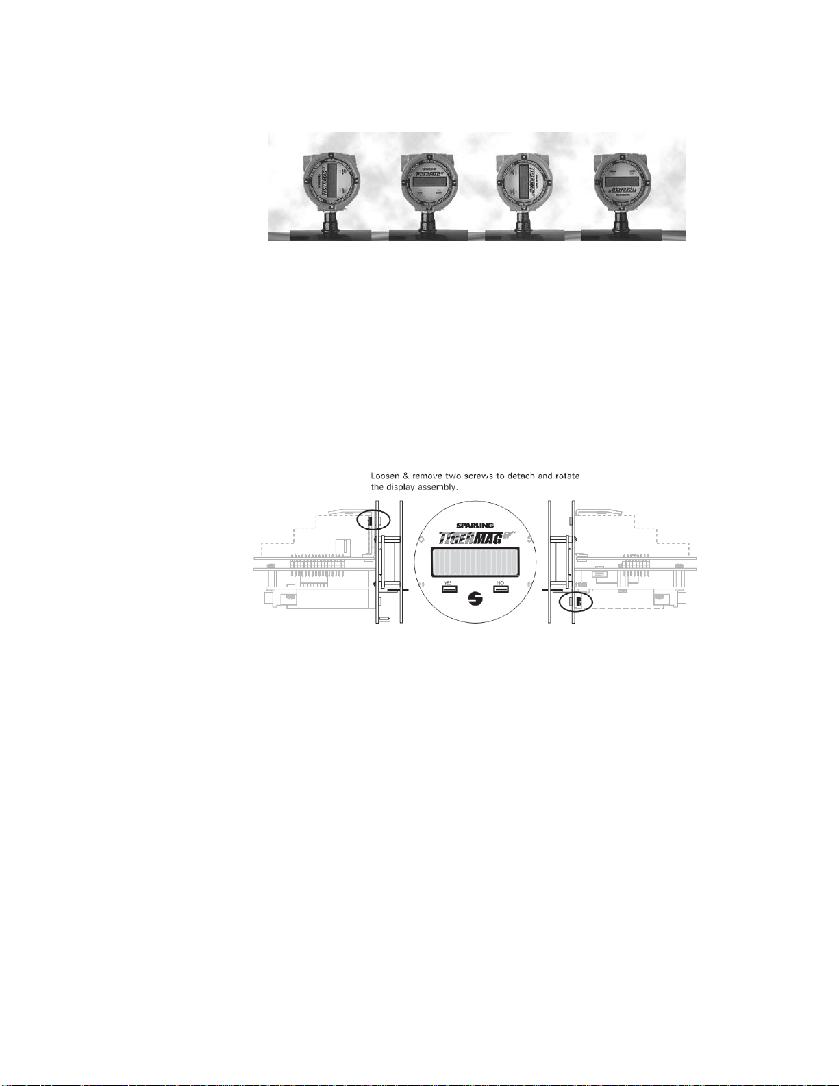
3.3
Rotating
the
T
r
ansmitter
Display
The Sparling TigermagEP's modular display
is
designed
to
allow
you to
rotate
the
display
in four
different orientations. The display assembly
can be
rotated,
at
90° intervals,
by
removing
the two
screws circled
in
Figure 3.2 below,
for
ease
of
reading
thedisplay.
The display features
long
lasting LCD numerals. The display may darken
if
ambient
temperatures
exceed its temperature rating
of
-4°
to+158°
F.Darkening usually occurs when the electronics
are
installed in direct sunlight. Toavoid this problem install
a
sun shield when the flowmeter
is
in
direct
sunlight.
The display assembly can be replaced in the field without replacing the entire electronics, by
following
the
same procedures
as
utilized
for
rotating
thedisplay.
Removing the Rotatable
Display
Figure 3.2
Page 12 TigermagEP™

3.4
Removable
Electrodes
(optional)
The line must be
depressurized
and drained in order to check and replace the removable
electrodes.
3.4.1 How the Design
W
orks
This design utilizes electrodes which are installed through accessible ports provided
on
the
sensor
body.
Electrodes are sealed using
two
o-rings. One o-ring
actsas a
primary seal while
the
other
is
a
backup seal. This redundant sealing approach provides positive
sealing.
To
withdraw
the
electrodes,
process line has to be
depressurized
and
drained. The
outercover
must be
removed
by
unscrewing
cap bolts using an
11/32
nut
driver
to
allow access
to the elec-
trode
cavity. Remove
cables from
electrodes
by
removing
nuts and lock
washers.
Usinga 3/4"
socket, unscrew
and
remove
the
electrode
assembly.
3.4.2 The Need for
Replacement
Sparling's flowmeter design utilizes High Impedance circuitry (Hi-Z) which
isnot
affected
bycoating
buildup
on the
electrodes. Replacement
of the
electrode
only
becomes necessary when
physical
damagedue to
erosion
or
corrosion
hasoccurred.
3.5
Hot
-
T
a
p
Removable
Electrodes
(optional)
Hot-Tap Removable
Electrode
Figure 3.4
Sparling's optional
hot-tap
removable electrode
design
allows
the
inspection
or
replacement
of
electrodes without
stopping the
flow
or
depressurizing
the
line. The electrode assembly
is sealed
with multipleo-rings to
maintain
isolation from the
pressurized
medium. During
removal
of the
electrode,
a
stainless steel
ball
valve
is closedto
keep
the
process fluid from leaking
out
while
the
electrodes are inspected
or
cleaned. The electrode housing, wired
as a backup
electrode,
func-
tions as a
redundant
electrodeassemblyproviding the flow signal to the
electronics.
In other
words,
even
when the
electrode
is
withdrawn,
the
flowmeter
keeps on providingimportantflow
information.
IDS-626/627/656/657
Page
13
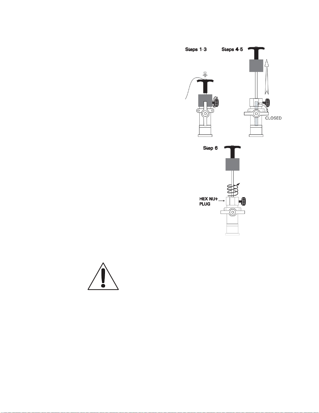
3.5
Hot-Tap
Removable
Electrodes
(cont'd)
3.5.1 Electrode Removal
1. Use a cross recessed (phillips) screwdriver
to remove the screw and lock washer from
the handle.
2. Gently remove the electrode cable (orange
wire) and place aside.
3. Secure cable then loosen the side knob.
4. Using the handle on the electrode head, pull
electrode straight to the point that the valve
can be closed.
5. Close the ball valve clockwise.
6. Unscrew the hex plug from the valve coun-
terclockwise and remove the electrode
assembly.
3.5.2 Electrode Installation
1. Install hex plug clockwise. Seal tight into closed
valve assembly.
2. Open ball valve counterclockwise.
3. Push electrode assembly in, aligning the slot
in the cover with the screw, until firmly seated.
4. Tighten the side knob.
5. Place electrode cables on handle.
6. Install the lock washer and screw, tighten.
7. Replace gasket, cover, cover screws and
tighten securely.
Removing the Electrode
Figure 3.5
CAUTION
3.5.3 When to Replace
Sparling's flowmeter design utilizes High Impedance circuitry (Hi-Z) which is not affected by coating
buildup on the electrodes. Replacement of the electrode only becomes necessary when physical
damage due to erosion or corrosion has occurred.
Page 14 TigermagEP™
●Avoid Scratching or damaging the withdrawn
electrodes
●Ball valve must be closed before the hex-head
electrode assembly is unscrewed and removed.
●Electrode hes-head assembly must be replaced
and secured tightly before opening the ball valve
and reinserting the electrode

LINER
MA
T
E
R
I
AL
GASKET
M
ATERIAL
Ceramic
Teflon
®
Tefzel
®
Teflon
®
Coated
Asbestos
Hard or
Soft
Rubber
Asbestos
Neoprene
Rubber
Neoprene
Asbestos
Neoprene
Rubber
Polyurethane
Asbestos
Neoprene
Rubber
F
M
627
Polyurethane
Armstrong
Syntheseal
3.6
Pipe
Connections
MODELS
FM626
&
FM627
FLANGELESS
(WAFER)
SENSOR
The
flangeless
sensor is installed between two process pipe flanges. The sensor contains a
nonconductive polyurethane, ceramic or Tefzel
®
liner. The integrity
of
this linermust
bemaintained
for
the flowmeter
to
function.
CARE SHOULD
BE
TAKEN DURING INSTALLATION
TO
INSURE
THAT THIS LINER
IS
NOT DAMAGED
. Depending upon meter size, four (4) or eight (8)
steel
bolts
are required for installation of the FM626 & FM627. These bolts are used to install the
meter
between
existing flanges. See Table
4.
Gaskets
are
required between
the
meter
and the
pipe
flanges
and
betweengrounding rings and the mating
surfaces.
Install the two bolts
at
the
bottomof
the meter. Place the meter temporarily between the flanges
to
confirm correct positioning. Themeter should rest directly
on the
bolts. Remove
themeter.
▼REINSTALL THE METER TAKING CARE TO KEEP THE GASKET
CENTERED.
INSTALL ALL BOLTS AND TURN FINGER TIGHT. COMPLETE
INSTALLATION WITH TORQUE WRENCH. IT IS IMPORTANT THAT THE BOLTS BE TIGHTENED
ALTERNATELY
SOTHAT
EXCESSIVE FORCE
IS NOT
APPLIED
TO A
CONCENTRATED
POINT. SEE
F
IGURE
3.6. DO
NOT
EXCEED
THE
TORQUE
LIMITS
IN
T
ABLE
6.
MODELS
FM656 & FM657
FLANGED
SENSORS
The flanged sensor is installed between two process pipe flanges. The sensing head tube interior
is
covered with an electrically nonconductive liner which overlaps the flange seal surfaces.
The
integrity
of this liner must be maintained for the flowmeter
to function
CARE SHOULD BE TAKEN
DURING
INSTALLATION TO INSURE THAT THIS LINER
IS
NOT DAMAGED. FLANGE
GASKETS
MUST BE USED.
Gasket material should be selected which is compatible with the piping and
proc
ess
conditions.
Table
4
contains typical satisfactory gasket materials. Do
not
use spiral
wound
metal
gaskets
as
they may cause liner
damage.
T
ab
l
e
4
-
G
as
k
e
t
M
at
e
r
i
al
▼
THE
GASKETS
, METER
FLANGES
, AND
MATING PIPE FLANGES SHOULD BE DUSTED
WITH GASKET TALC PRIOR TO INSTALLA-
TION TO PREVENT DAMAGE TO THE LINER
SHOULD IT BE
NECESSARY
TO
REMOVE
THE
METER FROM THE LINE. DO NOT USE
GRAPHI
TE
T
O DUST THE
GASKET. A
CONDUCTIVE
FILM
WI
LL COAT
T
HE
M
ETER
I
N
TERI
OR
A
ND CAUSE A
MALFUNCTION.
DO
NOT EXCEED THE TORQUE
LIMITS IN
T
ABLE
6.
IDS-626/627/656/657
Page
15

3.7
Special
Mounting
Bolts
&
Gaskets
Sparling provides
carbon steel
mounting hardware
with
wafer
meter
sizes 0.1"to
4",On flanged
meters,
special mounting bolts are providedfor meter sizes
0.5", 1.5"
and 3" only.
Gaskets
are
provided
for
ceramic sensors
only.
Optional 304SS mounting
bolts
for these sizes are available
at
extra
cost.
Tab
l
e
5
- Meter
I.D.
Nominal
I.D
.
Actual
I.D
.
Ceramic
O
th
e
r
i
n
in
mm
i
n
mm
0.10
0.25
0.50
1.0
1.5
2.0
2.5
3.0
4.0
6.0
8.0
10.0
12.0
14.0
16.0
18.0
20.0
24.0
30.0
36.0
42.0
48.0
54.0
60.0
66.0
72.0
0.125
0.302
0.452
0.812
1.34
1.69
N/A
N/A
N/A
N/A
N/A
N/A
N/A
N/A
N/A
N/A
N/A
N/A
N/A
N/A
N/A
N/A
N/A
N/A
N/A
N/A
3.17
7.67
11.48
20.62
34.04
42.93
N/A
N/A
N/A
N/A
N/A
N/A
N/A
N/A
N/A
N/A
N/A
N/A
N/A
N/A
N/A
N/A
N/A
N/A
N/A
N/A
N
/
A
N
/
A
0.48
0.91
1.47
1.94
2.24
2.87
3.83
6.00
7.75
10.00
12.00
13.00
15.00
17.00
19.00
22.90
29.00
34.60
40.60
46.60
52.50
58.50
64.50
70.25
N
/
A
N
/
A
12.24
23.09
37.34
49.20
56.90
72.85
97.18
152.40
196.85
254.00
304.80
330.20
381.00
431.80
482.60
581.66
736.60
878.84
1031.24
1183.64
1333.50
1485.90
1638.30
1790.70
Page 16 TigermagEP™
This manual suits for next models
4
Table of contents
Other SPARLING Measuring Instrument manuals


Popular Measuring Instrument manuals by other brands


Bender
Bender LINETRAXX RCM420 installation manual

NUCLEONIX SYSTEMS PRIVATE LIMITED
NUCLEONIX SYSTEMS PRIVATE LIMITED GR612 instruction manual

Bruker BioSpin
Bruker BioSpin minispec mq60 user manual

Eyedro
Eyedro EYEDRO-HOME Product guide

Newtons4th
Newtons4th SFRA45 Quick Measurement Guide

Vaisala
Vaisala GMP252 user guide


