Energetics ET 620 User manual

ET 620 Crosstrainer
Assembly manual
EN
Aufbauanleitung
DE
Montažni přiručka
CS
Manual na montaž
SK
Felhasznaloi kezikonyv
HU
60 -80 Min
120 kg
A: 160 cm
B: 145 cm
C: 52 cm
47 kg

2
Table of contents - Inhaltsverzeichnis -Obsah - Obsah - Tájékoztató
English
P
3
Deutsch
P
22
Česky
P
41
Slovensky
P
60
Magyar
P
79
Serial Decal / Seriennummeraufkleber / Štitek se seriovym čislem / Seriovy štitok / Cimke
EN
The product sticker is placed on the rear stabilizer on
bikes and ellipticals and next to the power inlet on
treadmills
DE
Der Aufkleber für die Seriennummer ist bei
Heimtrainern oder Ellipticals auf der hinteren Quer-
stütze angebracht, bei Laufbändern in der Nähe des
Stromanschlusses.
CZ
Štitek vyrobku se nachazi na zadnim tabilizatoru kol a
eliptickych trenažerůa vedle elektrickeho přivodu na b
ěžeckych trenažerech.
SK
Štitok vyrobku je umiestneny na zadnej strane
stabilizatora na bicykloch a kolesach a blizko pri
napajani na bežeckom pase.
HU
A termek ontapados cimkeje a kerekparok es
szobakerekparok hatso stabilizatoran van elhelyezve es
a pedalokon a tapbemenet mellett.
EN
© The owners manual is only for the customer reference. ENERGETICS can not guarantee for mistakes occurring due to translation
or change in technical specification of the product. Wherever pictograms are used they may differ from your product, it’s for
reference only.
DE
© Die Gebrauchsanweisung dient nur zur Referenz für den Kunden. ENERGETICS übernimmt keine Haftung für Fehler, die durch
Übersetzung oder technische Änderungen des Produkts entstehen. Falls Piktogramme verwendet werden, können diese von Ihrem
Produkt abweichen und dienen nur als Referenz.
CZ
© Navod k použiti je pouze doporučeni pro zakazniky. ENERGETICS nepřebira žadne ručeni za chyby způsobene překladem či změ
nami v technicke specifikaci vyrobku. Použiti piktogramův tomto navodu se může lišit od skutečneho použiti na vašem vyrobku,
rozmistěni v tomto navodu slouži pouze pro informaci.
SK
© Tento návod je určený len pre potrebu zákazníkov. ENERGETICS nezodpovedá za chyby, ktoré sa môžu vyskytnúť kvôli chybnému
prekladu alebo zmenám v technickej špecifikácii produktu. Všade, kde sa používajú piktogramy, sa tieto môžu líšiť od vášho produktu
a sú určené len na referenčné účely.
HU
© A vásárlók számára a jelen használati utasításnak csak ajánló jellege van. Az ENERGETICS cég nem vállal kezességet olyan jellegű
hibákért, amelyek az eredeti szöveg fordításából, illetve a termék módosított műszaki specifikációjából származnak. A használt
piktogramok eltérhetnek a termék piktogramjaitól. Ezek csak
tájékoztató jellegűek.

3
Corporate Social Responsibility
EN
INTERSPORT is a participating company in the BSCI (Business Social Compliance Initiative) based in
Brussels. Through BSCI, INTERSPORT is committed to implement the BSCI Code of Conduct in its supply
chain and to gradually achieve better working conditions at the involved suppliers’ workplaces. The BSCI
system is based on three pillars: monitoring of non-compliances by external independent audits;
empowering of supply chains’ actors through various capacitybuilding activities; and engagement with
all relevant stakeholders via constructive dialogue in Europe and supplying countries. Our social audits
are conducted by neutral, internationally recognized auditing companies with the aim of monitoring the
social compliance of our supplier factories.
For more information on the BSCI please visit: www.bsci-intl.org
Norms & Regulations
Consumer safety is the number one priority for ENERGETICS products. This means that all of our products
comply with national and international legal requirements (such as the EU Regulation (EC No.
1907/2006) concerning the Registration, Evaluation, Authorization and Restriction of Chemicals
[REACH]).
This product is also CE certified and has been tested by an internationally
recognized institute and certified against the industry standard EN 957.
Disposal of electrical waste products (Directive 2002/96/EC WEEE):
All products that contain electrical and electronic equipment must be marked
with the logo. These products shall not be disposed in municipal waste. Instead
please check local regulations regarding these types of products.
Disposal of batteries (Directive 2006/66/EG):
Batteries must be marked with the logo including the chemical symbols Hg, Cd
or Pb if the battery contains mercury, cadmium or lead above the threshold limits
mentioned in the directive and its amendments. Batteries used in products shall
not be disposed in municipal waste.
Directive 2011/65/EU:
Restriction of the use of certain hazardous substances in electrical and electronic
equipment (RoHS).

4
Dear Customer,
Congratulations on your purchase of an ENERGETICS home fitness equipment. This product
has been designed and manufactured to meet the needs and requirements of in-home use.
Please carefully read the assembly- and user manual. Be sure to keep the instructions for
reference and/or maintenance. If you have any further questions, please contact us. We wish
you lots of success and fun while training.
Your ENERGETICS - Team
Product Safety
ENERGETICS offers high quality home fitness equipment. All products have been tested and
certified according to the latest European Norm ISO EN 20957-1, EN 957-5.
Important Safety Instructions for all home fitness equipment
Do not assemble or operate this home fitness equipment outdoors or in a wet or moist
location.
Before you start training on your home fitness equipment product, please read the
instructions carefully.
Be sure to keep the instructions for information, in case of repair and for spare part
delivery.
This training equipment is not suitable for therapeutic purposes.
Consult your physician before starting with any exercise programs to receive advice on
the optimal training.
Warning: incorrect/excessive training can cause health injuries. Stop using the home
fitness equipment when feeling uncomfortable.
Warning: The safety level of the training equipment can only be maintained if it is
examined regularly on damage or wear.
Please follow the advice for correct training as detailed in the training instructions.
Ensure that training only starts after correct assembly, adjustment and inspection of the
home fitness equipment.
Always start with a warm-up session.
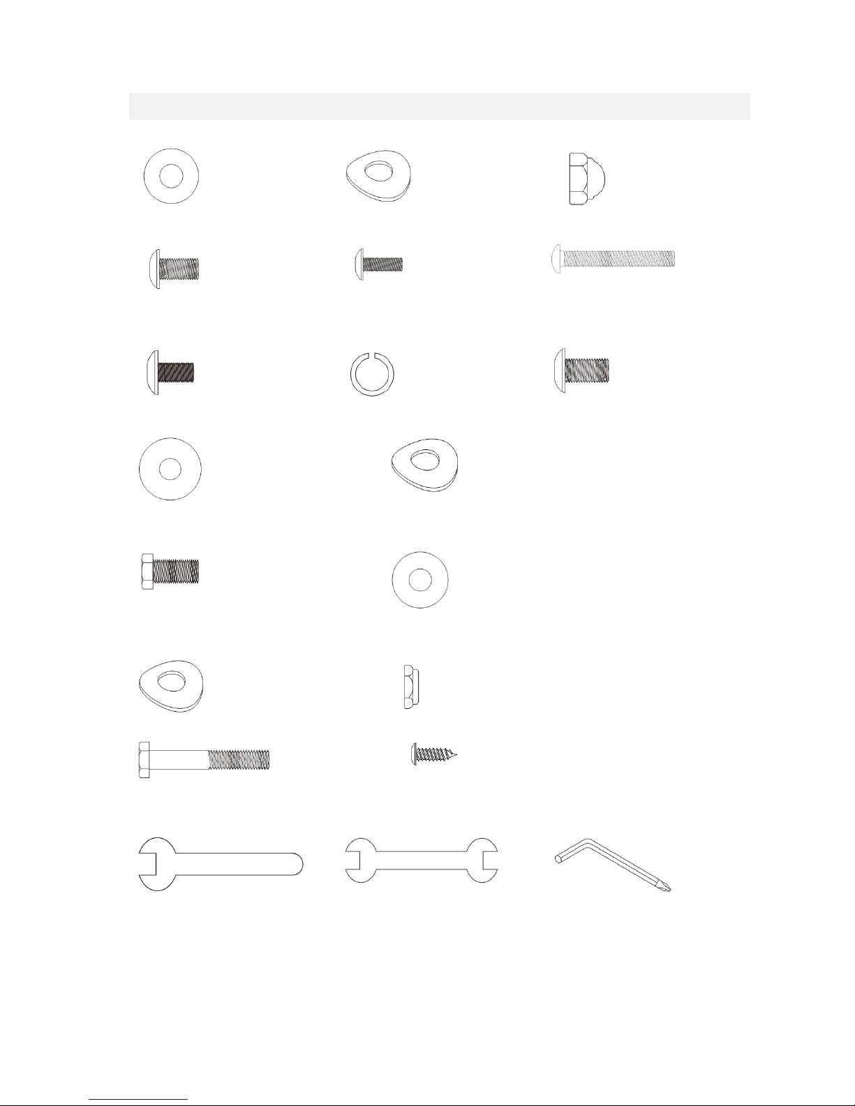
Only use original ENERGETICS parts as delivered (see partslist).
Follow the steps of the assembly instruction carefully.
Only use suitable tools for assembly and ask for assistance if necessary.
Place the home fitness equipment on an even, non-slippery surface for immobilization,
reducing noise and vibration.
To protect the floor or carpet from damage, place a mat under the product.
For all adjustable parts be aware of the maximum position to which they can be adjusted.
Tighten all adjustable parts to prevent sudden movement while training.
This product is designed for adults. Please ensure that children only use it under the
supervision of an adult.
Do not use the home fitness equipment without shoes or loose shoes.
Be aware of non-fixed or moving parts whilst mounting or dismounting the home fitness
equipment.
Search for noisy parts: If you should notice unusual noises, like grinding, clacking etc. try
to locate it and have it repaired by a professional. Make sure the home fitness equipment
is not used until after repairs have been made.

5
This device is not meant to be used by persons (including children) with limited physical,
sensory or mental capabilities or lacking experience and/or the knowledge to use this
device, unless under the supervision of another person in charge of their safety or having
been given prior instruction on the operation of this device.
Children should always be under supervision, to assure they are not playing with this
device.
The resistance level can be adjusted to your personal preference: see operations.
This product is made for home use only and tested up to a maximum body weight of: see
front page or serial decal on product.
WARNING: Heart rate monitoring systems may be inaccurate. Over exercising may result
in serious injury or death. If you feel faint stop exercising immediately.
Cleaning, Care & Maintenance on fitness equipment
Important
Frequent cleaning of your home fitness equipment will extend the product’s life.
Use of a home fitness equipment mat is recommended for ease of cleaning.
Use clean and proper sport shoes only.
Use a damp cloth to clean the home fitness equipment and avoid the use of
abrasives or solvents.
To prevent damage to the computer, keep liquids away and keep it out of direct
sunlight.
The home fitness equipment should not be used or stored in a moist area because
of possible corrosion.
In case of repair please ask your dealer for advice.
Replace defective components immediately and/or keep the equipment out of use
until repair.
Use original spare parts for repair only.
Daily
Monthly
Immediately wipe of the sweat;
perspiration can ruin the appearance
and proper function of the home
fitness equipment.
Check that all connecting elements
are tightly fitted and in good
condition.

6
Handling
Leveling
Transportation
After assembly, the rear stabilizer can be
adjusted to accommodate slightly uneven
ground. Turn the adjustment knobs at the ends
of the rear foot caps to level the rear stabilizer
to the floor.
The transportation wheels on the front foot caps
allow for easy manoeuvring. Simply pull back on
the handlebars until the wheels touch the floor.
Then roll the unit to a desired location.
Pedal Adjustment (where applicable)
A correct pedal adjustment will ensure you can do your exercise more efficiently and comfortable. It also
will reduce the risk of any injury while using.
1. Loosen the two screws underneath the pedal.
2. Slide the pedal back or forth until you found the
correct position.
3. Re-enter the two screws and tighten the nuts
securely.
4. You can start your exercise.
Make sure all screws are tightened well after you have made your adjustments.
Operations
Proper Training Clothes
Please make sure you always wear proper training shoes while working out. It is recommended that you
wear training appropriate exercise clothing’s that allow you to move freely whilst exercising.
Exercise Level
Please contact a physician before your exercise program. Immediately stop exercising if you feel any pain
or tightness in your chest, become short breathed of faint. Please contact your doctor before you start
using your fitness product again.
Resistance Adjustment
Manual adjustment
The resistance can be changed by turning the
resistance knob. To increase the resistance
turn the knob clockwise, to decrease it counter
clockwise.
Computer controlled adjustment
The resistance can be Increased or decreased on the console (if applicable). Please consult the computer
manual for further information.

7
Exploded drawing

8
Part list
Part
Description
Qty
Part
Description
Qty
1
Main Frame
1
48
Adjustment Foot Pad
2
3
Crank Arm Assembly
2
49
WFM-1719-12_Bushing
4
5
Pedal Arm (L)
1
50
J4FM-1719-09_Bushing
4
7
Connecting Arm (L)
1
51
Drive Pulley
1
8
Connecting Arm (R)
1
52
Ø32(1.8T)_Button Head Plug
2
9
Lower Handle Bar (L)
1
53
Podwer metallurgy Bushing
4
10
Lower Handle Bar (R)
1
54
Rubber Foot
2
11
Console Mast
1
55
Round Cap
2
12
Idler Wheel Assembly
1
56
Pedal Axle Spacer
2
13
Crank Axle
1
57
Spacer Bushing
1
14
Front Stabilizer
1
58
Side Case(L)
1
15
Swing Arm (L)
1
59
Side Case(R)
1
16
Swing Arm (R)
1
60
Crank Arm End Cap
2
18
Rod End Shaft(Blackfast)
2
61
Ø56 × Ø19 × 15L_Bushing
2
19
Axle for Slide Wheel(Blackfast)
2
62
Ø56 × Ø19 × 21L_Bushing
2
22
Aluminum Track
2
63
Pedal (L)
1
23
6005_Bearing
2
64
Pedal (R)
1
24
6003_Bearing
4
65
Slide Wheel Cover
2
25
Axle for Idler Wheel
1
66
Ø42 × Ø19 × 15L_Bushing
4
27
Belt
1
67
Pedal Bushing
4
28
Flywheel
1
68
Bolt Access Cap
1
29
Magnet
1
69
Front Handle Bar Cover (L)
1
30
Handgrip Foam
2
69~1
Rear Handle Bar Cover (L)
1
31
Steel Cable
1
70
Front Handle Bar Cover (R)
1
35
Console Assembly
1
70~1
Rear Handle Bar Cover (R)
1
36
1600m/m_Computer Cable
1
73
1/4" × UNC20 × 3/4"_Hex Head
Bolt
4
37
450m/m_DC Power Cord
1
74
5/16" × UNC18 × 15L_Hex Head
Bolt
8
38
Gear Motor
1
75
5/16" × UNC18 × 15L_Hex Head
Bolt
2
39
200m/m_Sensor W/Cable
1
76
5/16" × UNC18 × 1-3/4"_Hex
Head Bolt
6
40
800m/m_Handpulse W/Cable
Assembly
2
77
3/8" × UNC16 × 3"_Carriage Bolt
2
41
Power Adaptor
1
78
3/8" × UNC16 × 27L_Carriage Bolt
1
42
Console Mast Cover (L)
1
79
M8 × P1.25 × 25L_Socket Head
Cap Bolt
2
43
Console Mast Cover (R)
1
80
5/16" × UNC18 × 15L_Button
Head Socket Bolt
6
44
Transportation Wheel
2
80~1
5/16" × UNC18 × 15L_Button
Head Socket Bolt
2
46
Round End Cap
2
82
M5 × P0.8 × 15L_Phillips Head
Screw
4
47
Slide Wheel , Urethane
2
83
M5 × P0.8 × 10L_Phillips Head
Screw
10

9
84
M5 × P0.8 × 10L_Phillips Head
Screw
4
105~1
5/16" × 23 × 3T_Flat Washer
4
85
Ø5 × 19L_Tapping Screw
9
107
Sleeve
1
85~1
Ø5 × 19L_Tapping Screw
4
108
M8 × P1.25 × 130L_J Bolt
1
86
Ø3.5 × 16L_Sheet Metal Screw
9
109
M8 × P1.25 × 20L_Carriage Bolt
1
87
Ø3.5 × 12L_Sheet Metal Screw
8
111
Ø8 × 1.5T_Split Washer
6
88
Ø3 × 20L_Tapping Screw
4
112
Ø10 × 23 × 1.5T_Curved Washer
2
89
Ø25_C Ring
1
113
Ø8 × 23 × 1.5T_Curved Washer
6
90
3/8" × UNC16 × 7T_Nyloc Nut
1
114
Woodruff Key
2
91
5/16" × UNC18 × 7T_Nyloc Nut
6
115
13/14m/m_Wrench
1
92
M8 × P1.25 × 7T_Nyloc Nut
1
116
12m/m_Wrench
1
93
M8 × P1.25 × 9T_Nyloc Nut
1
118
Combination M5 Allen Wrench &
Phillips Head Screw Driver
1
94
1/4" × UNC20 × 8T_ Nyloc Nut
4
119
Ø8 × 16 × 1T_Flat Washer
1
96
3/8" × UNC16 × 12.5T_Cap Nut
2
120
Ø5 × 16 × 1.5T_Flat Washer
1
97
3/8" -UNF26 × 4T_Nut
2
134
M6 × P1.0 × 15L_Phillips Head
Screw
4
98
3/8"-UNF26 × 11T_Nut
2
135
Oval End Cap
2
99
3/8" × UNC16 × 7T_Nut
2
136
Round Cap
8
102
Ø8.7 × Ø20 × 1.5T_Flat Washer
2
137
C Ring
2
103
Ø8 × Ø35 × 1.5T_Flat Washer
2
138
Sleeve
2
104
Ø8.5 × 26 × 2.0T_Flat Washer
2
139
Pedal Arm(R)
1
104~1
Ø8.7 × Ø20 × 1.5T_Flat Washer
2
142
5/16" × 15L_Hex Head Bolt
4
105
Ø8 × 23 × 1.5T_Flat Washer
11
143
Handgrip End Cap
2

10
Checklist
Step 1
#104-1 Ø 8.7 × 20 × 1.5T Flat Washer
(2pcs)
#112. 3/8" × 23 × 1.5T Curved Washer
(2pcs)
#96. 3/8" Cap Nut (2pcs)
#80-1 5/16" × 15m/m Button Head
Socket Bolt (2pcs)
#82. M5 × 15m/m Phillips Head Screw
(4pcs)
#77. 3/8" × 3" Carriage Bolt (2pcs)
Step 2
#84. M5 × 10m/m Phillips Head Screw
(4pcs)
#111. 5/16" × 1.5T Split Washer (6pcs)
#80. 5/16" × 15m/m Button Head
Socket Bolt (6pcs)
#105. 5/16" × 23 × 1.5T Flat Washer (4pcs)
#113. 5/16" × 23 × 1.5T Curved Washer (2pcs)
Step 3
#74. 5/16" × 15m/m Hex Head Bolt (2pcs)
#102. Ø 8.7× 20 × 1.5T Flat Washer (2pcs)
Step 4
#113. 5/16" × 23 × 1.5T Curved Washer (4pcs)
#91. 5/16" × 7T Nyloc Nut (6pcs)
#76. 5/16" × 1-3/4" Hex Head Bolt (6pcs)
#87. Ø3.5 × 12m/m Sheet Metal Screw (8pcs)
Tools
#116. 12 mm Wrench (1pcs)
#115. 13 &14 mm Wrench (1pcs)
#118. Combination 5mm Allen Wrench
& Phillips Head Screw Driver (1pcs)

11
Assembly instruction
Step 1 Front Stabilizer and Connecting
Arm Assembly
1. Install the Front Stabilizer (14) on the front stabilizer holding plate at the bottom of the main frame
with the transportation wheels facing forward and secure them with 2pcs of 3/8" × 3" Carriage Bolts
(77), 2pcs of 3/8" × 23m/m × 1.5T Curved Washers (112) and 2pcs of 3/8" Cap Nuts (96) by using
13.14m/m Wrench (115).
2. Secure 2pcs slide wheel cover (65) on left and right pedal arm (5) with four M5 × 15m/m Phillips
Head Screws (82) by using Combination M5 Allen Wrench & Phillips Head Screw Driver (118).
3. Insert the shaft on left connecting arm (7) to the bushing on left pedal arm (5) and secure with 1pcs
5/16" × 15m/m Button Head Socket Bolt (80-1) together with 1pcs Ø8.7 × 20 ×1.5T Flat Washer (104-
1) by using Combination M5 Allen Wrench & Phillips Head Screw Driver (118). Do it the same way
for right connecting arm (8) and right pedal arm (5).

12
Step 2 Console Mast Assembly
1. Use cable tie to guide the 1150m/m Computer Cable(36) through Console Mast(11) and then pull
out of the console holding plate, and Insert the console mast into main frame and secure with 6pcs
of 5/16" × 15m/m Button Head Socket Bolts (80), 6pcs of 5/16" × 1.5T Split Washers (111), 4pcs of
5/16" × 23m/m × 1.5T Flat Washers (105) and 2pcs of 5/16" × 23m/m × 1.5T Curved Washers (113)
by using Combination M5 Allen Wrench & Phillips Head Screw Driver (118) .
2. Take off the cable tie which ties the Computer Cable (36) and plug in the connectors of the Computer
cable and the two Handpulse W/Cable Assemblies (40) on the Console. Secure the Console on the
Console Assembly (35) with 4pcs of M5 × 10m/m Phillips Head Screws (84) by using Combination M5
Allen Wrench & Phillips Head Screw Driver (118). Pay attention to Avoiding scratching the cables.

13
Step 3 Handle Bar Assembly
1. Install the Lower Handle Bar (L) (9) in the left shaft of Console Mast (11) and the Lower Handle Bar
(R) (10) in the right shaft of Console Mast (11), and secure them with 2pcs of 5/16" × 15m/m Hex
Head Bolts (74) and 2pcs of Ø8.7 × 20m/m × 1.5T Flat Washers (102) by using 12m/m Wrench (116).
2. Release rod end shafts (18) which are on left and right connecting arms. Connect the connecting arm
with lower handle bar and secure with rod end shafts (18) and the screw by using 12m/m_Wrench
(116).

14
Step 4 Connecting Arm Assembly
1. Connect the Swing Arm (L) (15) to the left Lower Handle Bar and connect the Swing Arm (R) (16) to
the right Lower Handle Bar, and secure them with 6pcs of 5/16" ×1-3/4" Hex Head Bolts (76),4pcs of
5/16" × 23m/m × 1.5T Curved Washers(113) and 6pcs of 5/16" × 7T Nyloc Nuts (91) by using 12m/m
Wrench(116) 13.14m/m Wrench (115).
2. Put the Front Handle Bar Cover (L) (69) and the Rear Handle Bar Cover (L) (69~1) together on the left
Handle Bar and secure with 3pcs of Ø3.5 × 12m/m Sheet Metal Screws (87) by using Combination
M5 Allen Wrench & Phillips Head Screw Driver(118). Repeat the same procedure for the right side.
3. Connect the Console Mast Cover (L)(42) and the Console Mast Cover (R)(43) together on the Console
Mast and secure with 2pcs of Ø3.5 × 12L_Sheet Metal Screw (87) by using Combination M5 Allen
Wrench & Phillips Head Screw Driver(118).

15
Computer manual
KEY FUNCTIONS
START/STOP
1. Start & Pauses workouts.
2. Start body fat measurement.
3. Holding key for 3 seconds will reset all function value to be zero.
DOWN
Decrease value of selected workout parameter: TIME, DISTANCE, etc.
During the workout, it will decrease the resistance load.
UP
Increases value of selected workout parameter. During the workout, it will
increase the resistance load.
ENTER
To input desired value or work out mode.
RECOVERY
Press to enter into Recovery function when computer has the heart rate value.
Recovery is Fitness Level 1-6 after 1 minute.F1 is the best, and F6 is the worst.
MODE
Press to switch display form RPM to SPEED, ODO to DIST during workout.
Workout Selection
After power-up using UP or DOWN keys to select then pressing ENTER to enter the desired mode.
There are 6basic workout modes:
Manual, Pre- programs, Body Fat Program, Target Heart Rate program, Heart Rate Control program
and User Program.

16
FUNCTIONS
SPEED
Display current training speed. Maximum speed is 99.9 KM/H or MILE/H.
RPM
Display current rotation per minute.
TIME
Accumulate the workout time from 00:00 to 99:59. Or users can preset the
target time they want.
DISTANCE
Accumulate the workout distance form 0.00 up to 999.9 KM or Mile. Or users
can preset the target distance they wan to reach.
ODO
Display the total accumulated distance from 0.0 to 999.9KM or Mile
CALORIE
Accumulate the calories consumption from 0 to 9999. Or users can preset the
target Calories they want to consume.
HEART RATE
Display the current heart rate in beats per minute.
TARGET H.R.
Users can preset their Target Heart Rate.
PROGRAM
There are 24 different programs to choose for training.
LEVEL
The program has 24 levels loading and 8 bars in each column. Each column
represents 1 minute workout (without the change of time value) and each bar
represents 3 levels loading.
MUSIC
There is an audio-input port on the top of the monitor, user can connect the
MP3 to the Audio-input, and turn on the MP3, it will be playing music.
Workout Parameters
TIME / DISTANCE / CALORIES / AGE / TARGET HEART RATE
Setting Workout Parameters
After selecting desired workout mode: Manual, Pre-set Programs, Body Fat, Target Heart Rate, Heart
Rate Control and User Program. You may pre-set several workout parameters for desired results.
Note: Some parameters are not adjustable in certain programs. Time and Distance can not be set up at
the same time.
Once a program has been selected, pressing ENTER, will make “Time” parameter flash. Using UP OR
DOWN KEY you may select desired time value. Press ENTER KEY to input value.
Flashing prompt will move to the next parameter. Continue use of UP OR DOWN KEY. Press START/STOP
to start workout.

17
More About Workout Parameters
Field
Setting Range
Default Value
Increment/
Decrement
Description
Time
0:00~ 99:00
00:00
± 1:00
1. When display is 0:00, Time will
count up.
2. When time is 1:00-99:00, It will
count down to 0.
Distance
0.00~999.0
0.00
±1.0
1. When display is 0.0, Distance will
count up.
2. When Distance is 1.0~999.0, it will
count down to 0.
Calories
0~9995
0
±5
1. When display is 0, Calories will
count up.
2. When Calories is 5~9995, it will
count down to 0.
Age
10~99
30
±1
Target HR will be based on Age. When
Heart Rate exceeds Target H.R, the
number of Heart Rate will flash
Pulse
60~220
90
±1
Setting Parameters for Target heart
rate
Program Operation
Manual(P1)
Selecting “Manual” using UP OR DOWN KEY then pressing ENTER KEY.
1St parameter “Time” will flash so value can be adjusted using UP OR DOWN KEY. Press ENTER KEY to
save value & move to next parameter to be adjusted.
**(If user sets up the target time to workout, then the next parameter of Distance can not be adjusted)
Continue through all desired parameters, pressing START/STOP to start workout.
Note: One of workout parameters counts down to be zero, it will have bi sounds and stop the workout
automatically. Press START KEY to continue the workout to reach the unfinished workout parameter.

18
Pre-programs (P2~P13)
Program profile
ROLLING
VALLEY
FAT BURN
RAMP
STEPS
OBSTACLE
INTERVALS
PLATEAU
CLIMBING
OFF ROAD
HILL
FARTLEK
There are 12 program profiles ready for use:ROLLING, VALLEY, FAT BURN, RAMP, STEPS, OBSTACLE,
INTERVALS, PLATEAU, CLIMBING, OFF ROAD, HILL and FARTLEK. All program profiles have 24 levels of
resistance.

19
Setting Parameters for Pre-programs
Selecting one of pre-programs using UP OR DOWN KEY then pressing ENTER KEY.
1St parameter “Time” will flash so value can be adjusted using UP OR DOWN KEY .Press ENTER KEY to
save value & move to next parameter to be adjusted. Continue through all desired parameters, pressing
START/STOP to start workout.
Workout in any pre-program
Users can exercise with different level of loading in different intervals as the profiles flash. Users may
exercise in any desirous of resistance level adjusting by UP/DOWN keys during the workout.
Note: If user sets up the target time to workout, then the next parameter of Distance can not be
adjusted. One of workout parameters counts down to be zero, it will have bi sounds and stop the
workout automatically. Press START KEY to continue the other unfinished parameter will continue
counting down.
BODY FAT PROGRAM
Program profile
Setting Data for Body Fat
Selecting “BODY FAT Program” using UP OR DOWN KEY then pressing ENTER.
“Male” will flash so Gender can be adjusted using UP OR DOWN KEY, press ENTER to save gender & move
to next data.
“175” of Height will flash so Height can be adjusted to use UP OR DOWN KEY, press ENTER KEY save value
& move to next data.
“ 75 “of Weight will flash so Weight can be adjusted to use UP OR DOWN KEY, press ENTER KEY to save
vale & move to next data.
“30” of Age will flash so Age can be adjusted using UP OR DOWN KEY, press ENTER to save value.
Press START/STOP to start measurement, please also grasp hand pulse grips.
After 15 seconds the display will show out Body Fat %, BMR, BMI & BODY TYPE.
Note: Body Types:
There are 9 body types divided according to the FAT% calculated. Type 1 is from 5% to 9%. Type 2 is
from 10% to 14%. Type 3 is from 15% to 19%. Type 4 is from 20% to 24%. Type 5 is from 25% to 29%.
Type 6 is from 30% to 34%. Type 7 is from 35% to 39%. Type 8 is from 40% to 44%. Type 9 is from 45%
to 50%.
BMR: Basal Metabolism Ratio
BMI: Body Mass Index
Press START/STOP KEY to return the main Display.

20
TARGET HEART RATE Program
Program profile
Setting Parameters for TARGET H.R
Selecting “TARGET H.R.” using UP OR DOWN KEY then pressing ENTER KEY.
1St parameter “Time” will flash so value can be adjusted using UP OR DOWN KEY. Press ENTER KEY to
save value & move to next parameter to be adjusted.
**(If user sets up the target time to workout, then the next parameter of Distance can not be adjusted)
Continue through all desired parameters, pressing START/STOP to start workout.
Note: If Pulse is above or below (± 5) the setting TARGET H.R, the computer will adjust the resistance
load automatically. It will check Every 10 seconds approx. l level load will increase or decrease (Note:
each resistance load represents 3 levels of loading).when the heart rate signal disappeared, the
computer will keep the resistance load constant for 60s, then it will decrease the resistance load 1 level
per 10s.
One of workout parameters counts down to be zero, it will have bi sounds and stop the workout
automatically. Press START/STOP to continue the workout to reach unfinished workout parameter.
HEART RATE CONTROL Program
Program profile
There are 4 selection for target pulse:
HRC - 55% TARGET H.R= 55% of (220-AGE)
HRC - 65% TARGET H.R= 65% of (220-AGE)
HRC - 75% TARGET H.R= 75% of (220-AGE)
HRC - 85% TARGET H.R= 85% of (220-AGE)
Setting Parameters for HEART RATE CONTROL
Selecting “One of Heart Rate Control Program .” using UP OR DOWN KEY then pressing ENTER KEY. 1St
parameter “Time” will flash so value can be adjusted using UP OR DOWN KEY .Press ENTER KEY to save
value & move to next parameter to be adjusted.
**(If user sets up the target time to workout, then the next parameter of Distance can not be adjusted)
Continue through all desired parameters, pressing START/STOP to start workout.
Note: If Pulse is above or below (± 5) the setting TARGET H.R. the computer will adjust the resistance
load automatically. It will check Every 10 seconds approx. l level load will increase or decrease (Note:
each resistance load represents 3 levels of loading).when the heart rate signal disappeared, the
computer will keep the resistance load constant for 60s, then it will decrease the resistance load 1 level
per 10s.
One of workout parameters counts down to be zero, it will have bi sounds and stop the workout
automatically. Press START/STOP KEY to continue the workout to reach unfinished workout parameter.
Table of contents
Languages:
Other Energetics Elliptical Trainer manuals

Energetics
Energetics ET 210 User manual

Energetics
Energetics XT 910 User manual

Energetics
Energetics XT 740T User manual

Energetics
Energetics ET 610 User manual

Energetics
Energetics XT 1010 User manual

Energetics
Energetics XT 740T User manual

Energetics
Energetics XT 1090 Series User manual

Energetics
Energetics ET 870 PRO User manual

Energetics
Energetics XT 420p User manual

Energetics
Energetics ET 1070 User manual