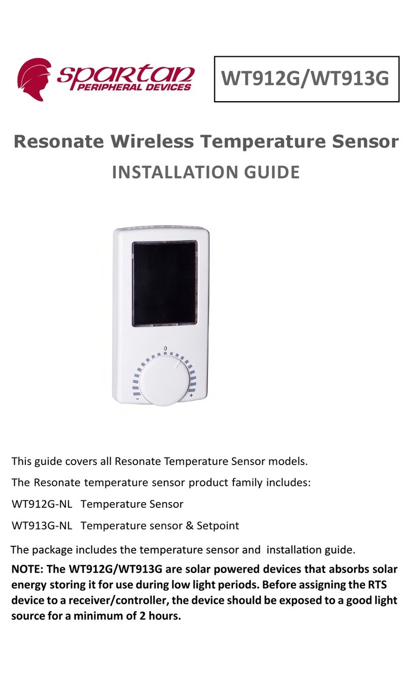
Spartan WT913G User manual

WT913G
Resonate Wireless Temperature Sensor
This guide covers all Resonate Temperature Sensor models.
The Resonate temperature sensor product family includes:
WT913G-NL Temperature Sensor & Setpoint
NOTE: The WT913G is a solar powered device that absorbs solar energy storing
it for use during low light periods. Before assigning the RTS device to a receiver/
controller, the device should be exposed to a good light source for a minimum
of 2 hours.
INSTALLATION GUIDE

2
The temperature sensor
(also referred to as the sensor in this guide)
of 0-100% . The sensor is intended for indoor use only.
Some models have a temperature set point knob and/or a fan speed
adjust how the temperature control operates.
-
voke an occupancy event (for RTS-2HS models) or to go into test mode
ayllacipytsihcihwrevieceraotstimsnartrosneserutarepmetehT
device that is programmed to provide temperature control in the space
that the sensor is monitoring for closed loop temperature control. The
sensor and receiver must be within range, preferably in the same room
-
ing 50’ (15.2 m) range, greater care must be taken to insure proper re-
Even with a brief exposure to light the sensor will operate; however for
ehtniatnoctahtsmargeletsutatsstimsnartrosneserutarepmetehT
•A5-10-03: Temperature Sensor + Temperature Set Point Control
The valid ranges for each data element:
•Temperature: 0 - 40°C, (32° - 104°F)
•
•Humidity Sensor: 0 -100% RH
•Fan Speed Switch: Auto, OFF, Low (1) Med (2), High (3)
•

3
Temperature Sensing Operaon
Temperature and Humidity Monitoring - The temperature sensor will
record the temperature, temperature set point and humidity values*
every 10 seconds (sample period) when there is approximately 100 lux
(10 foot-candles) available. If there is less than 100 lux (10 fc), the sam-
ple period will increase to 100 seconds. Aer 24 hours at < 15 lux (1.5
fc) the sample period will increase to 200 seconds. *Assuming sucient
storage charge to operate.
Temperature Set Point - Users can adjust the temperature set point by
rotang the knob counterclockwise to lower the set point value; clock-
wise to increase the set point value.
The receiving temperature control equipment must scale the set point
range to values that are applicable for the applicaon.
Fan Speed Switch - Users can adjust the fan speed switch by sliding the
switch to a seng: Auto, OFF, Low (1) Med (2), High (3).
Occupancy Buon - (RTS-2HS models only) Users can override a room
occupancy state by pressing the occupancy buon on the lower right
edge of the sensor.
LED Operaon - LEDs are on the right side of the solar panel. The red
LED will ash when the Link or Occupancy buon is pressed. See Test
Operang Modes for further LED informaon.
Transming Values - The temperature sensor will transmit a telegram
when:
• 10 sample periods have been completed or
• when the fan switch or occupancy buon are used or
• when the temperature value dierence from the last transmied
value is greater than 0.3°C, (0.5°F) or
• the humidity value dierence from the last transmied value is
greater than 3%.
Installing the Temperature Sensor
The temperature sensor can be mounted on any surface; glass, stone,
concrete, wallboard, cubicle parons, etc. The sensor can be mounted
using screws (not supplied) through the removable back plate (2 key-
holes or using double sided tape or Velcro™ (not supplied).
The mounng locaon of the wireless transmier is important as this
will directly aect the receivers recepon of the telegrams. Before

4
1. The sensor has a removable back plate. Using your thumb, press
edge of the sensor body and pull the body
away from the back plate.
2. Mount the back plate to the wall surface in
plate that mate with standard electrical box
the sensor using double sided tape or Vel-
cro® (not supplied).
3. Once the back plate has been secured, align
the two top alignment tabs on the back plate with the temperature
clicks in place.
Linking the Temperature Sensor to a Receiver
This process requires the controller or receiver to be mounted and pow-
ered and within range of the temperature sensor to be linked.
The sensor is a solar powered device that absorbs energy through a so-
lar panel storing it for use during low light periods. Before assigning the
sensor to a receiver/controller, the device must be exposed to a good
1. Remove the sensor from the back plate by pressing in on the tab on
the lower edge and pulling away from the back plate.
2.
the receiver, if necessary refer to
3. Press the temperature sensors Link
4. -
ceiver.

5
Installing or Replacing the Baery
The baery is not required for normal operaon when the RTS
receives adequate natural or arcial light. The baery can be used
during installaon (start assist).
1. Remove the sensor from the back plate by pressing the key on
the lower edge of the sensor body and pull the body away from
the back plate.
2. To remove old baery: Using a small at head screwdriver or
pen as a lever, insert pointed end under the clear plasc baery
retaining clip’s edge and pop the clip o.
3. Install or replace the baery in the clip with a new CR2032 coin
cell baery insuring the posive side (+) will be facing up.
4. Align the two straight edges of the re-
taining clip with the baery holder and
press the clip in with your nger.
Test Operang Modes
Ensure the RTS is fully charged or insert a
baery before entering test modes. The
following tests can be selected when in test
mode.
Light Level Test: provides visual feedback of
the immediate energy produced by the solar panel.
1. To enter Light Level Test mode, press and hold the occupancy/
test buon for 6 seconds. The green LED will begin to blink.
2. Press the test buon again for 6 seconds to select Light Level
Test. The green LED will blink in accordance to the light level
it is detecng. This will change (2
second lag me) as you move the
sensor to areas with dierent light
levels. See following blink indicator
table.
Note:
Entering test mode secon:
If the red LED blinks (no green LED)
aer you have released the test
mode buon, place the sensor under
a lamp with at least 100 foot-candles
(1000 lux) for 1 hour before retrying.

6
LIGHT LEVEL TEST TABLE
The green LED will blink according to the energy produced by the solar cell
blinks lux foot candles me to fully charge discharge me
0,1 < 15 < 1.4 below operang level n/a
2 15-50 1.4 - 4.6 min operang level n/a
3 50-100 4.6 - 9.3 24 hours to full charge 100 hours
4 100-200 9.3 - 18.6 12 hours to full charge 150 hours
5 200-400 18.6 - 37.2 6 hours to full charge 200 hours
The me to fully charge is based on the storage capacitor charging from
a non-operaonal condion. Discharge me indicates how long a fully
charged sensor will operate in the dark. The test will repeat every 2 sec-
onds and run for a duraon of 100 seconds. You may quit the test at any
me by pressing the test buon for 6 seconds.
Range Conrmaon Test: provides visual feedback of the sensors signal
strength by a linked receiver with range conrmaon capability (only “F
series” controllers have range conrmaon ability). One and only one re-
ceiver can be linked to the sensor for proper operaon of the test. (disable
repeaters in range for proper test operaon).
1. To enter Range Conrmaon Test mode, press and hold the occupan-
cy/test buon for 6 seconds. The green led will begin to blink.
2. A quick press and release of the buon at this point will allow you to
select between light level test (green LED) and range conrmaon test
(amber). When the amber LED is blinking, go to step 3. (If the 3 LEDs
fail to blink during this test, insert a baery or place under a lamp with
at least 100 fc (1000 lux) for 1 hour before retrying.)
3. Press and hold the test buon again for 6 seconds to select Range
Conrmaon Test.
All three LED’s can blink in this test mode when the sensor transmits or
receives a Range Conrmaon Telegram. The sensor will display the signal
strength status for 5 seconds, see table below.
RANGE CONFIRMATION TEST TABLE
LED Signal Strength
Green > -70 dbm
Amber > -80 dbm
Red < -80 dbm
The test will repeat every 10 seconds and run for a duraon of 3 min-
utes. You may quit the test at any me by pressing the occupancy/test
buon for 6 seconds.

7
Installing Wireless Devices
Careful planning is needed when locang the receivers and transmit-
ters based on the construcon materials in the space and possibility of
tenant’s furniture disrupng the transmissions.
The temperature sensor should be installed in the space where the
receiver is mounted and connected to the temperature control equip-
ment however the signal will travel through material barriers.
Refer to the tables below for range consideraons with building
materials that reduce the radio signal power.
Material Aenuaon
Wood 0 - 10%
Plaster 0 - 10%
Glass 0 - 10%
Brick 5 - 35%
MDF 5 - 35%
Ferro concrete 10 - 90%
Metal 90 - 100%
Aluminum 90 - 100%
Material Radio Range-typical
Line of sight: 80’ (24m) corridors
Line of sight: 150’ (46m)open halls
Plasterboard: 80’ (24m) through 3 walls
Brick: 33’ (10m) through 1 wall
Ferro concrete: 33’ (10m) through 1 wall
Ceiling: not recommended
Wireless System Layout Hints
• Avoid locang transmiers and receivers on the same wall.
• Avoid locang transmiers and receivers where the telegrams
must penetrate walls at acute angles. This increases the mate-
rial the telegram must pass through reducing the signal power.
• Avoid large metal obstrucons as they create radio shadows.
Place receivers in alternate locaons to avoid the shadow or use
repeaters to go around the obstacle.
• (connued next page)

•Do not locate receivers close to other high frequency trans-
other source of interference including, ballasts, LED drivers,
computers, video equipment, Wi-Fi/LAN routers, GSM modems
interference.
Regulatory Statements
FCC Part 15.231 (315 and 902 MHz models only)
Contains FCC ID: SZV-STM300C or SZV-STM300U
The enclosed device complies with Part 15 of the FCC Rules.
(I.) this device may not cause harmful interference and
(ii.) this device must accept any interference received, including
IC RSS-210: (315MHz and 902 MHz models only)
ISO 9001: (only 315 MHz models that bear a MIC mark)
Law Compliance. This device is granted pursuant to the Japanese Radio Law
( )
電波法
電気通信事
業法
number will become invalid)
telephone: Toll Free: 1-888-554-4465, 1-450-424-6067 • fax: 1-450-424-6071
email: info@spartan-pd.com • website: www.spartan-pd.com
Table of contents
Other Spartan Temperature Controllers manuals
Popular Temperature Controllers manuals by other brands
Siemens
Siemens RDJ10RF/SET manual
AGPtek
AGPtek TA4 instruction manual
Warner
Warner KilnTroller II quick guide
Gossen MetraWatt
Gossen MetraWatt METRATHERM IR BASE operating instructions
S+S Regeltechnik
S+S Regeltechnik HYGRASGARD ESFF Operating Instructions, Mounting & Installation

Eurotherm
Eurotherm 2108i Installing and operating instructions
