Spaw 210 Synergy MIG easy User manual

1
MANUAL inverter
semi-automatic WELDING
Model:
210 Synergy MIG easy
Drawings devices in the manual may differ from the original colors.
Original instructions.
with
NOTE: Please use a welder after a very careful reading the manual.
1. In order to ensure safety should be determined by qualified personnel responsible for installation,
maintenance, periodic inspection and repair equipment.
2. In order to ensure safety before working with the machine carefully and with full understanding
refer to the following instructions.
3. After reading the following instructions and keep it in a place accessible to other users of the
device.

2

3
Table of Contents
1. INTENDED USE ............................................. 41. INTENDED USE ............................................. 41. INTENDED USE ............................................. 41. INTENDED USE ............................................. 4
2. TECHNICAL DATA .................................................. ........................ 42. TECHNICAL DATA .................................................. ........................ 42. TECHNICAL DATA .................................................. ........................ 42. TECHNICAL DATA .................................................. ........................ 4
3. PRECAUTIONS FOR USE ......................................... 5PRECAUTIONS FOR USE ......................................... 5PRECAUTIONS FOR USE ......................................... 5
4. SYMBOLS .................................................. .................. 84. SYMBOLS .................................................. .................. 84. SYMBOLS .................................................. .................. 84. SYMBOLS .................................................. .................. 8
5. CONSTRUCTION AND CONTROL PANEL .................................................. .... 95. CONSTRUCTION AND CONTROL PANEL .................................................. .... 95. CONSTRUCTION AND CONTROL PANEL .................................................. .... 95. CONSTRUCTION AND CONTROL PANEL .................................................. .... 9
6. KIT CONTENTS .................................................. ............... 12KIT CONTENTS .................................................. ............... 12KIT CONTENTS .................................................. ............... 12
7. USE .................................................. ............................ 127. USE .................................................. ............................ 127. USE .................................................. ............................ 127. USE .................................................. ............................ 12
7.1 Connecting to the network .................................................. ......................... 127.1 Connecting to the network .................................................. ......................... 127.1 Connecting to the network .................................................. ......................... 12
7.2 Fitting wire welding - MIG / MAG ................................. 137.2 Fitting wire welding - MIG / MAG ................................. 13
7.3 Inserting the wire electrode. .................................................. ........ 147.3 Inserting the wire electrode. .................................................. ........ 147.3 Inserting the wire electrode. .................................................. ........ 14
7.4 Connection of protective gas. .................................................. .......... 157.4 Connection of protective gas. .................................................. .......... 157.4 Connection of protective gas. .................................................. .......... 15
7.5 MIG / MAG .................................................. ............. 157.5 MIG / MAG .................................................. ............. 157.5 MIG / MAG .................................................. ............. 15
7.6 Practical recommendations MIG / MAG welding. ......................... 167.6 Practical recommendations MIG / MAG welding. ......................... 167.6 Practical recommendations MIG / MAG welding. ......................... 16
7.7 Welding MMA .................................................. .................... 187.7 Welding MMA .................................................. .................... 187.7 Welding MMA .................................................. .................... 18
7.8 TIG LIFT .................................................. ............... 197.8 TIG LIFT .................................................. ............... 197.8 TIG LIFT .................................................. ............... 19
8. CLEANING AND MAINTENANCE .................................................. ... 208. CLEANING AND MAINTENANCE .................................................. ... 208. CLEANING AND MAINTENANCE .................................................. ... 208. CLEANING AND MAINTENANCE .................................................. ... 20
9. INTERFERENCE AT WORK WELDERS .............................................. ... 21INTERFERENCE AT WORK WELDERS .............................................. ... 21
10. STORAGE AND TRANSPORT ............................................. 21STORAGE AND TRANSPORT ............................................. 21STORAGE AND TRANSPORT ............................................. 21
11. UTILIZATION .................................................. ............................. 21UTILIZATION .................................................. ............................. 21UTILIZATION .................................................. ............................. 21
12. WARRANTY. .................................................. ........................... 22WARRANTY. .................................................. ........................... 22WARRANTY. .................................................. ........................... 22
13. STATEMENT OF COMPLIANCE .................................................. ............. 2313. STATEMENT OF COMPLIANCE .................................................. ............. 2313. STATEMENT OF COMPLIANCE .................................................. ............. 23

4
1. INTENDED USE 1. INTENDED USE
Of the line MAGNUM professional synergistic semi-automatic welding designed for manual
electric welding of low carbon steel, low-alloy (MAG), alloy steel (MIG), aluminum alloy, etc.
The device can also LUTOSPAWAĆ, weld MMA with the use of hot melt coated electrodes and TIG
Lift.
It is designed for all kinds of welding, locksmith workshops, repair shops, industrial plants, etc.
Thanks to the synergistic setting device is very easy to use and can be used by welders, even with
minimal experience.
The power source has been built on transistors IGBT of a minimum electromagnetic interference to improve The power source has been built on transistors IGBT of a minimum electromagnetic interference to improve The power source has been built on transistors IGBT of a minimum electromagnetic interference to improve
yield and reliability of the source current, less power consumption, and instant adjustment of the current to
changes in parameters during the welding process.
The manufacturer is not liable for damages resulting from misuse.
2. TECHNICAL DATA 2. TECHNICAL DATA
MODEL 210 Synergy MIG easy
Power AC 230 [V], 50 [Hz]
Power consumption max. 6.4 [kVA]
required safety 20 [A]
Current MIG / MAG 50 ÷ 200 [A]
Power MIG / MAG 16.5 ÷ 24 [V]
Lift TIG welding current 10 to 200 [A]
Welding current MMA 10 to 160 [A]
Load voltage 51 [V]
Mass wire spool max. 5 [kg]
The diameter of the wire 0.6 / 0.8 / 0.9 / 1.0 [mm]
Welding "without gas" Yes
Efficiency 60 [%]
Enclosure IP21S
Net weight 10 [kg]

5
3. PRECAUTIONS FOR USE 3. PRECAUTIONS FOR USE
Please read all safety regulations and all instructions. Failure to comply with Please read all safety regulations and all instructions. Failure to comply with
safety regulations and instructions may result in electric shock, fire and / or serious
injury.
Keep all safety regulations and instructions for future use.
You can not allow children near the place of operation. People with pacemakers
take him to work with the device, should consult with your doctor. Service and
repair of equipment
They can be carried out by qualified personnel under the terms
safety applicable to electrical appliances.
Processing on their own may alter the functional characteristics of the device or deterioration of
welding parameters. Any modification of the equipment, on their own, cause not only void the
warranty, but may cause deterioration of the security conditions of use and exposure to the risk of
electric shock. Improper working conditions and improper handling can cause damage to the device
and void the warranty.
SAFETY INSTRUCTION
electric welding
3.1. General thoughts.
a) The work must begin rested, sober, dressed in clothing made of slow-burning fabric or leather,
her hair covered with a beret or cap, on the legs have shoes with trousers hardly inflammatory
hands welding gloves and personal protection apron leather, welding mask, goggles, personal
respiratory protective equipment.
b) Work related to installation, dismantling, repair and overhaul of electric welding equipment should
be performed by workers with the appropriate permissions.
c) the combination of several welding power sources should not cause exceedance, no-load condition, the
allowable voltage between the output circuits connected sources of energy.
d) circuit of the welding current should not be grounded, except for the cases when the objects welded are
connected to ground.
e) Welding the connecting wires welded to the subject power source to be connected directly to the e) Welding the connecting wires welded to the subject power source to be connected directly to the
subject or instrumentation, as close as possible to the welding point.
3.2. Basic steps before you begin work.
Welder should:
a) refer to the documentation of the executive and the scope of the welding work,
b) schedule the execution order of individual welds,
c) prepare a suitable adhesive,

6
d) prepare adequate protection face and eyes,
e) check the condition of the welding connections and the operating handle,
f) check whether the execution of the welding does not endanger the environment (radiation curve, the possibility of
ignition elements flammable)
g) check whether in the case of welding on the wall, the other side can not occur inflammation,
3.3. During welding operations.
a) Secure the workplace, as long as there is no fixed and mobile screens with anti
przeciwodpryskowymi.
b) Use for welding electric conductors and an operating handle only in good condition (intact
insulation).
c) Use only the correct thickness of the electrodes and wires for welding.
d) Attach and set reliably and solidly welded object and so has not been damaged.
e) Set the details to be welded in such a way as to prevent them from shifting or overturn.
When you flip slag needle use hammers and goggles.
f) When welding inside the boilers, tanks or in a confined space by whatever ventilation use f) When welding inside the boilers, tanks or in a confined space by whatever ventilation use
respiratory protection.
g) When operating inside the tanks, boilers and other metal rooms used electric lighting 24V.
h) Make sure that the welded part does not risk falling or moving away the dangerous to the welder.
and) When welding on scaffolding check the status of their efficiency.
j) Protect respiratory system, eyes, face and hands from burns and exposure through the use of appropriate j) Protect respiratory system, eyes, face and hands from burns and exposure through the use of appropriate
personal protection.
k) Switch individual air extraction, when this is established, the gaseous effluents are removed from the position.
l) Use only proper, undamaged and niezaoliwionych tools and support workshop.
3.4. Prohibited Actions.
Welder forbidden:
a) gripping the prepared hot metal welding or after welding.
b) Isolated repair damaged electrical cables (electrical system).
c) During work breaks stick under his arm electrode holder.
d) masks moving away too far from the welding face, her deposition before the arc goes out, as well as inflammation of the
arc without face protection.
e) Welding without proper grounding of the workpiece.
f) Use makeshift combination of welding equipment. f) Use makeshift combination of welding equipment.
g) Cause to the floor at the work station was wet, slippery, uneven, contaminated waste,
previously blocked.
3.5. Basic activities after work.
Welder should:
a) Switch off the welder energized.
b) Check whether the welding position or a position next to the fire was not dusty.
c) Organize your work station, remove the tip electrodes and welding slag.
7
d) Organize welding equipment.
3.6. Final remarks.
a) When performing welding work inside the tanks, boilers or other confined spaces (to 15m3), a
welder should be insured by another person, who will remain on the outside.
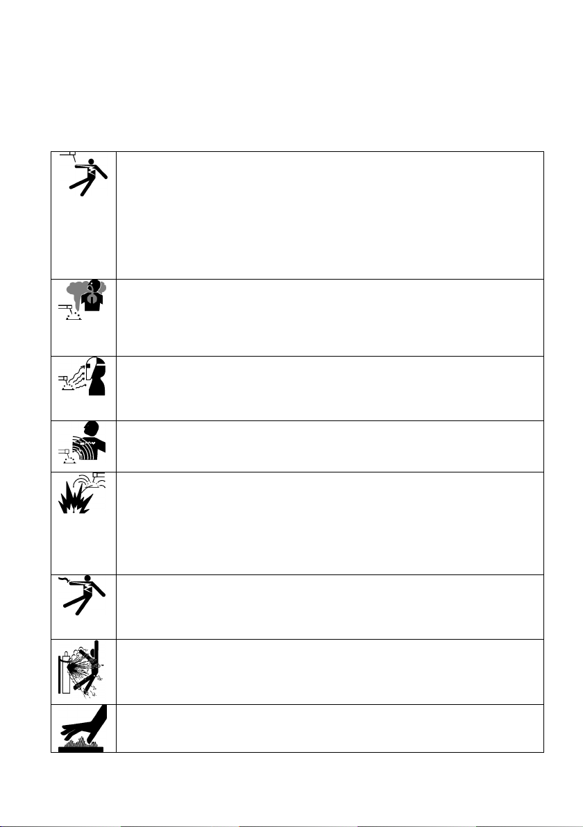
ELECTRIC SHOCK CAN KILL: Welding apparatus produce a high voltage. Do not touch the torch or welding material ELECTRIC SHOCK CAN KILL: Welding apparatus produce a high voltage. Do not touch the torch or welding material
connected when the device is turned on to the network. All the elements forming the welding current circuit can cause
electrical shock and should therefore be avoided touching them with bare hands or by wet or damaged protective
clothing. Never work on a wet surface, or use damaged welding cables.
NOTE: Removing the external time when the device is connected to the network, as well as the use of the device
with the covers removed is prohibited!
Welding cables, ground cable, earthing terminal and welding equipment should be kept in good condition, ensuring
safety.
FUMES AND GASES CAN BE DANGEROUS: In the welding process are produced noxious fumes and gases FUMES AND GASES CAN BE DANGEROUS: In the welding process are produced noxious fumes and gases
hazardous to health. Workplace should be adequately ventilated and equipped with exhaust ventilation. Do not weld in
confined spaces. Avoid inhalation of vapors and gases. The surfaces of the elements to be welded should be free from
chemical impurities such as degreasing agents (solvents) which decompose during welding to produce toxic gases.
ARC RAYS CAN BURN: It is not allowed to look directly at the eyes uncovered and exposed to the arc. Always wear a ARC RAYS CAN BURN: It is not allowed to look directly at the eyes uncovered and exposed to the arc. Always wear a
mask or helmets protected with a suitable filter. Bystanders, nearby, protected with non-combustible, absorbing radiation
screens. Protect the exposed parts of the body suitable protective clothing made of non-combustible material.
ELECTROMAGNETIC FIELDS MAY BE DANGEROUS: Electric current flowing through wires Welding produces ELECTROMAGNETIC FIELDS MAY BE DANGEROUS: Electric current flowing through wires Welding produces
electromagnetic field around it. Electromagnetic fields can interfere with pacemakers. Welding cables should be arranged
in parallel, as close as possible to each other.
SPARKS CAN CAUSE FIRE: Sparks generated during welding can cause fire, explosion and burns unprotected skin. SPARKS CAN CAUSE FIRE: Sparks generated during welding can cause fire, explosion and burns unprotected skin.
When welding should be wearing welding gloves and protective clothing. Remove or secure any flammable materials and
substances from the workplace. Do not weld closed containers or receptacles in which there were flammable liquids.
Such containers or tanks should be rinsed prior to welding in order to remove flammable liquid. Do not weld near
flammable gases, vapors or liquids. Fire extinguishing equipment (fire blankets and fire extinguishers powder or snow)
should be located close to the workstation in a conspicuous and easily accessible place.
POWER SUPPLY: Disconnect the power supply before carrying out any work, repairs on the device. Regularly check the POWER SUPPLY: Disconnect the power supply before carrying out any work, repairs on the device. Regularly check the
welding cables. If you note any damage to the wire or insulation they should be replaced immediately. Welding wires can
not be overwhelmed, touch sharp edges or hot objects.
CYLINDER could explode: Use only approved cylinders and a functioning regulator. The cylinder should be transported CYLINDER could explode: Use only approved cylinders and a functioning regulator. The cylinder should be transported
and stand upright. Protect against hot cylinders heat, and mechanical overturning. Keep in good condition all the
components of the gas system: tank, hose, fittings, reducer.
WELDED MATERIALS CAN BURN: Never touch the parts to be welded unprotected parts of the body. While touching WELDED MATERIALS CAN BURN: Never touch the parts to be welded unprotected parts of the body. While touching
and moving the welding material, always use gloves and welding pliers.
8
4. SYMBOLS 4. SYMBOLS
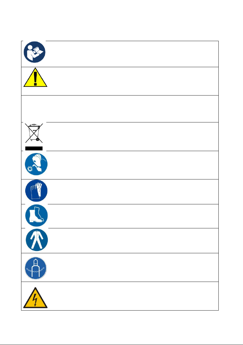
To reduce the possibility of injury, the user must first read all the instructions.
General warning sign notes for each user on the general danger. It is combined with
other instructions warning or other symbols that failure can lead to personal injury or
equipment damage.
The product complies with the requirements of European Union directives.
Disposal of electrical and electronic equipment - see DISPOSAL in this manual.
Use welding helmet or shield.
Use welding gloves.
Wear protective welding obligatory.
Wear protective welding kneading.
Secure the cylinder from falling over.
Risk of electric shock.
with
9
Function HOT START "hot start" is a temporary increase in the welding current over the set value at the moment
of arc ignition. This prevents the phenomenon of "stick electrode" in the initial phase of the welding start the whole
process easier.
ARC FORCE "arc forcing" - function for easy operation and maintenance of the electric arc, particularly in the case of
materials and / or the electrodes difficult to weld, for example. Corroded materials, niedoczyszczonych, the electrode
base, acid, etc.
Function VRD (Voltage Reduction Device) reduces the output voltage (between ground and the
electrode) to the safe level, preventing accidental shock in between spawaniami. The voltage
reduction VRD provides additional security welder and persons who are in the vicinity, especially in
an environment where there is an increased likelihood of electric shock eg .: environmental hot,
humid environment, etc.
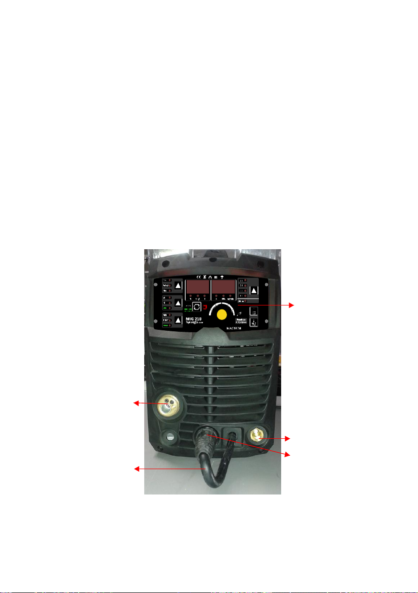
5. CONSTRUCTION AND CONTROL PANEL 5. CONSTRUCTION AND CONTROL PANEL
1
2
3
4
5
1. Control Panel.
2. Jack current, output "-".
3. Socket current, output "+".
4. Euro socket for MIG-MAG.
10
5. Cable with connector for the selection of polarization - the welding of MIG-MAG must be plugged into one of the slots according to the 5. Cable with connector for the selection of polarization - the welding of MIG-MAG must be plugged into one of the slots according to the
selected polarization.
ATTENTION:
Main power switch and a connector for connecting the protective gas is at the back of the unit.
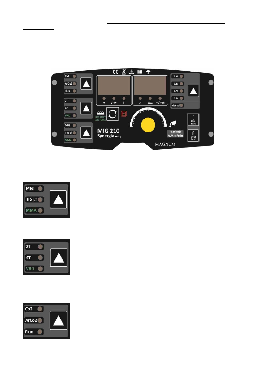
1. A selection panel welding methods:
MIG - MIG / MAG MIG - MIG / MAG
TIG Lf - TIG Lift TIG Lf - TIG Lift
MMA - welding MMA MMA - welding MMA
2. The selection panel:
2T - two-stroke engine for MIG / MAG 2T - two-stroke engine for MIG / MAG
4T - czterotakt for MIG / MAG 4T - czterotakt for MIG / MAG
VRD - the MMA VRD - the MMA
3. Panel choice of shielding gas MIG-MAG
CO2 - MAG welding CO2 shielded. CO2 - MAG welding CO2 shielded.
ArCO2 - MAG welding shield gas mixture ArCO2 or MIG welding shield Ar. ArCO2 - MAG welding shield gas mixture ArCO2 or MIG welding shield Ar.
Flux - flux-cored arc welding. Flux - flux-cored arc welding.

11
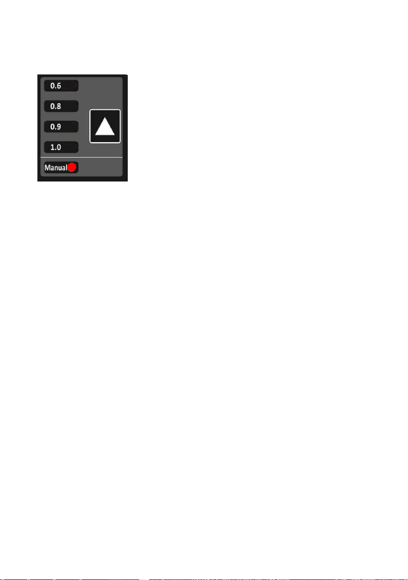
4. Panel selection of wire diameter in synergy mode or welding without synergy with manual settings.
0.6; 0.8; 0.9; 1.0 - selection of wire diameter in synergy mode for the method MIGMAG. 0.6; 0.8; 0.9; 1.0 - selection of wire diameter in synergy mode for the method MIGMAG.
Manual - MIG-MAG without synergies. Manual - MIG-MAG without synergies.
In this mode, semi-automatic adjustment is done in the traditional way.
5. Select Button
Pressing this button allows you to adjust the inductance method for MIGMAG.
For MMA values HOT START and ARC FORCE.
6. The auxiliary buttons
The test gas flow for MIG-MAG welding.
Test the extension wire for MIG-MAG.
Extension lasts until you press the button "TEST WIRE" or any other button / knob.
7. multifunctional button and knob in one.
Depending on the set welding methods you can choose:
For MIG / MAG:
-wire feed speed.
-by pressing the control, adjust welding voltage,
Lift for TIG and MMA
-set the welding current.
12
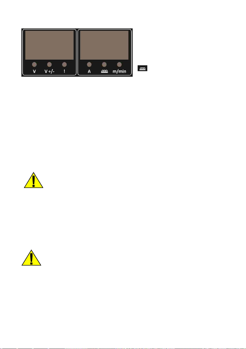
8. Set display
V - the current value of the welding voltage. V - the current value of the welding voltage.
V +/- - matching the voltage value (ranging from -10 to V +/- - matching the voltage value (ranging from -10 to
+10).
! - warning about the activation of the safety ! - warning about the activation of the safety
device or failure.
AND - the current value of the welding current. AND - the current value of the welding current.
-matching inductance value (ranging from
-10 to +10).
m / min - the wire feed speed. m / min - the wire feed speed.
6. KIT CONTENTS 6. KIT CONTENTS
The following items should be included:
welding machine x 1 pc.
Work cable MIG / MAG x 1 pc.
Work cable MMA x 1 pc.
Cable to the common terminal x 1 pc.
Attention!
For the safety of children should not be left freely accessible parts of the packaging
(plastic bags, cardboard, polystyrene, etc.). Risk of suffocation!
7. USE 7. USE
7.1 Connecting to the network
Before switching the device to the mains, check the size of the voltage, phase and
frequency.
Parameters supply voltage are given in the technical specification section of this manual and on the
rating plate.
Check the grounding wire connection device to the mains. Make sure the power network can ensure
coverage of the power demand for the input of the device under its normal operation.
Fuse size and parameters of the power cord are given in the technical data of this manual.
13
The supply network should have a stable voltage. Cross-section of the supply lines should not be
less than 2.5 mm.
Devices which do not have power plugs connected by. tips listed below.
Connecting and sharing the power cord and the plug should be made by a qualified
electrician.
Insulated wire of yellow-green is grounded and should always be connected to the outlet marked
earth, regardless of whether there is power supply 230 [V] and 400 [V].
Earth symbol.
7.2 Fitting wire welding - MIG / MAG welding.
ATTENTION! Before all work carried out on the unit, unplug the power cord.
1. Make sure that the device is not connected to the mains. 1. Make sure that the device is not connected to the mains.
2. Check that the ground wire is terminated by a clamp or screw. 2. Check that the ground wire is terminated by a clamp or screw.
3. Plug the cable connected to the mass located on the front panel output jack of the correct polarity, 3. Plug the cable connected to the mass located on the front panel output jack of the correct polarity,
push and twist. A loose connection causes premature firing pin plug and socket current. The
ground wire in the MIG-MAG typically connect to the "- '', when using self shielding wire to the" + ".
After plugging the cable mass in selected slot in the second empty slot next to, insert connector
hanging on the built-in cable. It is necessary to close the circuit welding.
Without the plug plugged into one of the output jacks (plus or minus) the device will not weld!
4. Before putting the welding wire make sure the appropriate armor is established next to the 4. Before putting the welding wire make sure the appropriate armor is established next to the
appropriate diameter and type of electrode wire. To facilitate the manufacture of armor guiding them
label the appropriate colors. For a wire diameter
0.6 to 0.8 mm, a blue color, the wire having a diameter of 1.0 ÷ 1.2 mm, color red, and for a wire electrode
with a diameter of 1.6 mm color yellow. Welding alloy steels and
14
aluminum, Teflon armor use. For the welding of low carbon steel, low alloy steel, copper, bronze, etc., Are
used with spiral metal armor. It should be remembered accessories from the welding torch in the contact
tip to the appropriate species and the filler wire diameter.
5. Plug the cord of welding "Euro-plug" to enter into the socket (socket euros) on the front panel of the 5. Plug the cord of welding "Euro-plug" to enter into the socket (socket euros) on the front panel of the
welding machine, then tighten the nut by hand until it stops.
7.3 Inserting the wire electrode.
1. Make sure that the roller mounted in the drive train correspond to the type and diameter 1. Make sure that the roller mounted in the drive train correspond to the type and diameter
the introduced wire. If the difference roll groove to the diameter of the wire electrode fit groove by the
reversal or replacement of the roll. For steel wire, use of rollers with V-shaped grooves, and the
aluminum wire with the groove in the U-shaped
2. Place the spool of wire electrode on the spool mounting mechanism, paying attention to 2. Place the spool of wire electrode on the spool mounting mechanism, paying attention to
wire unwinding direction was consistent with the direction of the entrance to the wire drive unit.
NOTE - The nut body has a spool LEFT THREAD.
3. Lock the spool before falling, by tightening the nut on the body of the reel. 3. Lock the spool before falling, by tightening the nut on the body of the reel.
4. The end of the wire wound on the spool, flatten or cut off the bent section, then 4. The end of the wire wound on the spool, flatten or cut off the bent section, then
file off, so that was not sharp.
5. To allow the insertion wire feeder release the pressure feed rollers. 5. To allow the insertion wire feeder release the pressure feed rollers.
6. End of the wire inserted into the guide at the rear of the tray and perform 6. End of the wire inserted into the guide at the rear of the tray and perform
it above the drive rollers and plug to the port leading to the welding torch.
7. Push wire in the grooves of the drive rollers by tightening the clamp. 7. Push wire in the grooves of the drive rollers by tightening the clamp.
8. Remove gas nozzle and contact tip, unscrew. 8. Remove gas nozzle and contact tip, unscrew.
9. Switch on the device. 9. Switch on the device.
10. Handle develop so that it is in a straight line, then press the button on the handle or 10. Handle develop so that it is in a straight line, then press the button on the handle or
WIRE TEST button until the emergence of a wire in the outlet (approx. 20 mm), release the button.
11. Screw the contact tip, replace the gas nozzle. 11. Screw the contact tip, replace the gas nozzle.
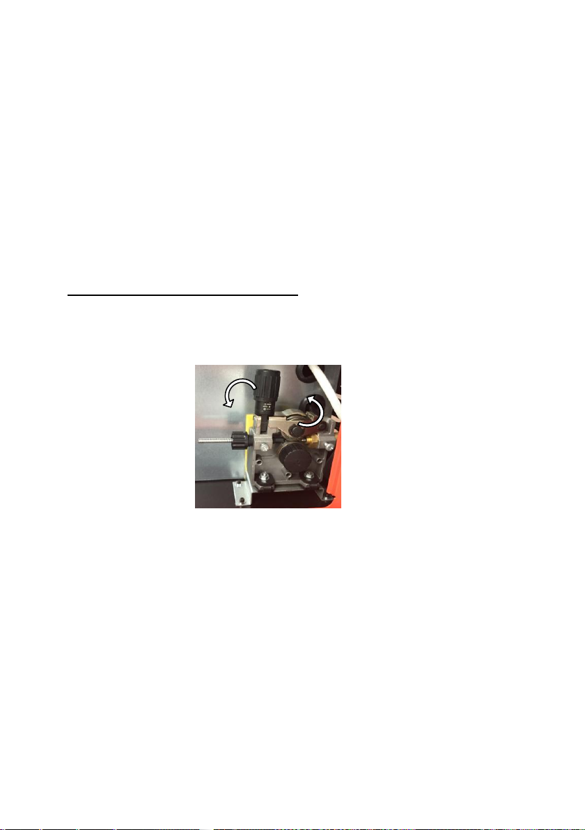
12. Adjust the contact pressure feed roller by rotating the platen knob. Too small force12. Adjust the contact pressure feed roller by rotating the platen knob. Too small force
pressure, will cause slippage of the drive roller. Too much contact force, increases the resistance of
administration and the deformation of the wire, which in turn can cause the cutting.

15
7.4 Connection of protective gas.
1. The cylinder with a suitable protective gas should be set to a semi-automatic shelf (if present) or the wall 1. The cylinder with a suitable protective gas should be set to a semi-automatic shelf (if present) or the wall
and prevent it from tipping over, securing it to the support by means of a chain.
2. Remove the protective cap and the second valve unscrew the bottle to remove any impurities. 2. Remove the protective cap and the second valve unscrew the bottle to remove any impurities.
3. Install the regulator so that the gauges were in the upright position. 3. Install the regulator so that the gauges were in the upright position.
4. Combine with semi-cylinder (outlet of the regulator nozzle clip) corresponding hose. Connector for 4. Combine with semi-cylinder (outlet of the regulator nozzle clip) corresponding hose. Connector for
connecting the protective gas is placed at the rear.
5. Unscrew the regulator valve just prior to welding. After completion of welding, spin the cylinder valve should 5. Unscrew the regulator valve just prior to welding. After completion of welding, spin the cylinder valve should
be.
6. Avoid welding in the open air or within - a blast of air can disrupt the flow of the shielding gas and 6. Avoid welding in the open air or within - a blast of air can disrupt the flow of the shielding gas and
liquid metal strip protection.
7.5 MIG / MAG
Synergy MIG device 210 is a device easy synergistic effect, i.e. the user chooses the
diameter of welding wire used, and the device automatically adjusts the other parameters. The user is
able to control the wire speed and adjust the inductance and the welding voltage.
Increasing the voltage increases the weld penetration (penetration depth) and elongation of
the arc. When welding at positions pułapowych wall and can reduce the welding voltage, the
performance of joint filler to obtain a smooth face, voltage can be increased welding current.
Higher inductance (soft arc) results in a wider weld pool and less spatter. While the lower
inductance produces a stable, concentrated arc. Generally, you must set a hard arc welding current
into a smaller, softer and choose the larger arc welding current.
1. Switch on the device - ensure that the function is selected MIG (MIG lit the lamp).
2. Press the selection of wire diameter highlighted until the desired diameter of the welding wire (0.6; 0.8;
0.9; 1.0).
The device automatically selects the parameters to set the wire diameter.
3. Depending on the thickness of the welded material selected control dial the wire feed speed.
In addition, if necessary, you can adjust the device by changing the voltage value of the welding
current and inductance.
4. To adjust the voltage, press the control knob - LED display on the left of the symbol " V +/- " will 4. To adjust the voltage, press the control knob - LED display on the left of the symbol " V +/- " will 4. To adjust the voltage, press the control knob - LED display on the left of the symbol " V +/- " will
flash. Then adjust knob device. Voltage regulation is possible in the range of about ± 10%.
After 4 seconds of inactivity will switch the unit on the wire feed speed.
5. To adjust the inductance press inductance choice. The left display will show the symbol Ind light
and illuminate the symbol inductance. Then, knob, set the desired range within ± 10%.
After four seconds of inactivity the display returns to the wire feed speed and tension.
16
MIG 210 Synergy easy has the ability to manually set the parameters which takes place as in the
case of traditional semi-automatic welding.
To this end, the choice of diameter of the wire should be pressing the Start button, select 'Manual. "
Then the wheel to set the wire feed speed - in the entire speed range.
Pressing the knob causes the switching device to the voltage regulation
- the symbol V +/- It will be highlighted. Then, set the dial to the desired - the symbol V +/- It will be highlighted. Then, set the dial to the desired - the symbol V +/- It will be highlighted. Then, set the dial to the desired
voltage value. Adjustment is possible in the full range of voltages. After
about 4 seconds,
or again, the knob is pressed, the device will switch on
the feed speed of the wire. In manual mode - the same as the
synergistic - select the type of shielding gas and adjust inductance.
7.6 Practical recommendations MIG / MAG welding.
Butt welds in the flat position must be carried out using "push" for thin components and
technology "pull" for items thicker. Butt welds in vertical position for thin elements should be done
from top to bottom. Fillet welds in position nabocznej should be carried out using "push", but with an
additional tilt the torch in a plane perpendicular to the direction of welding. In the case of filling the
wide grooves in the flat position
or the vertical end of the handle must be performed
lateral swinging movements. During welding, the welding gun should be conducted at a right angle
relative to the parts to be welded -If high helix angle may result in sucking air into the liquid metal
angle (from the vertical holder should be ≤ 10 °). Long arc welding reduces the depth of penetration -
the seam is wide and flat, and is accompanied by increased weld spatter.
Short arc welding (with the same current density) increase the depth of penetration - the weld is narrower,
and the spatter material becomes smaller. The welding speed is a parameter output at a given current
intensity and arc voltage, and maintaining the correct shape of the weld bead, and when the welding speed
may even be slightly changed, change the current or the arc voltage. The increase welding speed makes the
weld is narrower and decreases the depth of penetration, and with further increase in the face of flooding
occur. The largest welding speed, without undercuts, can be obtained by increasing the stick electrodes and
the inclination of the object up and down or tilt in the direction of the welding torch. Small welding speeds
cause that increases the depth of penetration, face width and height of the riser.

17
Excessive lengthening or shortening the arc can
cause unstable arc glow and poor weld quality.
L1, L2 - arc length
The depth of penetration is also significantly impact
the direction of welding - carrying the torch.
H1, H2 - the depth of penetration
The protective gas guards determines the efficiency of the welding area, but also of a process for transferring the
metal in the arc, the welding speed and the shape of the weld. Inert gases argon and helium, although perfectly
protect the molten weld metal against access of air, are not appropriate for all applications GMA welding. By mixing
in the appropriate proportions of helium or argon and a chemically active gas obtained by changing the nature of
metal transfer the arc to increase arc stability and there is possibility to influence on metallurgical processes in the
weld seam. At the same time it is possible to significantly reduce or completely eliminate splash.
protective gas Chemical action welded metal
ar inert Basically, all metals except for carbon steels
He inert Al, Cu, Cu alloys, Mg alloys, ensured high heat input welding
20-80% Ar + He inert Al, Cu alloys, Cu, Mg, there is provided a large heat input welding, low
thermal conductivity gas
25-20% Ar + N 225-20% Ar + N 2 reducing Copper welding with high heat input arc glow better than the arc shield 100% N 2Copper welding with high heat input arc glow better than the arc shield 100% N 2
Ar + 12% O 2Ar + 12% O 2 weakly oxidising Recommended mainly for welding stainless steels and alloy steels
Ar + 3-5% O 2Ar + 3-5% O 2 oxidising Recommended for welding carbon steel and low-alloy steel
WHAT 2WHAT 2oxidising Recommended only for welding low carbon steel
20-50% Ar + CO 220-50% Ar + CO 2 oxidising Recommended only for welding carbon steel and low-alloy
steel
Ar + 10% CO 2 + 5% O 2Ar + 10% CO 2 + 5% O 2Ar + 10% CO 2 + 5% O 2Ar + 10% CO 2 + 5% O 2 oxidising Recommended only for welding carbon steel Low-alloy and
opowych
WHAT 2 + 20% O 2WHAT 2 + 20% O 2WHAT 2 + 20% O 2WHAT 2 + 20% O 2WHAT 2 + 20% O 2 oxidising Recommended only for welding low carbon steel and low-alloy
90% He + 7.5% Ar +
2.5% CO 22.5% CO 2
weakly oxidising Corrosion resistant, short-arc welding
60% He + 35% Ar + 5%
WHAT 2WHAT 2
oxidising Low alloyed steels, high-impact, short-arc welding

18
7.7 Welding MMA
The device described in this guide is able to weld with coated electrodes hot melt.
To weld MMA, select on the control panel function MMA.
After selecting the MMA can immediately adjust the welding current. Adjustment is done by turning the
knob.
When welding method MMA are also features such as Hot Start and Arc Force. To set
facilitates arc ignition - Hot Start - press the "HOT START".
The left display will show the symbol Hot.
Then, the knob can be set to function in the range of 0 ÷ 10%.
After approximately 4 seconds if the display is changed to the regulation of the welding current.
Double-press the same button rearranges the unit to adjust the function of Arc force. The display
shows the symbol For. Then, the knob can be set to function in the range of 0 ÷ 10%.
After approximately 4 seconds if the display is changed to the regulation of the welding current.
These parameters can be adjusted at any time.
Values for welding current, the polarity of, the requirements of the drying usually given by manufacturers of
electrodes on the packaging.
In the current slot (plus and minus) to plug welding wires.
Ground wire hook to the work piece, the wire electrode wear electrode.
To avoid splashes during welding and to obtain good quality welds, must comply with the instructions given
by the manufacturer of the electrodes: welding current, welding positions, time and drying temperature. This
is of particular importance in the case of electrodes of alkaline or acidic buffer zone (EB, EA)
The basic parameters of the welding MMA:
-welding current,
-welding speed,
-thickness, the type of the electrode and the work piece.
The amount of current is adjusted so that it could probably ignite the arc, and in the course of welding was steady and stable.
For example, the electrode "Pink 6012" for a given diameter needs:
2.0 mm / 40 to 60 A, 2.5 mm / 50 to 70 A 3.25 mm / 70 to 110 A, 4.0 mm / 110 ÷ 160 A,
5.0 mm / 160 ÷ 220 A.
19
7.8 TIG LIFT
The device described in this document can be applied to TIG welding LIFT. You will need to acquire
the holder intended for this method - a handle provided with a mechanical protective gas valve
arranged in the handle.
In order to obtain high quality, convenience and economy TIG welding, we recommend purchasing a
contactless arc ignition, brand MAGNUM series TIG TIG THF or VIPER.
To weld TIG LIFT should:
•Insert the welding cable plugs into the corresponding sockets and lock them (to handle mass (+), TIG
torch to the (-)).
•Connect a gas TIG torch to a source of protective gas (argon gas).
•Using the grounding clamp connect the welding cable to the workpiece mass.
•Check the condition of tightening the tungsten electrode.
•Plug the power cord into a power outlet.
•A power switch turn on the power supply device.
•Select the control panel function "TIG".
•With the knob "adjustment" to set the required value of the welding current.
•Unscrew the valve on the gas pressure regulator and protective handle TIG, it will cause the flow of protective gas.
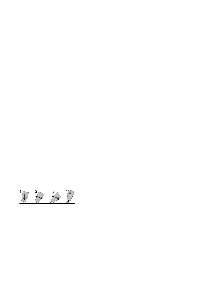
TIG arc infusible by rubbing the electrodes of the welding. Lightly touch the electrode of the welded
materials (1) to break the electrode from the welded material by tilting the holder in such a way that the
gas nozzle touches the material (2 and 3), causing ignition of the arc. Straighten the handle (4) and begin
welding. To complete the welding holder should "break" from the work piece.

20
8. CLEANING AND MAINTENANCE 8. CLEANING AND MAINTENANCE
Degree of protection of this device is IP21S, so, do not use the unit in the rain, or expose it to
moisture.
ATTENTION:
A device based on electronic components. Grinding and cutting in the vicinity of
the welding device can contaminate the swarf inside the device, thus leading to
damage. The above-mentioned damage is not covered by warranty! In the case of
having to work in such an environment must be made to clean the machine by blowing
compressed air inside of the welder.
To extend the service life and reliable operation, observe a few rules:
1. The device should be placed in a well-ventilated room, where there is a free circulation of air. 1. The device should be placed in a well-ventilated room, where there is a free circulation of air.
2. Do not place the device on a wet surface. 2. Do not place the device on a wet surface.
3. Use a wire diameter and a weight of the spool in accordance with disposed on the table. 3. Use a wire diameter and a weight of the spool in accordance with disposed on the table.
4. The gas cylinder protective set stable and secure with chain against the possibility of tipping over. 4. The gas cylinder protective set stable and secure with chain against the possibility of tipping over.
5. Check the condition of technical equipment and welding cables. 5. Check the condition of technical equipment and welding cables.
6. Remove all flammable material from the welding area. 6. Remove all flammable material from the welding area.
7. Welding use suitable protective clothing: gloves, lab coat, shoes, a mask or helmet. 7. Welding use suitable protective clothing: gloves, lab coat, shoes, a mask or helmet.
When planning the maintenance of the device should take into account the intensity and operating conditions. Proper
use of the equipment and its regular maintenance will avoid unnecessary disruption and downtime.
Daily:
• Purify the handle by weight, and the gas nozzle chips, means lubricate against frangibility.
•Check whether the cables are correctly connected.
•Check the condition of the pipes. Replace damaged cables.
• Make sure that the device around the free flow of air.
• Replace or repair damaged or worn parts.
Every month?
•Check the condition of the electrical connections inside the source.
• Oxidized surfaces should be clean and tighten loose parts.
•Clean the inside of the device by means of compressed air.
Table of contents
Other Spaw Welding System manuals

Popular Welding System manuals by other brands

CEMONT
CEMONT SMARTY TX 220 Alu Safety Instructions for Operation and Maintenance

Lincoln Electric
Lincoln Electric LF-72/74 Service manual

Arcoweld
Arcoweld Arcostick MMA 160 Minespec Operator's manual

voestalpine
voestalpine Bohler Welding URANOS 1500 TLH instruction manual

LESITE
LESITE LST-WP2 manual

Titanium
Titanium Easy-Flux 125 user manual


Oerlikon
Oerlikon CITOARC 1450 FORCE Safety instruction for use and maintenance

Lincoln Electric
Lincoln Electric VANTAGE 400 brochure

Thermal Dynamics
Thermal Dynamics PAK Master 150XL Service manual

Leister
Leister ALLIED VARIMAT V2 manual

SincoSald
SincoSald NOVATIG 325 DC instruction manual

Lincoln Electric
Lincoln Electric COOLARC 46 Operator's manual