HBS CD 2301 User manual

CD 2301
Power Unit
NorthAmerica
92-12-0231A
Operating Manual
2010

ii
ii CD2301OrderNo.BA92-12-0231A Issue05.01.10
CD 2301 Operating Manual, Issue 01/2010 Order No. BA 92-12-0231A
Translation of the Operating Manual
Customer Service in Germany:
HBS Bolzenschweiss-Systeme GmbH & Co. KG
Felix-Wankel-Strasse 18
85221 Dachau / Germany
Phone +49 (0) 8131 511-0
Fax +49 (0) 8131 511-100
E-mail [email protected]
Web www.hbs-info.com
Copyright:
The information contained herein may not be copied, reproduced, adapted,
merged, translated or used without the prior written consent of the copyright
owner.
Adaptations, errors and technical modifications reserved without prior notice.
©HBS Bolzenschweiss-Systeme GmbH & Co. KG

iii
CD2301OrderNo.BA92-12-0231A Issue05.01.10 iii
Dearcustomer,
Thankyouvery muchforpurchasing apowerunit fromHBSBolzenschweiss-
Systeme.
We from HBS wish you always successful working with this stud welding unit.
We ask you to observe the following points:
– Store the operating manual in a way that it can always be accessed by the
operator.
– Letthe operator signbefore startingup that hehas read and completely under-
stoodtheoperatingmanual.
– This operating manual applies only to this stud welding unit.
– Protectthe stud welding unit fromunauthorized use.
– Thestud welding unit must onlybe operatedby trainedpersonnel.
– Let an electrician check whether the wall sockets where you want to connect the
relatedstudweldingunit,areproperlyfusedandgrounded.
– Informourcustomerserviceincaseofmalfunction.
– In case of accident, inform a physician and the responsible official body.
THREATTOLIFE!
Persons fitted with a pace maker must not operate the stud
welding machine.
MAGNETICFIELDS!
During stud welding, strong electro-magnetic fields are
generated. Do not weld in the vicinity of the electrical
equipment which could be affected.
Safety instructions are a delicate subject. Anybody who handles a stud welding
unit, whether it is the welding gun or the power unit, should be familiar with them,
becauseimproper use ofstud welding unitscan be dangerous to life.
For your own sake you should know the safety instructions for operating your HBS
stud welding units inside out.
In addition to the protection of your health and the capital value of the enterprise, the
safety instructions are intended to clarify any responsibilities, which arise from
ownershipandoperationoftheequipment.
Thischapteroftheoperatingmanualoffersyouclearandeasytounderstandinformation
forthe safe operationof your HBS stud weldingunit.

iv
iv CD 2301 Order No. BA 92-12-0231A Issue 05.01.10
Your power unit may differ in some details from the captions in this manual. This has
noeffectonthe operationofthewelding machine.
Shouldyouhavequestionsaboutthismanualorincaseyouwanttoordersomemore
copies,please providethe order number listed inthe footline.
Importantreminder:
Dataandinformationhereinwerecollectedwithgreatestcare.Althoughwedidourvery
besttocorrectlyupdateanyinformationuptothetimeofdelivery,thereisnoguarantee
inrespectof errors.
If you should detect errors or mistakes right in this manual, please contact us:
HBS Bolzenschweiss-Systeme GmbH & Co. KG
Felix-Wankel-Strasse18
85221Dachau/Germany
Afeedback blankis provided in the appendix.

CD2301OrderNo.BA92-12-0231A Issue05.01.10 v
Table of Contents
Table of Contents
1 General .............................................................................................7
1.1 Guide to this Operating Manual .................................................................... 8
1.2 Safety Symbols ............................................................................................ 9
1.3 General Safety Instructions ........................................................................ 10
1.4 IntendedUse .............................................................................................. 10
1.5 Transportation, Packaging, Storage ........................................................... 11
1.6 Accompanying Documents ........................................................................ 11
1.7 Markings ..................................................................................................... 12
2 Delivery...........................................................................................13
3 Starting-up .....................................................................................14
3.1 Requirements of Workplace ...................................................................... 14
3.2 Connecting the Power Unit to the Primary Power Supply .......................... 15
3.3 Connecting the Welding Gun to the Power Unit ......................................... 16
3.4 Ground Connection .................................................................................... 17
3.5 Change Working Place .............................................................................. 17
4 Function .........................................................................................18
4.1 Components of the Power Unit .................................................................. 18
4.2 Keyboard and Display ................................................................................ 19
5 Stud Welding Procedure...............................................................20
5.1 Safety Instructions...................................................................................... 20
5.2 Functional Principle of Stud Welding.......................................................... 23
5.2.1 Contact Stud Welding ............................................................................................ 23
5.2.2 GapStud Welding.................................................................................................. 24
5.3 Welding Preparation................................................................................... 25
5.4 High-strength Welds................................................................................... 25
5.5 Determination of Welding Parameters ....................................................... 25
5.6 Switching on the Power Unit ...................................................................... 27
5.6.1 Adjustingthe ChargingVoltageof Capacitors......................................................... 28
5.6.2 Library Mode .......................................................................................................... 29
5.7 Welding Procedure .................................................................................... 29

vi CD2301OrderNo.BA92-12-0231A Issue05.01.10
Table of Contents
5.8 Checking the Quality of the Weld ............................................................... 30
5.8.1 VisualInspection ................................................................................................... 31
5.8.2 BendingTest.......................................................................................................... 32
5.8.3 Arc Blow Effect ...................................................................................................... 34
5.9 Malfunctions and CorrectiveActions .......................................................... 35
5.10 Welding Elements ...................................................................................... 36
6 Switching off the Power Unit ........................................................38
6.1 Temporary Switching off............................................................................. 38
6.2 Disposal ..................................................................................................... 38
7 Care and Maintenance ..................................................................39
7.1 Safety Instructions...................................................................................... 39
7.2 Regular Maintenance Operations ............................................................... 39
7.3 Tools to be Used......................................................................................... 39
7.4 Open the Power Unit .................................................................................. 40
8 Appendix ........................................................................................41
8.1 Technical Data............................................................................................ 41
8.2 Spare Parts ................................................................................................ 42
8.3 Circuit Diagram .......................................................................................... 56
8.4 EnvironmentallyAdmissible Disposal......................................................... 57
Glossary .........................................................................................58
Regulations and Standards ..........................................................59
Further Instructions....................................................................... 61
Guarantee Clauses ........................................................................62
Confirmation ..................................................................................63
Feedback........................................................................................64
Service & Support ......................................................................... 65
Index ...............................................................................................66

CD2301OrderNo.BA92-12-0231A Issue05.01.10 7
1 General
Persons addressed by this operating manual
This operating manual is written for operators, personnel of the end user, and authorized
service technicians. It provides you with all necessary information to operate the power
unit.
Required user qualification
The power unit must only be operated by qualified personnel.
Let the power unit only be operated by persons who
– are qualified through a suitable training according to the current standards (see
appendix),
– are properly instructed,
– are physically and intellectually suitable,
– can be expected to reliably fulfill the requested job.
What else must the owner observe?
Make sure that this operating manual is always in reach of the stud welding unit.
Read the entire manual before operating the power unit.
Strictly observe the safety instructions.
Before starting up the power unit, let the operator sign the confirmation that he/
she has read and fully understood the operating manual (see appendix).
Do not commence stud welding until you have understood all operating
processes.
Contact us if there are any doubts on certain operating procedures.
Protect the power unit against unauthorized use.
Inform our service in case of malfunction.
Based on this operating manual, a company specific work order, as well as a company
specific maintenance instruction must be drawn up. The company specific work order
must consider the special user conditions in your company.
Make sure that operators of the welder are provided with and wear personal protective
equipment, e.g. protective goggles, gloves, shoes, ear protection etc.
Owners and operators make sure that the power unit is only used as directed.
During any activity such as transportation, set-up, (re-)assembly, production,
maintenance etc. observe the information given in this operating manual.
1 General

8 CD2301OrderNo.BA92-12-0231A Issue05.01.10
1.1 Guide to this Operating Manual
This operating manual provides you with the following information
"Delivery" in Chapter 2
"Starting-up" in Chapter 3
"Functional Principle" in Chapter 4
"Stud Welding Process" in Chapter 5
"Switching off the Power Unit" in Chapter 6
"Care and Maintenance" in Chapter 7
Technical Data and much more in Appendix
THREAT TO LIFE and risk of serious health and material damage in
case of improper use of the power unit. Observe all notes in this
operating manual.
Note for qualified operators (see chapter 1).
All instructions contained in this manual must also be observed
by qualified operators.
The welding process and the sequence of procedures to carry
out a weld are described in chapter 5.
1 General
1.1 Guide to this Operating Manual
CD2301OrderNo.BA92-12-0231A Issue05.01.10 9
1.2 Safety Symbols
Symbols and markings used in this operating manual mean:
Threat to life or risk of personal injury
Risk of material damage
Ban for persons fitted with a pace maker
Warning of dangerous electrical voltage
Warning of electromagnetic fields
Wear protective clothes
Wear protective goggles
Wear ear protection
Additional tips for operation and service safety
Prompt
– List
1 General
1.2 Safety Symbols

10 CD2301OrderNo.BA92-12-0231A Issue05.01.10
1.3 General Safety Instructions
Improper operation of the power unit is LIFE-THREATENING!
Threat to life
– by electric shock and arc
– by toxic vapors and airborne particles
– by red-hot metal spatters (fire risk)
– by blow-up of explosive gases and materials
– by strong magnetic fields for persons fitted with a pace maker
In addition, through improper use damage to the stud welding unit
and to material can be caused. For details, see chapters 1, 3 and 5.
1.4 Intended Use
Warning: Unauthorized interference with the stud welding unit
as well as unauthorized alteration of the stud welding unit are
prohibited and result in complete cancellation of any guarantee
and liability claims against HBS.
Operation of the power unit is only allowed with HBS welding
guns, this clause is also part of ”use as directed”.
The power unit is intended to weld welding elements according to actual standards (see
chapter 5 and appendix). Any other use is regarded as not used as directed. The
manufacturer is not liable for damages resulting from the stud welding unit not used as
directed. Any risk is carried by the user.
The power unit is designed according to specific standards and accident prevention
regulations. Basics are European Union guidelines and in Germany valid standards.
Pleasenotethatinyourcountryadditionalstandardsandsafetyconditions(especially
rulesforaccidentprevention)maydifferfromthestandardsmentionedinthisoperating
manual.The power unit was manufactured to the latest developments in technology and
is regarded as safe to operate (place of operation see section 8.1).
The welding guns C 08 and CA 08 can be connected to the HBS power unit
CD 2301. For details please contact the HBS customer service (address see page ii).
Check in any case the operating manual of the HBS welding gun whether this
power unit can be used.
Observing the operating manual of the used welding gun is also part of the ”use as
directed”.
1 General
1.3 General Safety Instructions

CD2301OrderNo.BA92-12-0231A Issue05.01.10 11
1.5 Transportation, Packaging, Storage
HBS delivers products in a specific transport package.
Save the undamaged packing. Ship and transport the device only in its original
packing.
Right before delivery, the power unit is once again checked for proper functioning and
a control mark is attached. When receiving the delivery, check everything for damages
and completeness. If damages occurred during transportation or components are
missing, inform the manufacturer or the haulier immediately (see page ii).
Proper functioning of the power unit can only be checked before starting-up by visual
inspection (visible damage).
The following items are to be observed if the power unit is not to be put into operation
immediately after delivery.
– The power unit must be stored in a secure place
– The power unit must be protected against humidity, dust, metallic dirt.
– Storage temperature: -5 °C to +50 °C
– Relative humidity: 0% to 50% at +40 °C
0% to 90% at +20 °C
If you resell the power unit, please provide us with the name and postal address
of the new owner so that we can advise them of any changes to the operating
manual.
1.6 Accompanying Documents
In addition to this operating manual, you must observe the operating manual of the
welding gun as well as applicable accident prevention and safety instructions.
1 General
1.5 Transportation, Packaging, Storage
12 CD2301OrderNo.BA92-12-0231A Issue05.01.10
1.7 Markings
There are various markings and safety symbols attached to your power unit (see
section 8.1).
Make sure that all markings remain clearly visible.
Type plate
The type plate contains the following data:
Manufacturer
Type
Order No./Serial No.
Primary voltage
Fuse
Power consumption
Cooling class
Protection class
Date
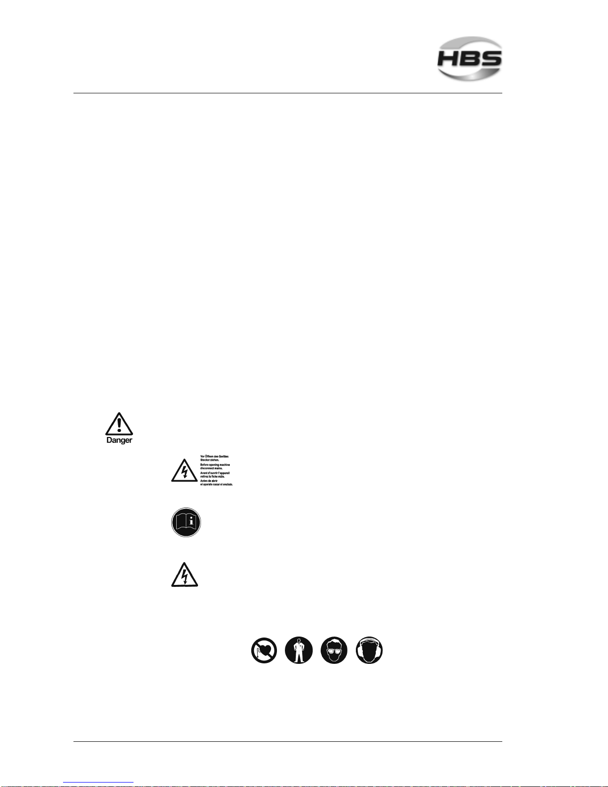
Safetysymbols
Replace illegible or damaged markings
Before opening machine disconnect mains
Observe operating manual
Warning of dangerous electrical voltage
Secure the following safety symbols in the area of welding place:
1 General
1.7 Markings

CD2301OrderNo.BA92-12-0231A Issue05.01.10 13
2 Delivery
The basic equipment of your power unit contains the following components:
No. of pieces Part Type Order No.
1 Power unit CD2301 92-12-0231A
1 Operating manual CD 2301 BA 92-12-0231A
2 Delivery

14 CD2301OrderNo.BA92-12-0231A Issue05.01.10
3 Starting-up
In this chapter you learn what to observe during setting-up and starting-up of the power
unit.
3.1 Requirements of Workplace
Vapors and airborne particles may occur during stud welding
operations. Especially with surface treated materials, toxic
vapors may be produced.
Ensure that a fume extraction is available and that the room is adequately
ventilated according to accident prevention regulations.
If possible, do not weld in rooms which are lower than 3 meters.
Special regulations apply for confined rooms, according to accident prevention
regulations of the official bodies (see appendix).
Weld only in adequate distance from combustible articles or liquids.
Before you start welding, remove any combustible articles or liquids in vicinity of
the workplace.
Make sure that a fire extinguisher is within reach.
Never weld in rooms exposed to risk of explosion.
Do not set-up the product in the vicinity of any apparatus or equipment which is
sensitive to welding spatter.
Do not set-up the product in the vicinity of any apparatus or equipment which is
sensitive to magnetic fields.
Set-up the power unit:
– on a stable, clean, and level surface
– so that no-one is influenced or injured by welding spatter
– so that all cables and primary lines are protected from being damaged
– so that nobody will trip or fall over the cables or connection lines.
Ensure that air is able to circulate freely through the housing.
If heat is built-up inside the housing caused by bad air circulati-
on, the stud welding unit will be seriously damaged.
3 Starting-up
3.1 Requirements of Workplace

CD2301OrderNo.BA92-12-0231A Issue05.01.10 15
Secure the following safety symbols in the area of welding place:
THREAT TO LIFE to persons fitted with a pace maker
Strong electro-magnetic fields occur in the vicinity of the stud welding
unit during welding. Such fields may affect the proper function of a
pace maker. Thus persons equipped with a pace maker must not
operate the stud welding unit and must not stay in its vicinity during
welding.
During the actual welding process, you must expect red-hot welding
spatters, possibly liquid spatters, a flash, and a loud bang > 90 dB (A).
Alert any colleagues who are occupied in the vicinity of the welder.
Wear your personal protective equipment according to actual
standards (see appendix).
3.2 Connecting the Power Unit to the Primary Power Supply
Compare the primary voltage specified on the type plate with the voltage provided
by your primary power supply. The type plate is located on the backside of the
power unit.
Never connect the welder to a power supply with a voltage
different from the voltage indicated on the type plate.
Check the current consumption specified on the type plate with the fuse rating of
your primary power supply.
Have an electrician check whether the outlet to which you want to connect the
power unit is correctly grounded.
Switch off the power unit.
Insert the primary plug into the checked outlet.
3 Starting-up
3.2 Connecting the Power Unit to the Primary Power Supply
16 CD2301OrderNo.BA92-12-0231A Issue05.01.10
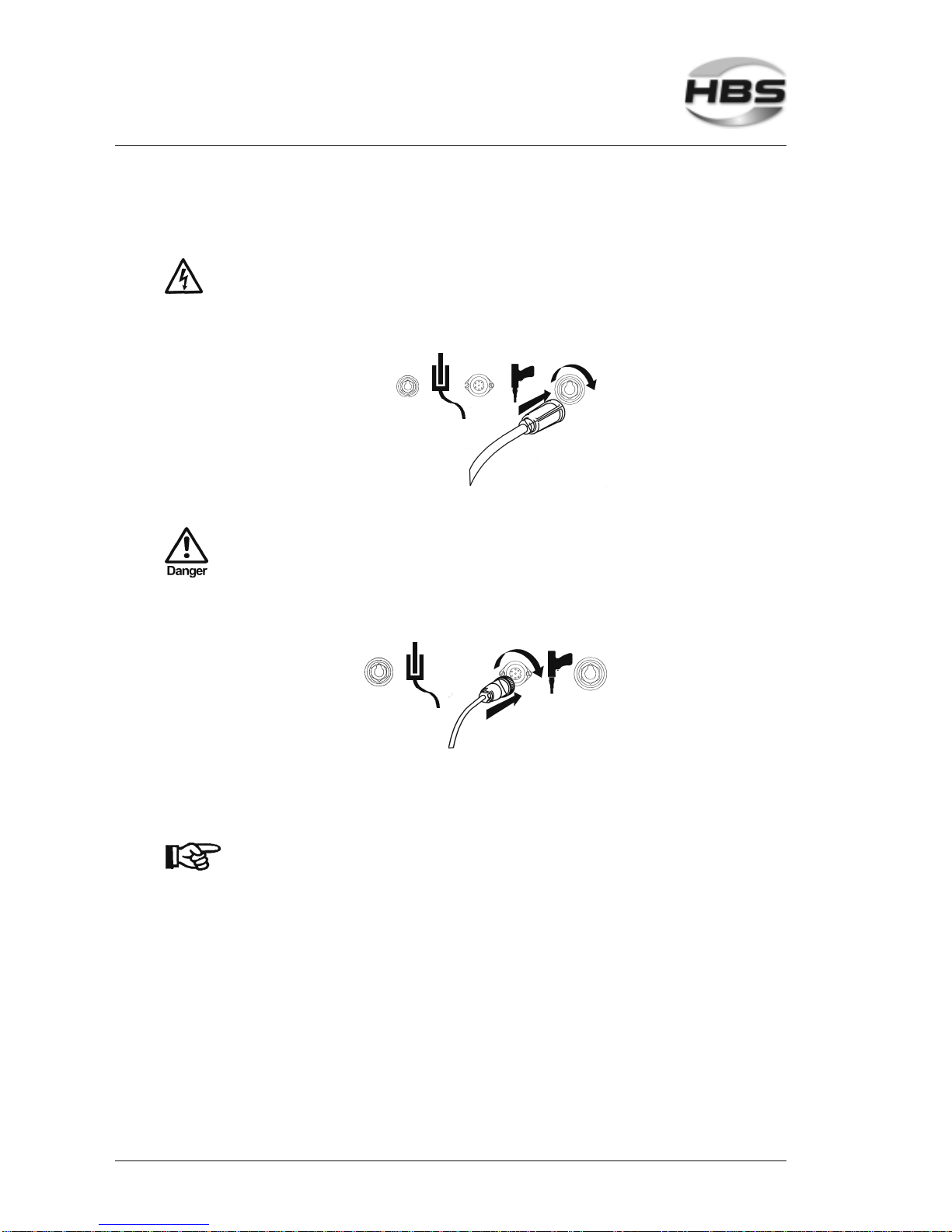
3.3 Connecting the Welding Gun to the Power Unit
Switch off the power unit. In this way, you avoid any risk of
electrical shock.
Plug the welding cable of the welding gun into the socket of the power unit.
Press-in the plug and twist firmly clockwise.
The connection is not secured against working itself loose!
Check the plug connections regularly to ensure that they are
properly locked. In case of loose connection, heat may build up
in the plug and may destroy the entire plug connection.
Plug the control cable in the connector of the power unit.
Twist the retaining nut of the control cable connector clockwise to secure the
connection.
The welding gun cables must not be coiled during welding.
Coiled cables work as a coil and may negatively affect the
welding result. Before welding, lay out the cables lengthwise.
Fix the cables. Strong magnetic fields occur during welding which may cause a
movement of the cables. This may cause a slackness of the connections.
3 Starting-up
3.3 Connecting the Welding Gun to the Power Unit

CD2301OrderNo.BA92-12-0231A Issue05.01.10 17
3.4 Ground Connection
Plug the ground cable in the connector of the power unit.
Press in the plug and twist firmly clockwise.
The connection is not secured against working itself loose!
Check the plug connections regularly to ensure that they are
properly locked. In case of loose connection, heat may build up
in the plug and may destroy the entire plug connection.
Remove any rust, paint, or contaminants from the work piece in the areas where
you intend to connect the ground cables.
Connect the ground clamps to the work piece as securely as possible.
Take care to ensure good contact and symmetrical connection.
The welding location must lie directly between the two ground
clamps.
3.5 Change Working Place
Switch off the power unit. In this way, you avoid any risk of
electrical shock.
When you move your workplace, disconnect the welding gun and the ground
cables from the power unit. Proceed in reversed sequence as described in
section 3.2, 3.3 and 3.4.
After changing the workplace, check the welding gun and the ground cables for
possible damage or missing components.
3 Starting-up
3.4 Ground Connection

18 CD2301OrderNo.BA92-12-0231A Issue05.01.10
4 Function
In this chapter you learn more about the design of the power unit and how to
use the various setting options.
4.1 Components of the Power Unit
The power unit consists of the following main assemblies:
1 - Transformer 4 - Charging resistor
2 - Rectifier 5 - Welding thyristor
3 - Triac 6 - Capacitor battery
Mains alternating current is converted in the rectifier (2).
Capacitors (6) are continuously adjustable charged by both, the Triac (3) and the
charging resistor (4) and store electrical energy.
The negative pole of the capacitor is connected with the chuck of the welding gun.
The positive pole works as ground connection. It is connected with the work piece by
vice-grips.
4 Function
4.1 Components of the Power Unit

CD2301OrderNo.BA92-12-0231A Issue05.01.10 19
4.2 Keyboard and Display
Stand-by display green = Ready for welding
Stand-by display red = Charging the capacitor battery
How to use displays and keys is described in section 5.6.
4 Function
4.2 Keyboard and Display

20 CD2301OrderNo.BA92-12-0231A Issue05.01.10
5 Stud Welding Procedure
This chapter contains the basics of stud welding, how you must actually proceed, and
what must be observed. You learn to select correct welding parameters and which
welding elements can be used.
5.1 Safety Instructions
Improper operation of the power unit is LIFE-THREATENING!
Threat to life
– by electric shock and arc
– by toxic vapors and airborne particles
– by red-hot metal spatters (fire risk)
– by blow-up of explosive gases and materials
– during welding of hollow parts
– by strong magnetic fields to persons fitted with a pace maker
THREAT TO LIFE by electrical shock and arc
During the actual stud welding process, do not touch the welding
elements, chuck, or retaining nut nor any electrically conductive parts
in their vicinity. These are all electrically life.
Step onto an insulating mat, if you have to weld under the following
conditions:
– in confined rooms with electrically conductive walls
– under confined conditions between or on electrically conductive
parts
– with restricted freedom of movement on electrically conductive
parts
– in wet or hot areas
When operating the stud welding unit, you must not wear any metallic
jewellery incl. wrist watches, especially on hands. Remove any
electrically conductive or electro-magnetically sensitive parts from
your body before you start welding. In this way, you avoid the risk of
damage by electric shock or influence of electromagnetic fields.
5 Stud Welding Procedure
5.1 Safety Instructions
Table of contents
Other HBS Welding System manuals


Popular Welding System manuals by other brands


SUNSTONE
SUNSTONE Orion c Series user manual

Campbell Hausfeld
Campbell Hausfeld IN972101AV Operating instructions and parts manual

Miller
Miller Syncrowave 200 owner's manual

BOC
BOC Starpower 304 owner's manual

Mosa
Mosa TS 200 BS/EL Use and maintenance manual, spare parts catalog

NewArc
NewArc rt2500 instruction manual