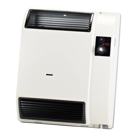
Robur Calorio M User manual

Calorio M
Installation, use and maintenance manual
Fired by natural gas/LPG
Independent direct exchange gas-red convectors with
automatic modulation to heat small and medium-sized
rooms

Revision: F
Code: D-LBR701
This Installation, use and maintenance manual has been drawn up and printed by Robur S.p.A.; whole or partial
reproduction of this Installation, use and maintenance manual is prohibited.
The original is led at Robur S.p.A.
Any use of this Installation, use and maintenance manual other than for personal consultation must be previously
authorised by Robur S.p.A.
The rights of those who have legitimately led the registered trademarks contained within this publication are not
aected.
With the aim of continuously improving the quality of its products, Robur S.p.A. reserves the right to modify the
data and contents of this Installation, use and maintenance manual without prior notice.
DISPOSAL
The appliance and all its accessories must be disposed of separately in accordance with the regulations in force.
Use of theWEEE symbol (Waste Electrical and Electronic Equipment) indicates that this product cannot be disposed of as house-
hold waste. Proper disposal of this product helps to prevent potential negative consequences for the environment and human
health.

Installation, use and maintenance manual – Calorio M 3
I Introduction..........................................................................
p.4
I.1 Recipients................................................................
p.4
II Symbols and denitions.........................................
p.4
II.1 Key to symbols ......................................................
p.4
II.2 Terms and denitions .........................................
p.4
III Warnings...................................................................................
p.4
III.1 General and safety warnings............................
p.4
III.2 Conformity..............................................................
p.5
III.3 Exclusions of liability and warranty ...............
p.6
1 Features and technical data................................
p.7
1.1 Features....................................................................
p.7
1.2 Dimensions.............................................................
p.8
1.3 Electrical wiring diagram...................................
p.9
1.4 Controls....................................................................
p.9
1.5 Technical data......................................................
p.10
2 Transport and positioning..................................
p.10
2.1 Warnings................................................................
p.10
2.2 Handling................................................................
p.10
2.3 Appliance positioning ......................................
p.10
2.4 Minimum clearance distances.......................
p.11
3 Heating engineer...........................................................
p.11
3.1 Warnings................................................................
p.11
3.2 Supplied material...............................................
p.11
3.3 Fuel gas supply....................................................
p.11
3.4 Combustion products exhaust......................
p.13
3.5 Installation procedures ....................................
p.15
4 Electrical installer.........................................................
p.17
4.1 Warnings................................................................
p.17
4.2 Electrical power supply....................................
p.17
4.3 Electrical connection of two appliances....
p.18
5 First start-up.......................................................................
p.19
5.1 Preliminary checks.............................................
p.19
5.2 Checking burner gas pressure.......................
p.20
5.3 Gas changeover ..................................................
p.21
5.4 Access to the advanced setting menu
(INST) ......................................................................
p.22
6 Normal operation.........................................................
p.22
6.1 Warnings................................................................
p.23
6.2 Control panel .......................................................
p.23
6.3 Switch on and o................................................
p.24
6.4 Operating mode selection..............................
p.24
6.5 Access to the USER menu................................
p.25
6.6 Operating faults..................................................
p.26
7 Maintenance.......................................................................
p.27
7.1 Warnings................................................................
p.27
7.2 Cleaning and maintenance.............................
p.27
7.3 Safety devices......................................................
p.27
7.4 Any malfunctions of operation .....................
p.28
8 Appendices...........................................................................
p.30
8.1 Advanced gas-red convector adjustment
and control functions........................................
p.30
8.2 ErP data sheets....................................................
p.32
INDEX OF CONTENTS

Introduction
4
I
I INTRODUCTION
Installation, use and maintenance manual
This Manual is an integral part of the Calorio M
appliance and must be handed to the end user to-
gether with the appliance.
I.1 RECIPIENTS
This Manual is intended for:
▶
End user, for appropriate and safe use of the appliance.
▶
Qualied installer, for correct appliance installation.
▶
Planner, for specic information on the appliance.
II SYMBOLS AND DEFINITIONS
II.1 KEY TO SYMBOLS
DANGER
WARNING
NOTE
PROCEDURE
REFERENCE (to other document)
II.2 TERMS AND DEFINITIONS
Appliance/Unit = equivalent terms, both used to refer to
the independent direct exchange gas-red convector.
TAC = Technical Assistance Centre authorised by Robur.
First start-up = appliance commissioning operation
which may only and exclusively be carried out by a TAC.
III WARNINGS
III.1 GENERAL AND SAFETY WARNINGS
Installer's qualications
Installation must exclusively be performed by a
qualied rm and by skilled personnel, with spe-
cic knowledge on heating, electrical systems and
gas appliances, in compliance with the laws in
force in the Country of installation.
Declaration of conformity
Upon completing installation, the installing rm
shall issue to the owner/client the appliance's
workmanlike conformity declaration, according to
national/local regulations in force and the manu-
facturer's instructions/provisions.
Misuse
The appliance must only be used for the purpos-
es for which it has been designed. Any other use is
deemed hazardous. Incorrect use may aect oper-
ation, duration and safety of the appliance. Adhere
to the manufacturer's instructions.
Use of the appliance by children
The appliance can be used by children over 8 years
old, and by people with reduced physical, senso-
ry or mental capabilities, or lack of experience or
knowledge, only if they are under surveillance or
after they have received instructions regarding
safe use of the appliance and understanding the
dangers inherent in it. Children should not play
with the appliance.
Hazardous situations
Do not start the appliance in hazardous conditions,
such as: gas smell, problems with the electrical/gas
system, parts of the appliance under water or dam-
aged, malfunctioning, disabling or bypassing con-
trol and safety devices.
In case of danger, request intervention by qualied
personnel.
In case of danger, switch o the electrical power
and gas supplies only if this can be done in total
safety.
Do not entrust children, persons with physical,
sensory or mental disabilities or persons with poor
knowledge and experience with use of the appli-
ance.
Gas component tightness
Before performing any operation on gas ducting
components, close the gas valve.
Upon completing any procedure, perform the
tightness test according to regulations in force.
Gas smell

Warnings
Installation, use and maintenance manual – Calorio M 5
III
If you smell gas:
Do not use electrical devices such as telephones,
multimeters or other equipment that may cause
sparks next to the appliance.
Shut o the gas supply by turning the valve o.
Open immediately doors and windows to create a
cross-current of air to ventilate the room.
Switch o the power supply via the external dis-
connect switch in the power supply electrical pan-
el.
Use a telephone away from the appliance to ask for
intervention from qualied personnel.
Poisoning
Ensure the ue gas ducts are tight and compliant
with the regulations in force.
Upon completing any procedure, ensure the tight-
ness of the components.
Moving parts
The appliance contains moving parts.
Do not remove guards during operation, and in
any case prior to disconnecting the power supply.
Burn hazard
The appliance contains very hot parts.
Do not open the appliance and do not touch inter-
nal components before the appliance has cooled
down.
Do not touch the ue gas exhaust before it has
cooled down.
Electrocution hazard
Disconnect the electrical power supply before any
operation on appliance components.
For electrical connections exclusively use compli-
ant components and according to the specica-
tions provided by the manufacturer.
Ensure the appliance cannot be accidentally
switched back on.
Earthing
Electrical safety depends on eective earthing sys-
tem, correctly connected to the appliance and in-
stalled according to the regulations in force.
Air ow
Do not obstruct the fan intake or the warm air
outlet.
Distance from combustible or ammable mate-
rials
Do not deposit ammable materials (paper, dilu-
ents, paints, etc.) near the appliance.
Comply with current regulations.
Aggressive substances in the air
The air of the installation site must be free from ag-
gressive substances.
Switching the appliance o
Disconnecting the power supply while the appli-
ance is running may cause permanent damage to
internal components.
Except in the event of danger, do not disconnect
the power supply to switch o the appliance, but
always and exclusively act through the provided
control device.
In the event of failure
Operations on internal components and repairs
may exclusively be carried out by a TAC, using only
original spare parts.
In the event of failure of the appliance and/or
breakage of any component, do not attempt to
repair and/or restore and immediately contact the
TAC.
Routine maintenance
Proper maintenance assures the eciency and
good operation of the appliance over time.
Maintenance must be performed according to the
manufacturer's instructions (see Chapter 7
p. 27
)
and in compliance with current regulations.
Appliance maintenance and repairs may only be
entrusted to rms legally authorised to work on
gas appliances and systems.
Enter into a maintenance contract with an author-
ised specialised rm for routine maintenance and
for servicing in case of need.
Use only original parts.
Keep the Manual
This Installation, use and maintenance manual
must always accompany the appliance and must
be handed to the new owner or installer in the
event of sale or removal.
III.2 CONFORMITY
EU directives and standards
The Calorio M series gas-red convectors are certied
in accordance with European regulation GAR 426/2016/
EU and meet the essential requirements of the following
Directives:
▶
2016/426/EU "Gas Appliances Regulation" as amend-
ed and added.
▶
2014/30/EC "Electromagnetic Compatibility Directive"
as amended and added.
▶
2014/35/EC "Low Voltage Directive" as amended and
added.

Warnings
6
III
▶
2006/42/EC "Machine Directive" as amended and add-
ed.
▶
2015/1186/EU "Energy labelling of local space heaters
regulation" as amended and added.
▶
2015/1188/EU "Ecodesign requirements for local
space heaters regulation" as amended and added.
Furthermore, they comply with the requirements of the
following standards:
▶
EN 1266 Independent gas-red convection heaters in-
corporating a fan to assist transportation of combus-
tion air and/or ue gases
Other applicable provisions and standards
The design, installation, operation and maintenance of
the systems shall be carried out in compliance with cur-
rent applicable regulations, depending on the Country
and location, and in accordance with the manufacturer's
instructions. In particular, regulations regarding the fol-
lowing shall be complied with:
▶
Gas systems and equipment.
▶
Electrical systems and equipment.
▶
Heating systems.
▶
Environmental protection and combustion products
exhaust.
▶
Fire safety and prevention.
▶
Any other applicable law, standard and regulation.
III.3 EXCLUSIONS OF LIABILITY AND
WARRANTY
Any contractual or extra-contractual liability of the
manufacturer for any damage caused by incorrect
installation and/or improper use and/or failure to
comply with regulations and with the manufactur-
er's directions/instructions shall be disclaimed.
In particular, the warranty on the appliance may be
rendered void by the following conditions:
Incorrect installation.
Misuse.
Failure to comply with the manufacturer's indica-
tions on installation, use and maintenance.
Alteration or modication of the product or any
part thereof.
Extreme operational conditions or however out-
side of the operational ranges set forth by the man-
ufacturer.
Damages caused by external agents such as salts,
chlorine, sulphur or other chemical substances
present in the air of the installation site.
Abnormal actions transmitted to the appliance by
the system or installation (mechanical stresses,
pressure, vibrations, thermal expansion, electrical
surges...).
Accidental damages or due to force majeure.

Features and technical data
Installation, use and maintenance manual – Calorio M 7
1
1 FEATURES AND TECHNICAL DATA
1.1 FEATURES
1.1.1 Operation
The Calorio M gas-red convector is an independent
modulating heating appliance with sealed combustion
chamber and forced draught.
It has been designed to be installed inside the room to be
heated.
It is suitable for operation with natural gas (G20) and LPG
(G30/G31) (gas-red convector belonging to category
II2H3+ according to EN 1266).
The combustion air intake and the exhaust of ue gases
take place outside via two coaxial pipes and are ensured
by the operation of a blower placed in the combustion cir-
cuit. Therefore, the gas-red convector must be installed
on an external perimetral wall or close to it, depending
on the maximum extension of the pipes (see Paragraph
3.4
p.13
).
The operation principle of the Calorio M gas-red convec-
tor is based on a convective motion of room air that pass-
es through the gas-red convector from bottom to top,
is heated and diused into the room through the upper
grille. The recirculation of the room air is facilitated by the
presence of a modulating fan placed in the lower part of
the gas-red convector.
For this reason, do not place clothes, newspa-
pers or any other object that could obstruct the
air outlet directly on the grille. Also make sure
that curtains, backs of chairs or furniture are
not placed at a distance of less than 30 cm from
the gas-red convector.
The operation of the gas-red convector is made very sim-
ple and fully automatic by the control board and control
panel with digital display, tted as standard; in fact, the
only operations required of the user are to start the gas-
red convector, select the required temperature and the
periods of operation.
In heating mode, the heat output and airow rate
modulate according to the room temperature measured
by the temperature probe.
The sealed combustion chamber is the best guarantee of
safety for the environment in which the gas-red convec-
tor is installed: there is no possibility of the products of
combustion leak, nor is the oxygen necessary for combus-
tion taken from the environment. The appliance, once in-
stalled in accordance with the installation standards, does
not require any ventilation openings in the room.
A ame detection device using an ionisation probe in-
terrupts the gas supply in the event of an accidental
shutdown.
The presence of the fan also allows summer operation:
only the fan will work causing a pleasant air ow within
the room.
1.1.2 Mechanical components
▶
Sealed combustion chamber.
▶
High-eciency tubular steel heat exchanger.
▶
Centrifugal fan with modulating operation.
▶
Ø 49/35 mm coaxial combustion air intake and ue
gas exhaust pipes.
▶
External windproof terminal in aluminium alloy (pat-
ented).
▶
Casing in epoxy powder-coated sheet metal.
▶
Support bracket for wall mounting.
1.1.3 Control and safety devices
▶
Electronic management board providing the follow-
ing functions:
burner ignition
ame monitoring and modulation
blower management and control
fan speed control
heat exchanger temperature probe control
▶
Manual reset limit thermostat.
▶
Prelimit temperature probe.
▶
Room air temperature probe.
▶
Flue gas exhaust blower.
▶
Gas solenoid valve.
▶
User interface board with backlit digital display.

Features and technical data
8
1
1.2 DIMENSIONS
Figure1.1Dimensions
208
≥100
≥50
30
Ø 35
Ø 49
≥100 ≥100
553
276 276
354
715

Features and technical data
Installation, use and maintenance manual – Calorio M 9
1
1.3 ELECTRICAL WIRING DIAGRAM
Figure1.2Electrical wiring diagram
SCH Electronic board
EV Gas valve
L Line
N Neutral
M1 Manual reset limit thermostat
M9 2 A fuse
RP7 Ignition electrodes
RP8 Detection electrode
S Combustion air blower
V Room fan
TP Pre-limit temperature probe
TA Room temperature probe
X Stocko connectors
CC External request connection
SI Interface board
4EV
EV1 EV2
3
2
1
SV
SI
M1
TA
TP
CC
RP7
RP8
L
220-240 V / 50 Hz
N
M9
F1
SCH X1
X2
X3
X4
X5
1
2
3
4
5
4
6
7
3
2
1
7
6
5
4
3
2
1
6
7
8
9
10
11
12
5
4
3
2
1
4
3
2
1
3.15AF
250V
-
+
+
-
1.4 CONTROLS
1.4.1 Control device
The appliance operation is controlled by the supplied
control panel.
For further information please refer to Paragraph
6.2
p.23
.

Transport and positioning
10
2
1.5 TECHNICAL DATA
Table1.1Technical data
42M 52M
Heating mode
Heat input nominal (1013 mbar - 15 °C) (1) kW 3,6 5,2
minimum (1) kW 2,5 3,6
Heat output nominal kW 3,3 4,7
minimum kW 2,3 3,2
Eciency nominal heat input % 90,0
Electrical specications
Power supply
voltage V 230
type - single-phase
frequency Hz 50
Electrical power absorption nominal kW 0,05 0,09
Installation data
Gas consumption
G20 natural gas (nominal) m³/h 0,38 0,55
G20 natural gas (min) m³/h 0,27 0,38
G30 (nominal) kg/h 0,29 0,41
G30 (min) kg/h 0,20 0,28
G31 (nominal) kg/h 0,30 0,40
G31 (min) kg/h 0,20 0,28
Gas connection type - M
thread “ 1/2
Flue gas exhaust
diameter (Ø) mm 50
type of installation - C13, C33, C63
residual head Pa 30 35
maximum equivalent length of coaxial exhaust duct m 1
sound power Lw(max) dB(A) 50,5 56,5
sound power Lw(min) dB(A) 47,5 52,5
sound pressure Lpat 5 metres (max) dB(A) 31,5 37,5
sound pressure Lpat 5 metres (min) dB(A) 28,5 33,5
Dimensions
width mm 553
height mm 715
depth mm 208
Weight in operation kg 25 26
(1) Relative to NCV (net caloric value).
2 TRANSPORT AND POSITIONING
2.1 WARNINGS
Damage from transport or installation
The manufacturer shall not be liable for any dam-
age during appliance transport and installation.
On-site inspection
Upon arrival at the site, ensure there is no transport
damage on packing.
After removing the packing materials, ensure the
appliance is intact and complete.
Packing
Only remove the packing after placing the appli-
ance on site.
Do not leave parts of the packing within the reach
of children (plastic, polystyrene, nails...) since they
are potentially dangerous.
Weight
The lifting equipment must be suitable for the load.
Lift up the unit and secure it to its support bracket
(Paragraph 3.5.1
p.15
).
2.2 HANDLING
2.2.1 Handling and lifting
▶
Always handle the appliance in its packing, as deliv-
ered by the factory.
▶
Comply with safety regulations at the installation site.
2.3 APPLIANCE POSITIONING
The appliance must be installed in the room to be heated.

Heating engineer
Installation, use and maintenance manual – Calorio M 11
3
2.3.1 Where to install the appliance
▶
The gas-red convector must be installed on or near
an external perimeter wall, respecting the distances
indicated in Figure 1.1
p.8
.
▶
Avoid placement on walls or combustible materials
without a suitable heat shield.
▶
Do not install the gas-red convector over electrical
boxes/switches or distribution cabinets that require
periodic inspection.
Installation must not be made on walls with poor
strength that do not guarantee adequate resist-
ance to the stresses produced by the appliance.
The manufacturer assumes no responsibility if the
appliance is installed on surfaces or walls that are
not suitable to support its weight.
The appliance's ue gas exhaust must not be im-
mediately close to openings or air intakes of build-
ings, and must comply with safety and environ-
mental regulations.
The ue gas exhaust terminal is accident-pre-
venting and requires no protection.
2.4 MINIMUM CLEARANCE DISTANCES
2.4.1 Distances from combustible or ammable
materials
▶
Keep the appliance away from combustible or am-
mable materials or components, in compliance with
applicable regulations.
2.4.2 Clearances around the appliance
The minimum clearance distances are required for
safety, operation and maintenance.
▶
The minimum recommended distance from the gas-
red convector to the oor is 5 cm (Figure 1.1
p. 8
)
and possibly not more than 35 cm, as higher heights
would result in uneven heat distribution in the heated
room.
▶
Keep a minimum clearance of 10 cm from the sides of
the gas-red convector to any obstacles to allow for
removal and retting of the casing.
▶
If a shelf is to be installed above the gas-red convec-
tor, leave a minimum clearance of 10 cm. No cover of
any type may be installed over the appliance.
3 HEATING ENGINEER
3.1 WARNINGS
3.1.1 General warnings
Read the warnings in Chapter III.1
p. 4
, pro-
viding important information on regulations and
on safety.
Compliance with installation standards
Installation must comply with applicable regula-
tions in force, based on the installation Country
and site, in matters of safety, design, implementa-
tion and maintenance of:
heating systems
gas systems
ue gas exhaust
Installation must also comply with the manufactur-
er's provisions.
3.2 SUPPLIED MATERIAL
▶
Installation jig in cardboard.
▶
Wall support bracket.
▶
Air duct Ø 49 mm, length 500 mm.
▶
Flue gas duct Ø 35 mm, length 500 mm.
▶
External ue gas terminal in aluminium alloy.
▶
Round gasket for combustion air.
▶
Screws and wall plugs.
▶
Documentation.
3.3 FUEL GAS SUPPLY
3.3.1 Gas connection
▶
1/2" M
on the right, at the bottom (detail A in Figure 3.1
p.12
).
▶
Install an anti-vibration connection between the ap-
pliance and the gas piping.

Heating engineer
12
3
Figure3.1Gas supply position
A Gas connection
A
The connection to the gas mains must be made
using a rigid copper or steel pipe and ttings; alter-
natively, a exible stainless steel pipe conforming
to the regulations in force may also be used.
The connection to the gas pipe must be properly
sealed to ensure tightness using a sealant that
complies with EN 751-1 and EN 751-2. The connec-
tion must be made in such a way that no strain is
produced in the pipe or gas-red convector com-
ponents.
3.3.2 Mandatory shut-o valve
▶
Provide a gas shut-o valve (manual) on the gas supply
line, next to the appliance, to isolate it when required.
▶
Provide a three-piece pipe union.
▶
Perform connection in compliance with applicable
regulations.
3.3.3 Gas pipes sizing
The gas pipes must not cause excessive pressure drops
and, consequently, insucient gas pressure for the
appliance.
3.3.4 Supply gas pressure
This appliance is equipped for a maximum gas
supply pressure of 50 mbar.
The appliance's gas supply pressure, both static and dy-
namic, must comply with Table 3.1
p.12
, with tolerance
± 15%.
Non compliant gas pressure (Table 3.1
p. 12
)
may damage the appliance and be hazardous.
Table3.1Network gas pressure
Gas supply pressure [mbar]
Product category Countries of destination G20 G30 G31 G30 G31
II2H3B/P
AL, BG, CH, CZ, DK, EE, FI, HR, LT, LV, MK, RO, SE, SI,
SK, TR 20 30 30
AT, CH 20 50 50
II2H3P BG, EE, HR, LT, SI, SK 20 37
II2H3+ CZ, ES, GB, GR, IE, IT, PT, SK 20 28-30 37
I3+ FR, BE 28-30 37
II2H3B/P HU 25 30 30
II2HS3B/P HU 25 30 30
II2E3B/P
LU 20 50
PL 20 37 37
DE 20 50 50
I2H LV 20
I3P NO 30
I3B/P MT, CY 30 30
I3B 30
The appliance gas supply pressure, both static and dynamic, must comply with the values in the Table, with a tolerance of ± 15%.
3.3.5 Vertical pipes and condensate
▶
Vertical gas pipes must be tted with siphon and dis-
charge of the condensate that may form inside the
pipe.
▶
If needed, insulate the piping.
3.3.6 LPG pressure reducers
With LPG the following must be installed:
▶
A rst stage pressure reducer, close to the liquid gas
tank.
▶
A second stage pressure reducer, close to the appli-
ance.
Pressure reducers must always be installed outside
the building.

Heating engineer
Installation, use and maintenance manual – Calorio M 13
3
3.4 COMBUSTION PRODUCTS EXHAUST
Compliance with standards
The appliance is approved for connection to a
combustion products exhaust duct for the types
shown in Table 1.1
p.10
.
3.4.1 Flue gas exhaust and combustion air
intake connection
▶
Ø 50 mm on the rear (Figure 1.1
p.8
)
3.4.2 Installation types
The ue gas exhaust/combustion air intake of the
Calorio M gas-red convectors can be realised in one of
the following ways:
▶
With coaxial pipes with outlet on the installation
wall (maximum pipe length: 1 metre) (see Figure
3.2
p.13
).
▶
With coaxial pipes with 90° outlet (max pipe length: 1
metre) (see Figure 3.3
p.14
). In this case, it is neces-
sary to use the 90° casing for coaxial pipes, available as
OCFF004 optional.
▶
With separate pipes (see Figure 3.4
p. 14
) . In this
case, it is necessary to use the separate exhaust casing
available as OCFF002 optional.
Warnings
The installation of pipes with a vertical downward
outlet is prohibited (leads to recirculation of ue
gas with lock-out of the appliance).
It is forbidden to install coaxial pipes with a vertical
outlet upwards (due to rain, water, objects inltra-
tion with consequent lock out of the appliance).
Figure3.2Installation with straight coaxial pipes
A Air pipe Ø 49 mm
B Flue gas pipe Ø 35 mm
C Adhesive gasket
D Support bracket
E Wall terminal Ø 35 mm
A
B
C
D
E
IM14044

Heating engineer
14
3
Figure3.3Installation with coaxial pipes with 90° outlet
A Air pipe Ø 49 mm
B Flue gas pipe Ø 35 mm
C Adhesive gasket
D Support bracket
E Wall terminal Ø 35 mm
F 90° casing for coaxial exhaust
A
B
C
D
E
F
Figure3.4Installation with wall separate ducts
A Air/ue gas pipe Ø 35 mm
B Elbow 90° M/F Ø 35 mm
C Adhesive gasket
D Support bracket
E Wall terminal Ø 35 mm
F 90° casing for separate exhaust
G Condensate discharge Ø 35 mm
D
A
BAA
AA
A
B
B
B
E
F
C
G
For further information on the installation of the
ue gas exhaust/air intake duct, please refer to the
installation guide for the ue gas exhaust/air intake
ducts D-GPP001, available on the Robur website.
3.4.2.1 Installation with separate ducts
If the appliance is installed with separate pipes, suitable
pipes and components, available as optional, must be
used.
At the design stage, it must be veried that the sum of the
pressure drop of all components used does not exceed
the value of the available residual head (Table 3.2
p.14
).
Table3.2Separate exhaust pressure drop table
Description Code 42M 52M
residual head Pa 30 35
Air pipe internal Ø 33 mm OPRL000 Pa/m 2,0 3,0
Horizontal ue gas pipe internal
Ø 33 mm OPRL000 Pa/m 2,0 3,6
Vertical ue gas pipe internal Ø
33 mm OPRL000 Pa/m 0,7 2,0
90° elbow on air pipe OCRV000 Pa 2,0 3,0

Heating engineer
Installation, use and maintenance manual – Calorio M 15
3
Description Code 42M 52M
90° elbow on ue gas pipe OCRV000 Pa 1,8 3,6
Casing complete with internal
elbow for ue gas exhaust OCFF002 Pa 2,5 5,0
Casing without internal elbow for
ue gas exhaust OCFF002 Pa 1,8 3,0
Roof terminal Ø 35 mm OTRM002 Pa 0,0 0,0
Wall terminal JTRM000B Pa 0,0 0,0
Condensate discharge Ø 35 mm OSCR003 Pa 0,0 0,0
If the ue gas pipe is longer than 1,5 metres, a condensate
drain (available as OSCR003 optional) must be installed
on the pipe as close as possible to the appliance. To limit
the formation of condensate, it is in any case advisable to
insulate the ue gas pipe with a material resistant to high
temperatures.
Due to the high temperatures that the ue gas pipe
can reach, it is still advisable to insulate it from the
wall and from potential contact with things and
people, for example by using rock wool or glass
wool.
The ue gas exhaust terminal, if used only for ue
gas exhaust, must also be protected against acci-
dental contact with people and things, due to the
high temperatures it can reach.
3.5 INSTALLATION PROCEDURES
In accordance with the installation project, prepare the
gas and electrical supply lines, as well as the holes for the
ue gas outlet and combustion air intake.
3.5.1 Install the gas-red convector on the wall
1. Check the packaging for visible signs of damage, oth-
erwise, notify the carrier immediately.
2. Remove the gas-red convector from its packaging
by rst removing the air intake and ue gas exhaust
pipes. Do not damage or discard the cardboard jig
with the drilling template required for installing the
gas-red convector.
3. Fix the jig to the wall where the gas-red convector is
to be installed, making sure it is perpendicular to the
oor.
4. Drill the hole (Ø 50 mm) to house the larger pipe and
holes A (Figure 3.6
p. 16
) to x the support brack-
et (drill 6 mm holes to insert the provided wall plugs).
The Ø 50 mm hole for the duct can be made with a
suitable core drill or by means of a succession of small-
er holes made with a simple drill on the perimeter to
be removed.
5. Adjust the length of the pipes (air intake and ue gas
exhaust) to the actual thickness of the wall by cutting
o the excess length: to determine the exact length
see diagram Figure 3.5
p.15
.
The coaxial duct must in any case not be less than
20 cm in length (ue gas pipe 200 + 33 mm, air in-
take pipe 200 + 2 mm).
In the Ø 49 pipe, do not cut the side with the
edging, which will later be used to secure the pipe.
In the Ø 35 pipe, do not cut o the side with a skirt-
ed end that will be used to t the pipe to the gas-
red convector.
6. Remove the jig from the wall.
Figure3.5Indications for cutting air/ue gas pipes

Heating engineer
16
3
Figure3.6Support bracket positioning and holes drilling
A Bracket xing holes
B Support bracket
C Adhesive gasket
D Air pipe
B
D
C
A
A
7. Position the support bracket and the air intake pipe Ø
49, making sure that the pipe edge perfectly enters the
matching hole in the bracket (see Figure 3.6
p.16
).
8. Fix the support bracket with the screws and position
the round adhesive gasket around the hole in the
bracket (see Figure 3.6
p.16
).
9. Position the self-adhesive foam gasket strip on the
support frame (at the rear of the gas-red convector)
as shown in Figure 3.7
p.16
. Try to avoid reposition-
ing which could be dicult.
10.Fit the end of the ue gas exhaust pipe (Ø 35 mm)
onto the gas-red convector outlet socket (Figure
3.8
p.16
).
11.Mount the gas-red convector to the wall by resting
slot C on the lower edge of the frame on the support
bracket, as shown in Figure 3.9
p.16
.
Figure3.7Positioning the gasket
1 Self-adhesive gasket
1
Figure3.8Positioning the ue gas exhaust pipe
1 Flue gas pipe Ø 35 mm
1
Figure3.9Attachment to the support bracket
A Bracket end for hooking to the gas-red convector
B Lateral eyelets for xing to the bracket
C Lower eyelet for xing to the bracket
D Holes for securing the gas-red convector to the wall
A
A
B
B
DC
D
12.Fit the slots B to the ends A of the support bracket
and push the gas-red convector towards the wall so

Electrical installer
Installation, use and maintenance manual – Calorio M 17
4
that it seats against the support bracket (see Figure
3.10
p.17
).
13.Secure the gas-red convector to the support bracket
by means of the two side screws as shown in Figure
3.10
p.17
.
Figure3.10Attachment detail
A Bracket end for hooking to the gas-red convector
B Lateral eyelets for xing to the bracket
A
B
3.5.2 Install the windproof terminal
1. When the appliance is installed, place the aluminium
windproof terminal to the outdoor wall so that it en-
gages with the end of the ue gas pipe and mark the
position of the three holes for the expansion plugs
(see Figure 3.11
p. 17
). The terminal must be tted
with the ue outlet grille arranged vertically.
2. Remove the terminal and drill the xing holes (6 mm Ø
for the supplied wall plugs).
3. Reassemble the terminal and secure it with the screws
using the relevant plugs (see Figure 3.11
p.17
).
Figure3.11Windproof terminal xing
4 ELECTRICAL INSTALLER
4.1 WARNINGS
General warnings
Read the warnings in Chapter III
p. 4
, provid-
ing important information on regulations and on
safety.
Compliance with installation standards
Installation must comply with applicable regula-
tions in force, based on the installation Country
and site, in matters of safety, design, implementa-
tion and maintenance of electrical systems.
Installation must also comply with the manufactur-
er's provisions.
Live components
After placing the appliance in the nal position,
and prior to making electrical connections, ensure
not to work on live components.
Earthing
The appliance must be connected to an eective
earthing system, installed in compliance with reg-
ulations in force.
It is forbidden to use gas pipes as earthing.
Cable segregation
Keep power cables physically separate from signal
ones.
Do not use the power supply switch to turn the
appliance on/o
Never use the power supply switch to turn the ap-
pliance on and o, since it may be damaged in the
long run (occasional blackouts are tolerated).
To turn the appliance on and o, exclusively use
the suitably provided control device.
4.2 ELECTRICAL POWER SUPPLY
Provide (by the installer) a protected single-phase line
(230 V 1-N 50 Hz).
How to connect the power supply
1. To connect the gas-red convector to the mains power
supply, simply wire the supplied 3-pole plug as shown
in Figure 4.1
p.18
using 3x0,75 mm² cable.
2. Insert the previously wired 3-pole plug into the socket
located on the lower right of the gas-red convector
frame.

Electrical installer
18
4
Figure4.1Three-pole plug wiring
1 Blue cable
2 Yellow/green cable
3 Brown or black cable
4 Cable type 3x0,75 mm²
1
2
3
4
If required, the electrical socket on the frame can
be rotated 180° to allow the electrical cable to exit
to the left instead of the right.
4.3 ELECTRICAL CONNECTION OFTWO APPLIANCES
Figure4.2Wiring diagram for 2 appliances
CC External request connection for
single appliance
RL Relay
CS External centralised request
IP Main switch
L Phase
N Neutral
CC
L
IP
N
RL
CC CS
4
3
3
4

First start-up
Installation, use and maintenance manual – Calorio M 19
5
Figure4.3Wiring diagram for 2 appliances
CC External request connection for
single appliance
RL Relay
CS External centralised request
IP Main switch
L Phase
N Neutral
RL
IP
N
L
CC CC
RL
CS
4
33
4
5 FIRST START-UP
First start-up entails checking/setting up the com-
bustion parameters and may exclusively be carried
out by a Robur TAC. NEITHER the user NOR the in-
stallation technician is authorised to perform such
operations, under penalty of voiding the warranty.
The installer is obliged to carry out preliminary
checks described in Paragraph 5.1
p.19
.
5.1 PRELIMINARY CHECKS
Paragraph dedicated to the installer.
5.1.1 Preliminary checks for rst start-up
Upon completing installation, before contacting the TAC
the installer must check:
▶
Electrical and gas systems suitable for the required ca-
pacities and equipped with all safety and control de-
vices required by the regulations in force.
▶
Absence of leaks in the gas system.
▶
Type of gas for which the appliance is designed (natu-
ral gas, LPG or other gas).
▶
Supply gas pressure complying with the values of
Table 3.1
p.12
, with max tolerance ±15%.
▶
Correct operation of the ue exhaust duct.
▶
Combustion air intake and ue gas exhaust correctly
carried out according to the regulations in force.
▶
Power supply mains complying with the appliance's
rating plate data.
▶
Appliance correctly installed, according to the manu-
facturer's provisions.
▶
System installed in a workmanlike manner, according
to national and local regulations.
5.1.2 Abnormal or hazardous installation
situations
Should any abnormal or hazardous installation situations
be found, the TAC shall not perform rst start-up and the
appliance shall not be commissioned.
These situations may be:
▶
Failed compliance with minimum clearances.
▶
Insucient distance from combustible materials.
▶
Conditions that do not warrant access and mainte-
nance in safety.
▶
Appliance defects or faults caused during transport or
installation.
▶
Gas smell.
▶
Non-compliant mains gas pressure.
▶
Non-compliant ue gas exhaust.
▶
All situations that may involve operation abnormali-
ties or are potentially hazardous.
5.1.3 Non-compliant system and corrective
actions
Should theTAC nd any non conformities, the user/install-
er is bound to perform any corrective procedures required

First start-up
20
5
by the TAC.
After performing the remedial actions (the installer's re-
sponsibility), if the TAC deems that safety and conformity
conditions are in place, rst start-up may be eected.
5.2 CHECKING BURNER GAS PRESSURE
Paragraph reserved exclusively to TACs.
The gas supply circuit is equipped with a gas so-
lenoid valve with double safety shutter and pres-
sure regulator to control the gas ow. All models
are factory-set to operate with natural gas and can
be converted to LPG (see Paragraph 5.3
p. 21
).
Each gas-red convector is calibrated during fac-
tory testing for operation with natural gas. After
installation, check that the gas pressure at the
burner complies with indications in Paragraph
5.3.1
p.21
.
5.2.1 Natural gas supply
Figure 5.1
p.20
1. Remove the casing.
2. Connect a pressure gauge to the pressure intake A, af-
ter removing its sealing screw.
3. To adjust the gas pressure, the gas-red convector
must be switched o, then access the "advanced set-
tings menu" and the submenu "transparent control
parameters" as described in the relevant Paragraph
5.4.2
p.22
.
4. Activate the function "valve calibration" by turning
the knob until the parameter P002 is displayed; then,
using the knob (press – rotate – press), change the
parameter value to 15: previous valve settings will be
deleted.
5. Wait until the value 20 appears on the display (the gas-
red convector will turn on).
6. Turn the knob to display the parameter P03 "gas pres-
sure calibration at maximum power".
7. Press the knob and increase the displayed value by 1
to 5 points at a time (this operation may be repeated
several times), until the pressure gauge reads 8 mbar;
then proceed in small increments (+1) up to the re-
quired maximum pressure value (Table 5.1
p.20
).
Be careful not exceed the required gas pressure! If
this happens, you must repeat the calibration pro-
cedure (starting from step 4).
8. Turn the knob to display the parameter P04 "gas pres-
sure calibration at minimum power".
9. Press the knob and change the displayed value, start-
ing with minimal decrements (-1); press the knob
to conrm and wait for the pressure gauge read-
ing. Proceed in this way (with minimal decrements)
down to the required minimum pressure value (Table
5.1
p.20
).
10.Save the new parameter settings by turning the knob
to display parameter P002 and then pressing it to
conrm.
11.Deactivate the "valve calibration" function by turning
the knob and pressing it to set parameter P002 to "0":
the gas-red convector will switch o.
After the adjustment, stop and start the appliance
and check that burner pressure has stabilised. If
necessary perform the adjustment again.
12.Disconnect the pressure gauge and ret the sealing
screw.
13.Replace the casing.
Figure5.1Pressure intake
A Pressure intake
A
Table5.1Burner gas pressure
42M 52M
Installation data
Burner gas
pressure
Nominal
heat input
G20 mbar 10,5 9,0
G30 mbar 28,8 28,0
G31 mbar 36,7 35,5
Minimal
heat input
G20 mbar 6,0 5,0
G30 mbar 14,0 14,7
G31 mbar 18,0 19,7
5.2.2 LPG supply
For LPG supply, the gas-red convector must be converted
from natural gas to LPG by using the supplied gas change
kit and following the instructions in Paragraph 5.3
p.21
.
When operating with LPG gas, the maximum operating
pressure depends only on the network pressure, which
must be as indicated in Table 3.1
p.12
.
The reduction of the pressure in the network is
possible following the instructions in Paragraph
3.3.6
p.12
.
Other manuals for Calorio M
1
This manual suits for next models
1
Table of contents
Other Robur Heater manuals

Robur
Robur 5001 User manual

Robur
Robur Next-R User manual

Robur
Robur Supercromo D-LBR167 Quick start guide

Robur
Robur TS2000 Series User manual

Robur
Robur Next-R Service manual

Robur
Robur G 30 Service manual

Robur
Robur TS 2000 User manual

Robur
Robur AY00-119 Series User manual

Robur
Robur Heaters Line F2 C Series Service manual

Robur
Robur Supercromo User manual