Speck pumps S90 User manual

OWNER’S MANUAL
Swimming Pool Pump
READ THIS MANUAL CAREFULLY
BEFORE USING THE SPECK PUMP
SECTION 1 IMPORTANT SAFETY INSTRUCTIONS
NOTE: All wiring should be done by a qualified electrician in accordance with the National Electrical Code and all Local Codes.
All pumps are water tested on a test stand to ensure that they meet specification.
SECTION 2 WINTERIZING
In areas subject to freezing winter temperatures,
protect by removing drain plugs. Do not replace plug.
Store plug in strainer basket for winter.
An alternative is to remove the pump and motor from
plumbing and store indoors in a warm and dry location.
NOTE: Before installation, inspect all equipment, plumbing and wiring for damage that may have occurred during shipment.
The shipping container has been specifically designed to prevent damage, however, any indications of damage should be
carefully noted on the delivery ticket and a claim needs to be filed with the carrier.
WARNING - To reduce the risk of injury, do not
permit children to use this product unless they are
closely supervised at all times.
WARNING - Risk of Electric Shock. Connect only
to a branch circuit protected by a ground-fault
circuit interrupter (GFCI). Contact a qualified
electrician if you cannot verify that the circuit is
protected be a GFCI.
WARNING - To reduce the risk of electric shock,
replace any damaged cord immediately.
CAUTION - This pump is for use with
permanently-installed pools and may also be used
with hot tubs and spas if so marked. Do not use
with storable pools. A permanently-installed pool is
constructed in or on the ground or in a building
such that it cannot be readily disassembled for
storage. A storable pool is constructed so that it is
capable of being readily disassembled for storage
and reassembled to its original integrity.
Do not install within an outer enclosure or beneath
the skirt of a hot tub or spa.
The unit must be connected only to a supply circuit
that is protected by a ground-fault circuit-interrupter
(GFCI). Such a GFCI should be provided by the
installer and should be tested on a routine basis. To
test the GFCI, push the test button. The GFCI
should interrupt power. Push the reset button.
Power should be restored. If the GFCI fails to
operate in this manner, the GFCI is defective. If the
GFCI interrupts power to the pump without the test
button being pushed, a ground current is flowing,
indicating the possibility of an electric shock. Do
not use this pump. Disconnect the pump and have
the problem corrected by a qualified service
representative before using.
When installing and using this electrical equipment,
basic safety precautions should always be followed,
including the following:
9.
TO REDUCE RISK OF ELECTRICAL
SHOCK, A copper bonding connector (8 AWG) is
provided for bonding the motor to all metal parts of
the swimming pool, spa, or hot tub structure and to
all electrical equipment, metal conduit, and metal
piping within 5 feet of the inside walls of a
swimming pool, spa, or hot tub, when the motor is
installed within 5 feet of the inside walls of the
swimming pool, spa, or hot tub.
NOTE: To installer and/or operator of the Speck
Swimming Pool Pump; the manufacturer’s waranty
will be voided if the pump is improperly installed
and/or operated.
grounded.
Locate pump as close to the pool as practical.
Consult local codes for minimum dis t ance between
pool and pump.
The piping should be as direct and free from turns or
bends as possible, as elbows and other fittings greatl y
increase friction losses.
Place pump on a solid foundation which provides a
rigid and vibration-free support so that it is readily
accessible for service and maintenance.
Pro t ec t t he pump agains t f looding and excess
moisture, and prevent foreign objec t s from clogging
air circulation around moto r .
DO N O T store or use gasoline or other flammable
vapors or liquids in the vicinity of this pump . DO N O T
store pool chemicals near the pump.
DO N O T remove any safety alert labels such as
D ANG E R , WARN I N G , o r C A U TI ON . Keep safet y
label s in good c ondi t ion and r epla c e m i ss ing o r
damaged labels.
SECTIO N 3 EQUIPMEN T OPER A TIO N A N D MAINTE N ANC E
SECTION 4 MAINTE N ANC E
2/1 L OC A TION
2/2 INS T ALL A TION
1 .
2 .
3 .
4 .
5 .
6 .
1 .
2 .
3 .
4 .
The pump requires little or no service other than
reasonable care and periodic cleaning of the strainer
basket. The seal on the pump is a mechanical seal.
The seal may come loose during the course of time,
depending on the running time and water qualit y . If
water continually leaks out, a new mechanical seal
should be fitted.
To replace the mechanical seal, remove the eight bolts
holding the casing to the seal housing. Slide the motor
p art including the seal-housing out. Remove impeller
by turning it counter-clockwise when facing it, while
holding motor shaft with a 7/16” wrench or screw driver
at rear end of motor. Slide seal from impeller shaft. To
re-assemble, reverse the process. Note: Make sure
both parts of the mechanical seal (ceramic and spring
portion) are clean. Gently wipe polished faces with
soft and dry cotton cloth. Surfaces can easily be
damaged by dirt and scratching. Only water should be
used as a lubricant to mount both parts of the mechani-
seal.
RE V . 0411 - Model S90 2999999927
BONDING: As required by National Electrical Code
Article 680-22, the pump motor must be electrically
bonded to the pool structure (reinforced bars, etc.) by
a solid copper conductor not smaller than #8 A WG via
the external copper bonding lug on the pump moto r .
G R OUNDING : Permanently ground the pum p
motor using a conductor of appropriate size. Connect
to the #10 green headed ground screw provided
inside the motor terminal box.
N
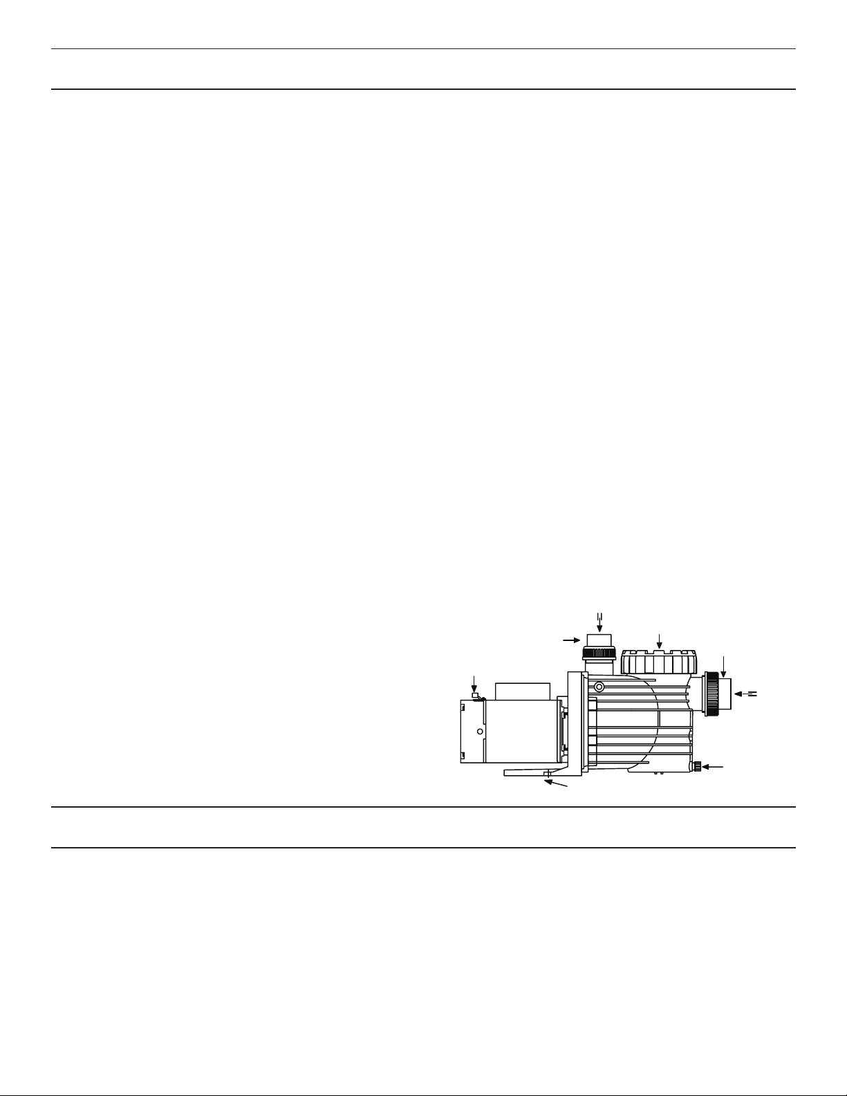
Figure 1.0
O TE: Do not connect to electric power supply until
unit is permanently
When connecting pipework to pump with threaded ports
it is recommended that thread seal tape be used. If
the suction pipe is not sealed correctly, the pump will
not prime properly and will pump small volumes of
water or none at all.
When installing the pump, care should be taken to see
the suction line is below water level to a point to a
point immediately beneath the pump to ensure quick
priming via a flooded suction line. The height between
the pump and water level should not be more than
5 feet.
Suction and discharge line should be independently
supported at a point near the pump to avoid strains
being placed on the pump.
It is advisable to install a gate valve in both the suction
and discharge line in the event that the pump must be
removed for servicing.
5 .
Before starting the pump for the first time, remove the
Fill strainer tank with water until it is level with the
suction inlet. Replace lid, making sure the o-ring is not
damaged. Screw down, hand tight.
6 .
When installing and using the motor, basic safety
precautions should always be followed. The wiring of
motor should be done by a licensed electrician in accor -
dance with local codes. Be certain that the motor frame
is grounded. Motor name plate has voltage, phase,
ampere draw and other motor information as well as
wiring connection instructions.
see-through lid. (Turn lid counterclockwise to remove.)
strainer basket cover
discharge port
to filter or pool
bonding lug
pump may be bolted to level
foundation or mounting bracket
suction port
from pool or
vacuum filters
drain plug
disconnect
unions disconnect unions

grounded.
Locate pump as close to the pool as practical.
Consult local codes for minimum dis t ance between
pool and pump.
The piping should be as direct and free from turns or
bends as possible, as elbows and other fittings greatl y
increase friction losses.
Place pump on a solid foundation which provides a
rigid and vibration-free support so that it is readily
accessible for service and maintenance.
Pro t ec t t he pump agains t f looding and excess
moisture, and prevent foreign objec t s from clogging
air circulation around moto r .
DO N O T store or use gasoline or other flammable
vapors or liquids in the vicinity of this pump . DO N O T
store pool chemicals near the pump.
DO N O T remove any safety alert labels such as
D ANG E R , WARN I N G , o r C A U TI ON . Keep safet y
label s in good c ondi t ion and r epla c e m i ss ing o r
damaged labels.
SECTIO N 3 EQUIPMEN T OPER A TIO N A N D MAINTE N ANC E
SECTION 4 MAINTE N ANC E
2/1 L OC A TION
2/2 INS T ALL A TION
1 .
2 .
3 .
4 .
5 .
6 .
1 .
2 .
3 .
4 .
The pump requires little or no service other than
reasonable care and periodic cleaning of the strainer
basket. The seal on the pump is a mechanical seal.
The seal may come loose during the course of time,
depending on the running time and water qualit y . If
water continually leaks out, a new mechanical seal
should be fitted.
To replace the mechanical seal, remove the eight bolts
holding the casing to the seal housing. Slide the motor
p art including the seal-housing out. Remove impeller
by turning it counter-clockwise when facing it, while
holding motor shaft with a 7/16” wrench or screw driver
at rear end of motor. Slide seal from impeller shaft. To
re-assemble, reverse the process. Note: Make sure
both parts of the mechanical seal (ceramic and spring
portion) are clean. Gently wipe polished faces with
soft and dry cotton cloth. Surfaces can easily be
damaged by dirt and scratching. Only water should be
used as a lubricant to mount both parts of the mechani-
seal.
RE V . 0411 - Model S90 2999999927
BONDING: As required by National Electrical Code
Article 680-22, the pump motor must be electrically
bonded to the pool structure (reinforced bars, etc.) by
a solid copper conductor not smaller than #8 A WG via
the external copper bonding lug on the pump moto r .
G R OUNDING : Permanently ground the pum p
motor using a conductor of appropriate size. Connect
to the #10 green headed ground screw provided
inside the motor terminal box.
N
Figure 1.0
O TE: Do not connect to electric power supply until
unit is permanently
When connecting pipework to pump with threaded ports
it is recommended that thread seal tape be used. If
the suction pipe is not sealed correctly, the pump will
not prime properly and will pump small volumes of
water or none at all.
When installing the pump, care should be taken to see
the suction line is below water level to a point to a
point immediately beneath the pump to ensure quick
priming via a flooded suction line. The height between
the pump and water level should not be more than
5 feet.
Suction and discharge line should be independently
supported at a point near the pump to avoid strains
being placed on the pump.
It is advisable to install a gate valve in both the suction
and discharge line in the event that the pump must be
removed for servicing.
5 .
Before starting the pump for the first time, remove the
Fill strainer tank with water until it is level with the
suction inlet. Replace lid, making sure the o-ring is not
damaged. Screw down, hand tight.
6 .
When installing and using the motor, basic safety
precautions should always be followed. The wiring of
motor should be done by a licensed electrician in accor -
dance with local codes. Be certain that the motor frame
is grounded. Motor name plate has voltage, phase,
ampere draw and other motor information as well as
wiring connection instructions.
see-through lid. (Turn lid counterclockwise to remove.)
strainer basket cover
discharge port
to filter or pool
bonding lug
pump may be bolted to level
foundation or mounting bracket
suction port
from pool or
vacuum filters
drain plug
disconnect
unions disconnect unions
Make sure see-through lid and o-ring are
clean and properly positioned. Tighten
see-through lid (hand tight). Tighten all
pipes and fittings on suction side of pump.
Be sure water in pool is high enough to
flow through skimmer.
Make sure strainer tank is full of water.
Open all valves in system. Clean skimmer
and strainer tank. Open pump and check
for clogging of impeller.
Check voltage at motor. If low, pump will
not come up to speed.
Check that all power switches are on. Be
sure fuse or circuit breaker is properly set.
Time set properly? Check motor wiring at
terminals.
With power off, turn shaft. It should spin
freely. If not, disassemble and repair.
Back wash filter when filter pressure is
high, or clean cartridges.
Clean skimmer and pump strainer baskets.
See problem 1.
See problem 1.
Noise when shaft is turned up by hand.
Motor is hot in bearing area when running.
Replace bearings.
Increase size of electrical wire. Be sure
motor is operating on correct voltage.
Shield motor from sun’s rays.
Do not tighten cover or enclose motor.
a. Suction air leak.
b. No water in pump.
c. Closed valves or blocked lines.
d. Low voltage to motor.
a. No power to motor.
b. Pump jammed.
a. Dirty filter.
b. Dirty skimmer basket.
c. Suction air leak.
d. Closed valves or blocked lines.
a. Bad bearings.
a. Low voltage.
b. Installed in direct sun.
c. Poor ventilation.
1. Pump will not prime.
2. Motor does not turn.
3. Low flow.
4. Noisy operation of motor.
5. Motor runs hot.
SECTION 6 TROUBLESHOOTING GUIDE
PROBLEM POSSIBLE CAUSES SOLUTION
These motors will run hot to the touch, however, this is normal. They are designed
that way. Thermal overload protector will function to turn them off if there is an
overload or high temperature problem. Excessive heat can be caused by:
SECTION 5 SERVICING INFORMATION
When calling the manufacturer regarding a question or
problem with your pump, please have the serial number
available. The serial number is located on the Speck
Pump model label on the motor or pump flange.
Replacement parts may be available from your installer.
Call, fax, or write:
Speck Pumps - Pool Products, Inc. • 8125 Bayberry Road • Jacksonville, FL 32256
Phone (904) 739-2626 • Fax (904) 737-5261 • email: [email protected]

Re p air leak. Check suction pipe,
see-through lid in place? O-ring clean ?
Remove blockage or increase suction
pipe size. Make sure strainer t ank is
clean. Are all suction valves fully open?
Disassemble pump and remove foreign
matter from impelle r .
Improve suction conditions. (Reduce
s u ct ion li f t, r edu c e nu m be r o f f i tt ing s ,
in cr ea s e pipe s i z e .) I n cr ea s e di sc ha r g e
p r e ss u r e and r edu c e f low b y t h r o tt ling
di sc ha r ge v al v e .
Check wiring diagram on moto r .
Check with volt mete r . Increase size o f
supply wire. Report low supply vol t age t o
power com p an y . V ol t age at motor must b e
within 10% of motor nameplate vol t age .
Heaters should be one size larger than ful l
load am p s shown on motor nameplate .
Indicated by high amperage readings o n
moto r , binding sha f t. Disassemble uni t
and correct .
a . Air leak in suction line. Bubble s
in water returning to pool at inlet .
b . Restricted suction line due to
blockage or undersize pipe.
Indicated by high vacuum
reading at pump suction.
c . Foreign matter (gravel, me t al,
etc.) in pump impelle r .
d . Cavi t ation.
a . Motor is not connected properl y .
b . Low vol t age due to undersize
wire or low incoming vol t age.
c . W rong size heater s
in protective device .
d . Overload due to binding in
pump or wrong size impelle r .
P R OBLE M POSSIBLE C A USE S SO L UTION
6 . Noisy operation of pump.
7 . Motor overload protectio n
“kicks out. ”
S A V E THES E INST R UCTIONS !
LIMITED WARRANT Y
The pump and motor are warranted to be free from defec t s in materia l
and workmanship for a period of twenty-four (24) months from the
date that the pump is originally ins t alled.
Notwiths t anding any provision herein to the contrar y , the
warranties and obligations hereunder shall not in any event extend for
more than 3 years beyond the date of shipment of the motor and the
pump from the factory in Jacksonville, Florida.
W arranty is void in the following cases: damages which result in whole
or in p art from: (a) careless or improper ins t allation of the pump or the
motor; b) Improper or negligent use and maintenance of the pump or
the motor; (c) t ampering with the pump or the motor by unauthorized
re p air personnel.
The manufacture r ’ s sole obligation hereunder shall be to replace or
re p air any defective pump or moto r . The manufacturer reserves the
absolute right to determine whether any defective pump or motor
should be replaced or re p aired.
Any customer who wishes to make a claim under this
Limited W arranty shall notify the manufacturer of such claim by
telephone or by mail. A f ter the customer has been authorized to
return a defective pump or moto r , the customer must return the pump
or motor to the manufacturer at 8125 Bayberry Road, Jacksonville,
Florida 32256. Any goods returned to the manufacturer without
prior authorization will be returned to the shipper unopened. The
manufacturer shall not bear any cos t s or risks incurred In shipping a
defective pump or motor to the manufacturer or in shipping a re p aired
or replaced pump or motor to a custome r .
The manufacturer will charge customers for all nonwarranty work
which it may perform. W arranty work will not be performed until the
customer has accepted the price quoted.
EXCEP T AS SPECIFICAL L Y SE T FO R TH ABOVE, NO OTHER
W ARRAN TI ES , W
HE T HER EXPRESSE D O R I MPL I ED , I NCLUD I N G ,
WITHOU T LIMI TA TION, THE IMPLIED W ARRANTIES OF
MERCHAN T ABILIT Y AND FITNESS FOR A P A R TICULA R
PURPOSE, ARE MADE B Y THE MANU F ACTURER. IN NO EVENT
WIL L THE MANU F ACTURER BE LIABLE FOR AN Y LOSS,
INCLUDING TIME, MONE Y , GOODWILL, LOS T PROFITS AND
CONSEQUENTIA L DAMAGES BASED ON CONTRAC T , T O R T OR
OTHER LEGA L THEO R Y , WHICH M A Y ARISE HEREUNDER OR
FROM THE USE, OPER A TION OR MODIFIC A TION OF THE PUM P ,
MO T OR OR ASSOCI A TED P A R TS, THE MAXIMUM LIABILIT Y OF
THE MANU F ACTURER HEREUNDER SHAL L NO T EXCEED THE
AMOUN T ACTUAL L Y P AID B Y THE CUS T OMER FOR THE PUM P ,
MO T OR, AND ASSOCI A TED P A R TS.
Some s t ates do not permit limi t ations on the terms of implied
warranties or on the recovery of inciden t al or consequential
damages. Accordingl y , the limi t ations con t ained in p aragraph 7 may
not apply to cer t ain customers.
This warranty gives customers specific legal righ t s. Customers may
have other righ t s which vary from s t ate to s t ate.
1 .
2 .
3 .
4 .
5 .
6 .
7 .
8 .
9 .
Date of Ins t allation ___________________ _ Ins t alled By _________________________ _ For Service Call _______________________________ _
The manufacturer supplies a limited warranty to the original
consumer purchaser of the pump and the motor on the following
terms and conditions:
RE V . 0411 - Model S90 2999999927
Other Speck pumps Water Pump manuals


Popular Water Pump manuals by other brands


Masterflex
Masterflex L/S EASY-LOAD II operating manual

Battery Watering Technologies
Battery Watering Technologies NTHANDP instruction manual

SAMES KREMLIN
SAMES KREMLIN PRIMA 01D100 user manual

Greenlee
Greenlee Fairmont H4635 Specifications and parts list

dosatron
dosatron D 20 S owner's manual

Champion Power Equipment
Champion Power Equipment 100742 Operator's manual

Wolf
Wolf Solar pump assembly 20E installation instructions

Pentair
Pentair FAIRBANKS NIJHUIS VTSH-SCR Installation, operation and maintenance manual

Simpson
Simpson SCP71008 use and care manual

Siccom
Siccom mini FLOWATCH 2 COMFORT manual

Ismatec
Ismatec MCP-CPF Process operating manual

Danfoss
Danfoss PAHT Series Instruction